Quantcast
Channel: LED Projects - PIC Microcontroller
Viewing all 387 articles
Browse latest View live

Serial communication with Matlab pic-microcontroller

$
0
0

Overview

Matlab has a “serial” function that allows it to communicate through a serial port. This project is to establish serial port connection with the PIC microcontroller and demonstrate bidirectional communication between the PIC and a Matlab program. For demonstration purposes, the PIC will send digital potentiometer readings to Matlab as well as receive keystrokes from the Matlab user to light up LEDs on its circuit board.

Serial communication with Matlab

A USB to RS232 adapter and level shifter chip were used to connect the computer to the PIC. In this lab, we used a cheap cable found at http://cgi.ebay.com/ws/eBayISAPI.dll?ViewItem&item=220199148938&ih=012&category=41995&ssPageName=WDVW&rd=1
**Important! DO NOT connect the serial Rx/Tx lines DIRECTLY to the PIC!!!**

A level shifter chip is necessary to convert the high and low logic voltages from the desktop computer (+12V/-5V) to (+5V,0V) for the PIC. A standard RS232 connection is called a DB9 connector and follows the pin diagram shown here: http://www.aggsoft.com/rs232-pinout-cable/serial-cable-connections.htm This cable requires 1 driver installation as included on the mini-cd. To install this driver, you must first plug in the USB cable, and run the installation program located on the CD corresponding to the model on the USB Cable (<CDROM>:\HL-232-340\HL-340.exe). This driver is also available online at this link: http://129.105.69.13/pic/usb_drivers/HL-340_USB_serial_drivers_WinXP/ . To configure the Matlab script to connect to the proper serial port, use the device manager (Right click My Computer->manage) and expand the section “Ports (COM & LPT)”. Make a note of the COM port number corresponding to “USB-SERIAL CH340” as listed in this section. In our program, our serial port was COM4. A picture is shown below of how to get this information in the device manager.

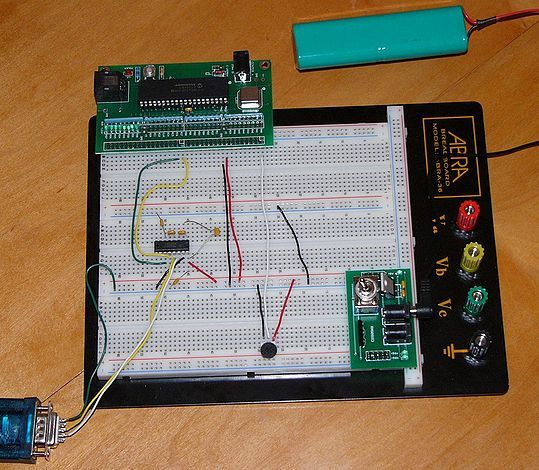
A female DB9 connector was wired to our level shifter to convert the voltages, with the level shifter connected to our PIC. The female DB9 connector is used so no wires need to be directly soldered to the serial cable. Refer to the Circuit section for details on this connection.

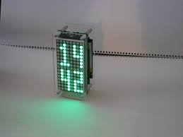
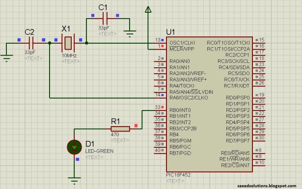
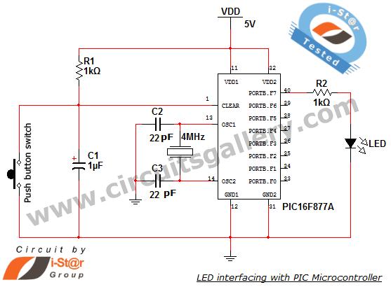
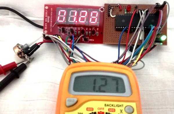
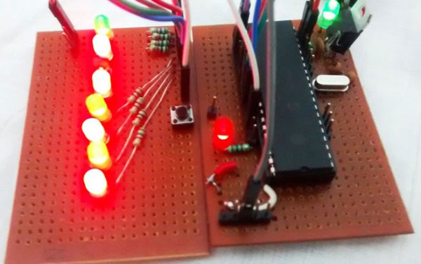
The PIC was programmed with our C code as shown below. Our program was designed to read a potentiometer through the PIC’s ADC (Analog to Digital Converter) port and transmit the digitized readings over the serial cable to the PC (upon request). In Matlab, if a users sends data to the PIC by entering a character, the PIC responds with the current potentiometer reading and the last received byte from the PC. The PIC is also programmed to display the character received from the PC on its LED array (D register) as a 8-bit ASCII number. The programs can easily be modified to create any custom protocol, but are designed to show simple 2-way communication between Matlab and the PIC.
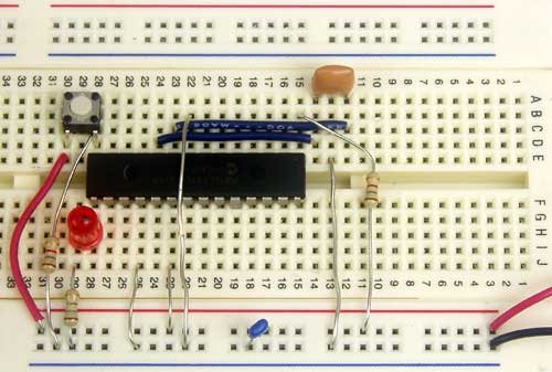
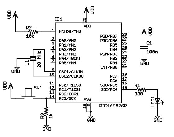
Serial communication with Matlab

Circuit

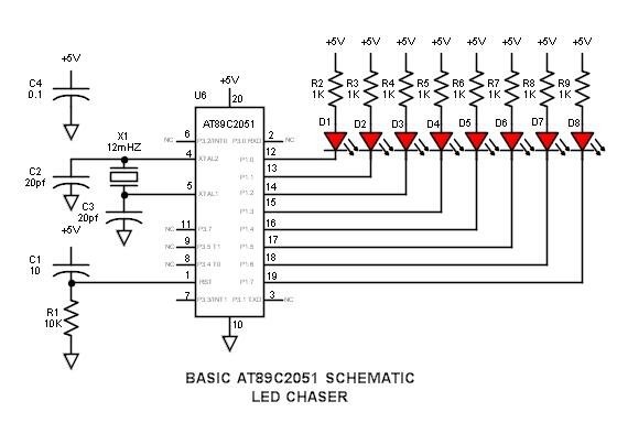
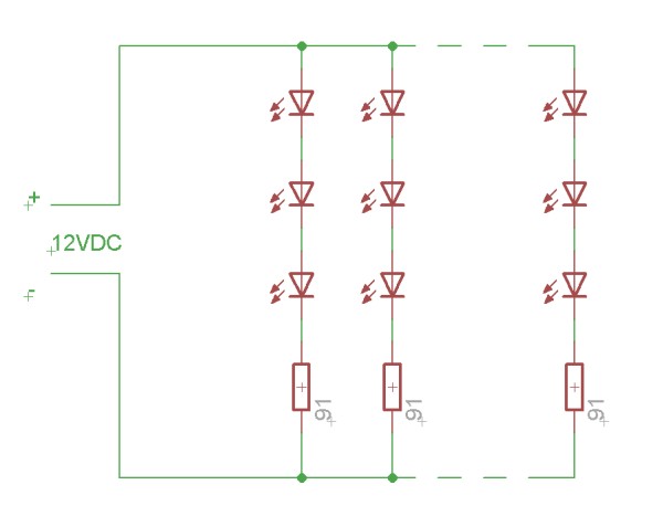
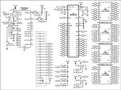
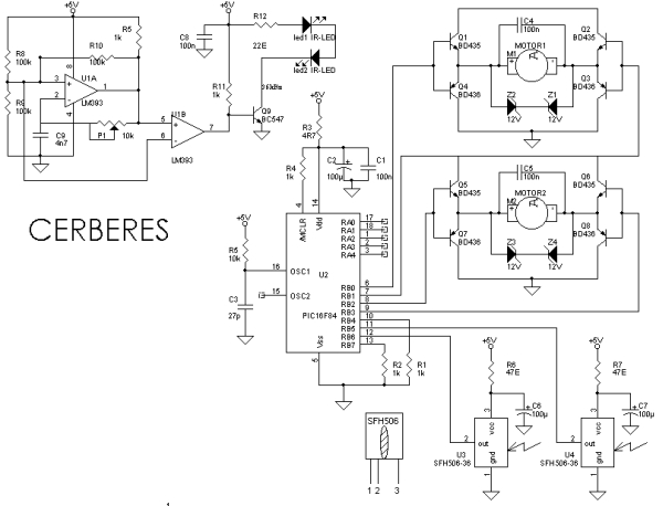
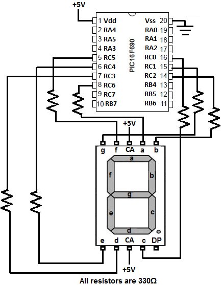
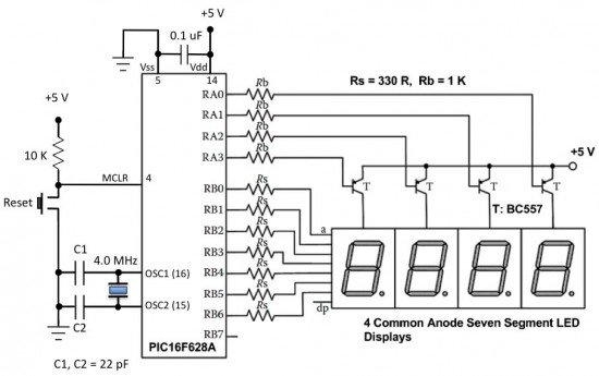
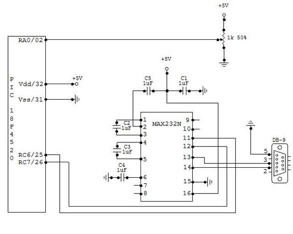
The wiring diagram for serial communication is shown below. There are three basic components in this setup. The potentiometer serves as an analog input to the PIC, which is converted to a digital signal through the PIC’s analog to digital converter pin. The MAX232N level converter provides bidirectional voltage shifting for digital communication between the PIC and PC (read more about this chip and level conversion on the RS232 wiki here). Finally, the female DB-9 connector allows the circuit to connect to the PC’s serial port.


For more detail: Serial communication with Matlab

Current Project / Post can also be found using:

  • pic18 led project

The post Serial communication with Matlab pic-microcontroller appeared first on PIC Microcontroller.


Low cost LCD module interface with optional LED backlight using PIC18F452

$
0
0

Here are the technical specifications:

  • LCD resolution: 128 x 64 pixels
  • LCD manufacturer: DisplayTech.
  • LCD model 1: 64128COG-FA-BC (no backlight)
  • LCD model 2: 64128G-FC-BW-3 (white LED backlight)
  • On-glass lcd controller KS0713, with 30 pins connector.
  • Very low power operation (less than 1mA @3V)
  • Fast serial interface (only 8 wires needed)
  • Molex miniature connector.
  • LCD: dimensions: 56 x 41 mm
  • PCB interface: Dimensions: 44 x 18 mm

LCD module


These two LCD modules can be bought in our online shop. You’ll need the interface described below and a PIC microcontroller to get these LCD modules running.

PIC example Source code (CCS C) , pcb layout and schematics (Eagle) available.  Last update: March 24, 2007.

PIC software example: routines

ccs routine example explanation
LCD initialization dt_lcd_init(); init parameters needed after power on
Clear screen dt_lcd_clear_screen(); resets all pixels, needed after power on
Cursor position set dt_lcd_gotoxy(0,5); goto cursur location x= 0..127 PIXEL COLUMNS // y= 0..7 CHAR. ROWS
Write text to LCD printf(dt_lcd_printchar,” DisplayTech LCD”); show simple unformatted text


Downloads: right-click & save as

Interface: Eagle PCB layout: 042 – 004.brd  – March 24, 2007.

 Interface: Eagle Schematics: 042 – 004.sch  – March 24, 2007.


 PIC CCS example: source code: 042_v01.zip for 18f452 @ 20MhZ – March 24, 2007.

 PIC CCS example:Hex file: 042_v01.hex for 18f452 @ 20MhZ – March 24, 2007.


For more detail: Low cost LCD module interface with optional LED backlight using PIC18F452


The post Low cost LCD module interface with optional LED backlight using PIC18F452 appeared first on PIC Microcontroller.

8051 Microcontroller Overview & Hardware – Tutorial #1

$
0
0

The intel 8051 series 8bit microcontroller, originally introduced in 1980, remains popular and has had perhaps the longest product life of all such devices. It has become the industry standard for real-time and Boolean control applications.

While some (who should know better) have said that the 8051 is dead, it continues to be a viable choice for both design upgrades and new applications as faster, more advanced versions appear. Most engineering students study this device in order to round out their education. It is generally programmed in assembly code rather than compiled from high level languages. As a result, the speed is optimized and it can often outperform modern devices that are programmed only in high level languages.

Only the also very popular Microchip PIC microcontrollers can touch the 8051 series features and performance etc. –these were introduced some 13years later, but are essentially limited to one vendor and have not caught on as an industry standard.

This is the first of a series of tutorials on these devices. While understanding the basics, I realize the limitations of my knowledge –while I can write code, make things work and pride myself on routine optimization, I freely admit that I am no expert. As a result, there will be some shortcomings in my presentation –it will be from my (perhaps myopic) point of view.8051 Microcontroller Overview & Hardware – Tutorial #1

Hardware schematic of LED Chaser

Manufacturers (not an exhaustive list –also some have already discontinued this series –perhaps too many players to corner sufficient market share)
The following vendors have either licensed or cloned the intel 8051 microcode:

AMD
Philips /NXP
Atmel 89x
Dallas-Maxim
Infineon C500
SiLabs
Cypress Semiconductor
Analog Devices
Texas Instruments
Matra /Harris
Oki
Siemens
SSI
Zilog

Initial 8051 versions

“8051” is simply the generic name given to the entire series because it was the first single chip microcontroller solution of the series. Following are six basic intel versions with which the reader should be familiar –other vendors generally construct part numbers from their own prefix and the last two digits of the these intel versions. The physical package is subsequently denoted by the suffix. Beyond this there are numerous differences, so it is necessary to study the specific datasheets.

  • 8031 128 bytes RAM, external code memory (3 chip solution –CPU, address latch, external ROM)
  • 8032 256 bytes RAM, external code memory
  • 8051 128 bytes RAM, 4K Internal mask ROM for code memory (single chip solution)
  • 8052 256 bytes RAM, 8K Internal mask ROM for code memory
  • 8751 128 bytes RAM, 4K UV erasable EPROM (quartz window) (single chip, reprogrammable)
  • 8752 256 bytes RAM, 8K UV erasable EPROM (quartz window)

The initial devices were power hungry NMOS technology –later, more efficient CMOS devices were introduced –some have various power shutdown modes to further conserve power, but in no way can they match modern “flea power” devices that are designed for long-life battery applications.

Types of memory –FYI

  • RAM Static memory for variables and the stack –variables and return address are stacked during interrupts and sub-routines etc.
  • ROM or PROM Read only (external program code memory)
  • Mask PROM Internal code memory that is masked upon manufacture and cannot be altered
  • Flash or EEPROM Electrically Erasable internal, reprogrammable code memory)
  • EPROM Read only (internal or external code memory) UV erasable via quartz window –requires programmer in order to generate the high voltage (12V) required for programming
  • OTP One time programmable (internal code memory) EPROM without quartz window

Note that the larger microcontroller devices (e.g. 40pin or larger) can access either internal or external code memory via an external data bus –the smaller devices (e.g. 20pin) access only internal code memory and cannot manage a tri-state data bus.

Atmel –best for experimenters

Of the many vendors who offer these devices, Atmel shines brightest. While other vendors have added features, flash program memory, increased the clock rate and reduced the number of clock cycles per instruction, Atmel has both doubled the speed and blown the bottom out of the price with many devices selling for approximately $1 each. Very popular is the bare bones Atmel 89C2051 in a DIP-20 package. It must be programmed in a programmer. Also very popular is the AT89S52 in either a DIP-40 or PLCC-44 package. It may be programmed in a programmer, but also has provision for in-circuit programming via the ISP serial programming interface feature that uses a simple 10pin connector –no, it cannot bootload like the AVR devices. Both devices are very inexpensive and great for the experimenter –software and programmers will also be chosen for minimum cost. Future tutorials will focus on these two Atmel devices.8051 Microcontroller Overview & Hardware – Tutorial #1 schematic

Datasheets
AT89C2051 http://www.atmel.com/images/doc0368.pdf
AT89S52 datasheet

Microcontroller Photos

Challenge

Someone, pick up the gauntlet of writing a tutorial on the PIC microcontroller.

For the future (partial list)

  • LED Chaser (basic AT89C2051 schematic driving 8LEDs)
  • AT89 Features
  • Assembly code
  • Programming tools
  • ASM51 assembler software

Undocumented words and idioms –for our ESL friends

  • flea power –extremely low power for long battery life –literally, the power of the tiny fea
  • bare bones –most simple version –literally the bones of a skeleton


For more detail: 8051 Microcontroller Overview & Hardware – Tutorial #1

Current Project / Post can also be found using:

  • establishing a serial connection between to PIC microcontrollers

The post 8051 Microcontroller Overview & Hardware – Tutorial #1 appeared first on PIC Microcontroller.

LED UV exposure box

$
0
0

Introduction

I have been using the toner transfer method for about 9 years with great results. Occasionally I would need a board with finer traces and I would use UV method. My exposure setup allowed only a single sided board to be made and it was composed of a 30cm UV tube, some holders, a table, board and film. Exposure time was rather long as the tube was far away from the board.

A few months ago I was looking for some LEDs at one of my suppliers and found that the also had UV LEDs. My mind went directly to upgrading my not so great setup, so I began looking on the internet for info. It turns out some other people have done it, and this instructable confirmed it was really possible. A LED UV box has a clear advantage over a tube one: it can be made in any size, depending on the needs.

I bought 25 LEDs and began to experiment. This way I was able to find a compromise between LED density (spacing), distance between LEDs and board and cost. I wanted something compact, I don’t make large PCBs and those 30cm tubes were not right for this job.

LED UV exposure box

Note: Don’t look directly into the UV LEDs. It harms your eyes.

The LEDs

The LEDs are OSSV53E1A from OptoSupply and they have an 140° angle. This means that the first plane with uniform density can be obtained at a shorter distance from the LED, for a given spacing between LEDs which means smaller height for the board. Their peak wavelength is 405nm, which is higher than recommended by the boards’ manufacturer. Results showed they emit sufficient UV light in the responsive spectrum of the photo resist to allow for a perfect exposure.

I wanted to use a common voltage so 3 LEDs in series with a 91Ω resistor are connected to 12V to ensure a 20mA current.

Schematic LED UV exposure box

The final setup will contain a LM317 for stabilizing as I don’t plan on using my variable regulated supply all the time. There is another reason for this, due to the non linear nature of the LEDs, varying 12V with +/-5% creates much larger current variations which influences the required time. Putting a regulator on the box simply allows more flexibility in choosing the power supply. 

On the bottom board I have added red LEDs. These LEDs help me align the top and bottom films. I have used low brightness, cheap, matte LEDs as I have to look into them when aligning the films. Connection is similar, 3 LEDs in series with a 220Ω resistor, except for the last row which contains 2 LEDs and a 330Ω resistor. These are not really necessary, aligning the films can be done in a dim ambient light.

For safety reasons and extra functionality I added a switch to turn off the UV light when the box opens, turn on the red light and stop the timer. This makes the box more high tech and gives it a professional behavior.

For more detail: LED UV exposure box

The post LED UV exposure box appeared first on PIC Microcontroller.

Using the MAX6955 LED Display Driver with a PIC Microcontroller to Scroll Messages

$
0
0

Abstract: A circuit and program listing for using the MAX6955 LED display driver with a PIC microcontroller and 14-segment displays.

The MAX6955 is an LED display driver with an I2C™-compatible, serial interface capable of supporting Fast Mode speeds up to 400kHz. It is capable of driving sixteen 7-segment, eight 14-segment, eight 16-segment or 128 separate LEDs. This application note describes a 14-segment application circuit and an example program that continuously scrolls the message:Using the MAX6955 LED Display Driver with a PIC Microcontroller to Scroll Messages

“THE QUICK BROWN FOX JUMPS OVER THE LAZY DOG”.

The program, shown in Listing 1, can be modified to scroll alphanumeric messages with a length of 8 to 126 characters. The application circuit shown in Figure 1 consists of the MAX6955, the PIC18F442 and four super bright red 14-segment dual character displays from Lumex (Part number LDD-F5406RI).

Figure 1. MAX6955 application schematic.

The example assembly program continuously scrolls the alphanumeric characters located in the lookup table of the program. The alphanumeric message length is adjustable from 8 to 126 characters long including all blank spaces (0x20). It is recommended to add 7 blank spaces at the beginning and end of the message to obtain the best scrolling effect. In order to customize the message, first modify the hexadecimal representation of the character to scroll in the lookup table of the program. Then modify the CharCount variable value to the number of alphanumeric characters in the selected message including all blank spaces. The program calculates the correct shift count using the equation:

CharCount – 7 = ShiftCountPlusOne
ShiftCount = ShiftCountPlusOne – 1

For example, “THE QUICK BROWN FOX JUMPS OVER THE LAZY DOG” contains 43 characters. Adding 7 blank spaces before and after the message increases the character count to 57. Using the equation above shows that a message with a character count of 57 would be shifted a total of 49 segments from right to left.Using the MAX6955 LED Display Driver with a PIC Microcontroller to Scroll Messages schematic

The example program also contains function calls to interface the MAX6955 to the PIC using the internal MSSP I2C port. Since other microcontrollers have similar on-chip peripherals, the example I2C communication routines provided were purposely broken down into single I2C function calls so that the code can be quickly implemented with other microcontrollers. Table 1 shows the single I2C compatible function calls used in the example assembly program.


For more detail: Using the MAX6955 LED Display Driver with a PIC Microcontroller to Scroll Messages

The post Using the MAX6955 LED Display Driver with a PIC Microcontroller to Scroll Messages appeared first on PIC Microcontroller.

Homemade temperature LED display for PC using PIC16F876

$
0
0

Since I started my watercooling prejoect, I have been verry interested in how well it perform,
the only way is to measure all temperatures before and after,
The motherboard temperature sensors is useless unacurate, so I’m using LM50B

temperature LED display
By using this LM50B sensor I get 1 C of real accuracy
I use a PIC16F876 to drive a four two digits LED displays, the PIC16 has 4 analog inputs with 10 bits resolution,
now I can display 4 temperatures at the same time to monitor performance 🙂
I monitor CPU, Chipset, GFX card, Harddisks.

Here is the schematic good old handdrawn original..
Here is the schematic Re-Drawn Maybe you like this better 🙂 OK, comments for the circuit:
You can use any number of LED displays: 2, 4, 6, or all 8, depending on how many temperatures you want to display,
LED display type must me common cathode, FET can be any N-FET type you have, I have used IRF530 I had on stock,
NPN transistors can also be used if you dont have fets, then remember to mount a 1k resistor on each base inpus.
Each sensor input connector is protected using a 1k resistor, so you can connect sensors with power on,
nothing will burn if you connect it wrong.
Only calibration requred is the refference voltage, it need to be exactly 2.5600 volt, I have used a super stable regulator,
but an LM317 can also be used to make 2.56 volt with if that is what you have. DOWNLOAD The HEX file for the PIC16F876.
The 5 volt supply is taken from a free harddrive power connector, no need to regulate it, 4.8 to 5.2 will work fine.
This complete circuit with 8 all digits consume about 100mA. Good Luck.


For more detail: Homemade temperature LED display for PC using PIC16F876

Current Project / Post can also be found using:

  • temperature measurement using pic microcontroller

The post Homemade temperature LED display for PC using PIC16F876 appeared first on PIC Microcontroller.

An LDmicro Tutorial

$
0
0

In this tutorial, I will show you how to write a very simple program. I am assuming that you have written ladder logic before, and that you have some basic familiarity with microcontrollers, but that you have never used LDmicro. If you don’t know very much about ladder logic or PLCs, then the plcs.net tutorial might be helpful to you.

Our device will have one pushbutton, and one LED. At startup, the LED will be off. When you press the pushbutton once, the LED will turn steady on. The second time you press the pushbutton, the LED will start blinking. The third time that you press the button, the LED will turn off again. On subsequent presses, the cycle will repeat.

Microcontroller Selection and Schematic

We will be using a PIC16F876, which is easily available from Digikey or other online distributors. It comes in a number of different packages; I chose a DIP.

Note that as of Nov 2009, the PIC16F876 is no longer recommended for new design. This means that it will probably get discontinued at some point in the next few years. You may prefer to instead use a PIC16F886, which is pin-compatible. If you do, then make sure to specify the correct part when you compile, since the ‘F886 is not code-compatible.An LDmicro Tutorial

This is our schematic:

The microcontroller (IC1) is part number PIC16F876-20I/SP-ND at Digikey. Almost any three-terminal resonator (U1) will do; you might try a 535-9356-ND or an X909-ND.

The only thing that might confuse you is that the pushbutton goes to Vdd, and there is a pull-down. You might be more used to seeing a pushbutton to ground with a pull-up. For TTL, this mattered. For modern CMOS it does not, and I find this `active HIGH’ arrangement less confusing than the traditional `active LOW’ circuit.

Also, I chose to use a ceramic resonator with internal capacitors, U1, instead of a crystal and two ~20 pF caps. A crystal would work just as well and it would be more accurate, but it would be a little bit more expensive, and you would need more parts.

You could build this circuit in many different ways. I built it on a solderless breadboard, and it ended up looking like this:

(The resistor values pictured are not quite the same as the schematic; none of them are critical.)
Ladder Diagram for the Program

First, we are going to need an oscillator to generate the `blinking’ signal for the LED. There is a standard way to do this in ladder logic:

This will flash at 1/((250+250) ms), or 2 Hz, or twice per second. The duty cycle will be 50%—250 ms on, then 250 ms off. This circuit can make any kind of oscillator, with whatever period or duty cycle you require, so it is a good one to remember.

Also notice that we have chosen to use an internal relay (`Rfoo’) instead of one attached to an I/O pin (`Yfoo’ or `Xfoo’). This makes sense, because there is no particular reason to bring that signal out to a pin. LDmicro will automatically assign memory for the internal relay.

Our program will have three states: off, steady on, and blinking. The program should change its state on each rising edge of the signal from the pushbutton. This is a good application for a circular counter. We will say that `state 0′ is `off,’ `state 1′ is `steady on,’ and `state 2′ is `blinking.’ The counter counts 0, 1, 2, 0, 1, 2, …, so if we just let the rung-in condition of the counter be the pushbutton input, then everything will work like we want:

Now the only thing left is to use the program state to set the state of the LED. We can do it like this:

It should be easy to convince yourself that this does what we want. If the program is in state 1, then the `Cstate == 1′ instruction energizes `Yled’, as desired. In state 2, the `Cstate == 2′ instruction energizes `Yled’, but only when `Rosc’ is also true. Since `Rosc’ is oscillating, that means that the LED will blink, as desired. Finally, in state 0, neither of the equals instructions will be true, so there is no way that `Yled’ could ever turn on.An LDmicro Tutorial schematic

Entering the Ladder Diagram

Now that we have our circuit, we can draw it in LDmicro. When you start LDmicro, you will see a single empty rung:

We want to enter the first rung from the listing above. We will start with the coil, so choose Instruction -> Insert Coil. This will create a coil named `Ynew.’ This is what we want, except that the name is wrong, and it should be negated. Double-click the coil; this will bring up a dialog where we can fill that in:

Now we can insert the rest of that rung in the same way. Click on the left edge of the coil, so that the cursor is vertical, and to the left of the coil. Now choose Instruction -> Insert TON (Delayed Turn On). Once again double-click the timer to rename it and set the period. Add the TOF timer and the contacts in the same way.

Now we want to enter the second rung, so choose Edit -> Insert Rung After. Then click on the second rung to move the cursor there:


For more detatl: An LDmicro Tutorial

The post An LDmicro Tutorial appeared first on PIC Microcontroller.

100MHz frequency counter with PIC16F628A – LED Display

$
0
0

Couple of weeks ago I purchased from eBay one of these amazingly cheap an useful modules with MAX7219 LED driver and 8 digit LED display. It is ideal for frequency counter project. The problem was the absence of library for PIC microcontrolers. Luckily, I found a great library for Arduino and I reworked it to be compatible with PIC. The schematic of the frequency counter is actually almost the same as the previous . It uses PIC16F628A microcontroller with external 32.768kHz watch crystal attached to Timer1 to generate 1 second time base. Measured signal is fed to pin3 (RA4) which is counted by Timer0.

100MHz frequency counter with PIC16F628A – LED Display

The program make short (0.125s) test of the input signal to determine the prescaler value. Next is the actual counting with the proper prescaler value and then the result is send to the display.

This is fast breadboard proof-of-concept project, and I don’t intend to make a finished product, for now at least. Of course there must be some sort of preamplifier/protection in front of the frequency counter in order to be usable.

In the pictures below is shown the breadboard and five different quartz crystals generating different frequencies. The differences between the value on the display and the value on the oscilloscope are negligible. I tested the schematic also with frequencies above 90 MHz and even above 100Mhz and the results was accurate, but of course most significant digit was lost in case of 100+ MHz.

Schematic

Schematic 100MHz frequency counter with PIC16F628A – LED Display

For more detail: 100MHz frequency counter with PIC16F628A – LED Display

The post 100MHz frequency counter with PIC16F628A – LED Display appeared first on PIC Microcontroller.


12 DIGIT RUNNING SIGN using PIC16F628

$
0
0

It’s 1970 and a 12 digit LED Display for pocket calculators has just been released.
Nation Semiconductors are in the forefront of designing miniature displays for calculators and have a range from 2-digit to 16-digit displays.
The actual 7-segment displays are so small it takes a bubble magnifier in front of the LEDs to see the digits. We have used one of these in this project.

Fast forward to 2011. These displays are now obsolete and we can find them in surplus stores for a few dollars.
In this project we use one to produce a LED display. It has two features. The characters can be static or “running” and the display can be seen at night.

12 DIGIT RUNNING SIGN

HOW THE CIRCUIT WORKS
The circuit consists of a number of “Building Blocks.”
The main blocks are the LED display, the micro, the 4017 IC and the 5-buttons.

The display is scanned (multiplexed) but not in the normal way.
Normally the segments are accessed and the common cathode for the first display is turned on to produce a run-of-12 and each display would get 8% of the total time.
In other words the digits are illuminated from left-to-right and this is done quickly so that they all appear to be lit at the same time.
But we can improve on this by a factor of 50% by connecting all segment A’s together, all B segments together etc and take all the cathodes to 0v rail via separate lines. In this way we can access the segments via a run-of-eight and provide 12% illumination for each segment. This will result in a brighter display.
This is how the display is configured internally and how the display is intended to be accessed.
In this method of driving the display, only one segment of each digit is turned on at any time and this means the “common” only requires about 25mA “sinking capability.” This requirement can be handled via the micro, while the emitter-follower from the 4017 drives all 12 segments (such as segment “A”) at the same time.
We supply 25mA (actually sink 25mA) via the micro but when this is divided by a run-of-eight, the average current is only 3mA to each segment. However this is sufficient to produce a bright display.
The 4017 must be synchronised with the data being delivered to the display from the micro, otherwise the wrong segments will be illuminated and the correct image will not appear.
Synchronisation is done by monitoring “output 8” – the 9th output of the 4017 IC and when it is high, we can clock the 4017 to the first output, ready for the start of the scanning routine.
The 4017 is a “shifting chip” in which one output of the 10 is HIGH at a time. We use this to access the 8 segments and the 9th output is taken to the micro to produce co-ordination between the two chips.
The 5 keys on a single input/output line is polled for activity by calling the Sw sub-routine and if a button is pressed, the program goes to the sub-routine associated with the button.
To find which key has been pressed, a 100n capacitor is charged via output RA6 of the micro. The line is then turned into an input and polled to see if the capacitor discharges. If one of the buttons is pressed it will get discharged before a 20mS time-interval and the routine knows a button is pressed.
The capacitor is now charged again and the line is turned into an input and the time taken for the capacitor to discharge, via the button being pressed, is detected.
The resistor values have been chosen to produce different timings and the sub-routine detects the correct button.
The micro has two 8-bit ports. 4 lines from port A and 8 lines from port B have been used to take the common cathodes of each digit to 0v.
The micro will allow 25mA to flow though the common cathode of each digit and this is sufficient to produce a bright display via the multiplexing routine we have used.
All the rest of the features of this project are in the program.
The numbers and letters for the display are contained in a table and only a few of the letters are missing as they cannot be reproduced.

HOW THE PROGRAM WORKS
This program consists of sub-routines and these are placed in alphabetical order so they can be easily located when working on the program.
All the code was created and tested by creating one sub-routine at a time and if a problem develops, you can add a halt instruction to the program (goto $) and see how a particular part of the code operates.
The micro starts at location 000 and carries out the Start-Up routine.
It then goes to Main where it finds a number of instructions to call sub-routines. One of the sub-routines is the switch or button routine where it checks to see if a button has been pressed.
The most difficult code to generate was the timing for the 5 buttons.
We had to work out the timing (delay value) and resistor value for each button. We created a sub-routine where button 1 turned on segment A, button 2 turned on segment B etc. We then added a 100k pot and a separate button. By turning the pot, a particular segment was illuminated. You will find this sub-routine as “Sw” in the final program. We then found the resistance where one segment turned off and the next segment turned on.  These became the limits for each segment (by measuring the resistance of the pot) and we chose a resistor mid-way between the two values.
A button can be pressed at any time and it is detected by charging a 100n capacitor while the button is pressed and measuring the time for the cap to discharge via a resistor connected to the button.
Each button has a different resistance and a loop of 2mS is executed. When a LOW is detected, a count-value is created and this corresponds to a button.

For more detail: 12 DIGIT RUNNING SIGN using PIC16F628

The post 12 DIGIT RUNNING SIGN using PIC16F628 appeared first on PIC Microcontroller.

Small 3-wheel ROBOT with PIC16F84 brain & InfraRed eyes.

$
0
0

General description

erberes is a small three wheel robot that avoids obstacles which it senses with its active infrared sensors.

Each rear wheel has its own motor, the single front wheel is not powered. The robot steers “like a tank” by rotating the rear wheels in opposite direction.

The sensors are built with infrared LEDs which are running at 36kHz and two 36 kHz remote control receiver modules.
When the 36 kHz infrared light from the LEDs is reflected by an object, one of the receiver modules will be triggered, and the PIC16F84 µController will steer the ROBOT away from the objects by reversing one of the motors.

Small 3-wheel ROBOT with PIC16F84 brain & InfraRed eyes. Mechanics

Two electric toy ducks were sacrificed for this project.
The motors, axes and axe-holders from the toy ducks are glued on a piece of circuit board which acts as a base plate.
The rotation speed of the motors is reduced by the “worm-wheel” of the motor axes which drive the cogs of the wheel axes.

The circuit is built on another piece of circuit board which is identical to the base plate.
The circuit is placed on top of the base plate.
The 3.6 Volt battery pack (from a cordless phone) is also glued to the base plate.

Circuit description

The circuit behind CERBERES can be divided in 3 parts:

  1. A double motor drive to drive two small electric motors forward / reverse / full stop.
  2. Two infrared emitters and receivers to sense objects.
  3. A “brain” which is a PIC 16F84 µController which will drive the motors in reaction to the sensor readings.

The Motor Drive circuit

Both motors are driven by an identical full bridge circuit. The circuit of Motor1 will be used to explain the functionality.
Motor1 is driven by a full bridge built with transistors Q1, Q2, Q3 and Q4.
This full bridge is able to drive the DC motor forward backward and full stop by driving the base
connections of  Q1/Q4 and Q2/Q3 as in the table below:

base Q1/Q4 base Q2/Q3 Motor1 action
0 Volt 0 Volt STOP
0 Volt 5 Volt REVERSE
5 Volt 0 Volt FORWARD
5 Volt 5 Volt STOP

The transistors are switched as “emitter followers” which results in a voltage loss of 2 x 0.6 Volts. In this case the
voltage drop was very useful because the the motors from the toy ducks were much too fast at
Cerberes’ battery voltage of 3.6Volts.

The base drive of the transistors limits the output current to about 1-2 Amps typical at 3.6Volts:
The maximum current from the PIC µController is 20mA at 5Volt , the typical Hfe of the BD43 /436 is 130;
this results in a  typical maximum current of 20mA x 130 = 2.6 Amps at 5 Volt supply.
When the low operating voltage of 3.6 V is taken into account the max PIC current is even lower: about 1-2 Ampere.

When using other transistors, take into account that a Hfe of 100 or more is required.
The motors from the toy ducks use about 1 Ampere at 2.4 Volts The battery pack has a capacity of about 300mAh
resulting in a typical operating time of about 9 minutes!

Small 3-wheel ROBOT with PIC16F84 brain & InfraRed eyes SchematicThe Infrared Sensors

In the schematic above, LM393 comparator U1A is used as a 36 kHz oscillator. The frequency is adjusted to exactly 36 kHz
with (multiturn) potentiometer P1.
U1B is a buffer which picks up he oscillator signal without influencung the frequency setting.
The signal is passed on to Q9 which switches two Infrared Leds (e.g. from a remote control) at 36 kHz.
The LM393 is used because it can operate at very low voltages down to 2 Volt , a standard opamp can not be used here!

U3 & U4 are standard SFH506 36kHz infrared receivers which are normally used yo pick up IR signals from
an IR remote control.


For more detail: Small 3-wheel ROBOT with PIC16F84 brain & InfraRed eyes. 

The post Small 3-wheel ROBOT with PIC16F84 brain & InfraRed eyes. appeared first on PIC Microcontroller.

Quick & Easy RGB-LED Tester using PIC16F627 microcontroller

$
0
0

Quick & Easy RGB-LED Tester

Have you ever built a project with a lot of LEDs, and found out that one of the LEDs was defective? Although it’s somewhat rare, there are some defective LEDs when you go through hundreds of them. I found that RGB-LED have high defect rate, most likely due to the fact that each of them has three LEDs (R,G,B) in them.

I have had a few situations where one of the RGB LEDs was not working fully, and having to desolder to remove it. Here because RGB LEDs have four leads instead of two, desoldering is difficult.

So here’s the quick & easy RGB-LED test that I build on a breadboard. You can build this in less than 15 minutes and save a big hassle later!

LED Tester

Putting it together

Here’s the part list:

1x Breadboard (small one is fine)
1x PIC16F627, 628A or 648A
1x 0.1 uF capacitor
1x 20 k ohm resistor
3x 220 ohm resistors
3x 470 ohm resistors
3x 120 ohm resistors
some jumper wires
1x 5V regulated power supply or 4x NiMH batteries in a holder

You’ll also need a programmer capable of programming PIC microcontrollers, such as MPLAB ICD or PICKit.

As you can see, the circuit & construction is very simple. Once you have the parts, just put them on a breadboard in 5 minutes! Use the picture as the reference.

Then fire up your programmer and you are ready to go.

The post Quick & Easy RGB-LED Tester using PIC16F627 microcontroller appeared first on PIC Microcontroller.

PIC18F452 LED Blinking Code and Proteus Simulation

$
0
0

This post provides the LED blinking code (compiled in MPLAB + HI-TECH C) for PIC18F452. Complete project code and the proteus simulation can be downloaded from the Downloads section at the bottom of this post. The following diagram shows the required circuit.

PIC18F452 LED Blinking

In this project a crystal of 10MHz is used with PIC18F452. This crystal frequency is fed into PLL of PIC18F452, which boosts it to 40MHz. As we know that any PIC micro controller has an architecture which executes an instruction in 4 CPU cycles, hence this 10Mhz crystal + PLL makes this PIC run at 10MIPS (Million of instructions per second). The code for this project is shown below.

PIC18F452 LED Blinking schematic

Downloads

The code was compiled in MPLAB v8.76 with HI-TECH C and simulation was made in Proteus v7.7.
To download code and proteus simulation click here.


For more detail: PIC18F452 LED Blinking Code and Proteus Simulation

Current Project / Post can also be found using:

  • pic12f675 ic led contorolar

The post PIC18F452 LED Blinking Code and Proteus Simulation appeared first on PIC Microcontroller.

PIC16F690 Microcontroller Circuit- How to Drive an LED Display

$
0
0

In this article, we will show how to drive a 7 segment LED Display using a PIC16F690 microcontroller.

This PIC16F690 microcontroller chip is actually a part of the PIC2 Starter Kit, so we will actually be using this starter kit to drive the LED Display.

A 7 Segment LED Display is an electronic device that contains 8 individual LEDs. Each of the LEDs can either be on or off. Depending on which LEDs are lit determines the character which is displayed. The LED display can show any number from 0 to 9. It can also show many alphabetical characters.

In this project, we will use the PIC16F690 microchip contained in the PIC2 Starter Kit to control the 7 segment LED display so that we can light up whichever segments we want to display whatever characters we want in sequence.PIC16F690 Microcontroller Circuit- How to Drive an LED Display

A 7 segment LED display is a valuable electronic device because used in conjunction with other LED displays, it can function as a numerical display, such as time for a clock, a display for a game scoreboard, or any such other numerical display. So it is a very valuable electronic device to know how to operate.

Using a microcontroller to drive an LED display is much more easy and efficient than not. If we did not have a microcontroller to drive an LED, in order to display different numerical values, we would need someone to manually change which turn on or off different LEDs in the LED display. This would be much less efficient than using a microcontroller. When a microcontroller, in this case a PIC16F690 microcontroller, is connected to an LED display, all we need to do to change the software to display different characters. Changing the hardware, which LEDs are lit, is much more complex and time-consuming and, thus, is simply not efficient.

We will now show how to connect and program the PIC16F690 microcontroller to drive an LED display. Specifically, for this circuit, we will drive one LED display, for simplicity, to count from 0 to 0 and then reset back to 0.

Again, a 7 segment LED sipaly is made up of 8 individual LEDs. Thus, the microcontroller needs enough I/O pins to connect to each of the 8 terminals of the 7 segment LED display. It’s the job of the software to light them in the proper order to create the numbers 0 to 9.

For this project, we will use a common anode LED display, which is a display all the anode leads are common and the cathode leads are not. To understand the difference between common anode and common cathode displays, see What is a 7 Segment LED Display.

Schematic

The schematic of the PIC16F590 microcontroller chip connected to the LED display is shown below:

The PIC16F690 can drive an LED directly from an I/O pin because it can output up to 25ma of current. The whole port can supply 200ma in total maximum. We connect 330Ω resistors to the outputs to limit current so that the LEDs don’t receive too much current and burn out. They are safety current-limiting resistors.

The only connections we need is 5 volts of power to the Vdd pin and to have the Vss pin connected to ground. However, if you plug in the PICkit 2 programmer, you can get power from it and, thus, would not have to make power connections. This reduces more connections.

The PIC16F690 has an internal oscillator that we will run at the default speed of 4MHz. The MCLR master clear reset pin will be set to internal mode so we don’t need any external reset circuitry. Those are both setup in the configuration register of the PIC16F690. We control that configuration in the software.PIC16F690 Microcontroller Circuit- How to Drive an LED Display schematic

Being that the LED display is common anode, all the anodes are tied together (are common). The cathodes are separate and tie down to ground. For an LED to have a complete circuit and turn on, the LED needs to connect to ground. This will happen if its cathode terminal is connected to ground. Thus, if an LED segment is connected to ground it is on. This is why an LED turns on if it is low. If the LED is connected only to the anode’s positive voltage, it is HIGH and off. This will be important when coding, because a 0 will represent an ON LED and a 1 will represent an OFF LED.

Code to Drive LED Display

The code need to drive an LED display is written for the HI-TECH PICC PRO compiler. This can be done in lite mode.

This will sequence 0 to 9 at a 1/2 second rate. It is a common anode display driven by PortC.


For more detail: PIC16F690 Microcontroller Circuit- How to Drive an LED Display

The post PIC16F690 Microcontroller Circuit- How to Drive an LED Display appeared first on PIC Microcontroller.

LED Interfacing with PIC Microcontroller: Embedded C program with circuit using pic microcontoller

$
0
0

How to interface LED with Microchip’s PIC microcontroller? How to connect LEDs to a PIC microcontroller? LED interfacing is the stepping stone for microcontroller development. This is a simple embedded program for PIC 16F877A to interface LEDs, suitable for beginners who wish to study basics of embedded microcontroller programming. The program is developed through Micro C compiler, one of the best solutions for embedded programming in PIC family. It is compatible for Windows XP and Windows 7 platforms and comes with internal burning tools. This PIC circuit is a beginner circuit, do this PIC project to explore the world of microcontrollers.

LED Interfacing with PIC Microcontroller Embedded C program with circuit using pic microcontoller

Algorithm for implementing this PIC project

  1. Specify the output port [here PORT B is used to connect LEDs, So TRISB=0×00; comment is used for specifying the output port]
  2. Start infinite loop [while(1){} is used here]
  3. Pass 0×00 value to the output port [PORTB=0×00;]
  4. Provide a delay. The inbuilt delay function, that is delay_ms(); gives some delay. You can change the duration of LED blinking by giving any value to the calling field of this function. For example delay_ms(1000); will give 1 second delay.
  5. Pass 0xFF value to the output port [PORTB=0xFF;]
  6. Provide a delay [delay_ms(1000);]
  7. Repeat the loop.

LED interfacing embedded C Program for PIC microcontroller

void main()
{
TRISB=0×00;
while(1)
{
PORTB=0×00;
delay_ms(1000);
PORTB=0xFF;
delay_ms(1000);
}
}
The while loop will execute infinitely. So all 8 LEDs connected to PORT B starts blinking with 1 sec delay. This program is tested and verified under i-St@r laboratory.

Read further: Loops in C programming

LED Interfacing with PIC Microcontroller Embedded C program with circuit using pic microcontoller

Circuit diagram of PIC project

What is Next?

Now we want to build a .HEX file for this program and then burn it in to our PIC microcontroller..! Dig further


For more detail: LED Interfacing with PIC Microcontroller: Embedded C program with circuit

The post LED Interfacing with PIC Microcontroller: Embedded C program with circuit using pic microcontoller appeared first on PIC Microcontroller.

Spooky Led Lamp using PIC12F675 microcontroller

$
0
0

Spooky Led Lamp

This is a hollowed out light bulb filled with fluorescent liquid and two UV leds plus one red led immersed in the liquid. When turned on the light bulb flickers for a while then starts to pulsate randomly with the UV leds giving a spooky but rather nice look.

Spooky Led Lamp

The bulb is held to the box by two small magnets that also is used as contacts for the power to it.

I got the inspiration for the project when I stumbled upon a web site describing a similar project.
imakeprojects.com/Projects/glow-crystal/

In the last step of this instructable there are two videos of it in action

Step 1: What you need

To make this project yourself you need the following items:

    • Two UV leds
    • One red led
    • One PIC12F675 microcontroller
    • Three 120 ohm resistors
    • One diode
    • Two light bulbs, one should have clear glass
    • Two strong small rare earth magnets
    • Two small screws
    • A small piece of flat plastic
    • A box

Then you need some tools and other equipment like:

  • Some tiny wires
  • Soldering iron and solder
  • Wirecutter
  • Hotglue or epoxy
  • A PIC programmer
  • Clean water
  • A highlighter pen

Step 2

Preparing the lightbulbs

The glass bulbs are incredibly strong and resilient to external force but I suggest that you hold the bulb with gloves or in a thick towel. The glass might shatter and give you a nasty cut in the hand. Some protective eyewear or at least ordinary glasses might also be a good precaution…

You need to separate the actual glass part from the metallic base of the bulb keeping both of them intact. When I tried to do that I quickly realized that it’s next to impossible to do that so you need two bulbs.

Step 3

Bulb 1 – Keep the glass

Keep the glass

From the first bulb we will keep the glass;

The blob
‘Begin by taking your wirecutter and try to snip off and pry away the soft metallic blob at the absolute bottom of the bulb.

The dark glass
When you removed it there’s a small hole in the dark glassy part in the bottom where you can insert a small metallic object (small screwdriver) and carefully break the dark glass into smaller pieces.

The metallic part
You can now start to cut away the metallic part and carefully “roll” the metal from the bulb much like when you open a tin can with sardines.

Hacking away at the glass
Now we need to remove some of the glass since we need a hole large enough to get rid of the innards of the bulb. We also need the hold large enough fit three leds in it. So start by breaking of the long narrow part that sticks out inside and then very carefully enlarge the hole so you can pull out the filament from the bulb.

Step 4

Bulb 2 – Keep the threaded metallic part

Here we only need to keep the threaded metallic part intact, so we can hack away without any caution or finesse.

Begin by removing the soft blob and the dark glassy part as in the previous step.

Then wrap the bulb in some newspaper and hit it with a hard object so the glass breaks. Remove the shards and start hacking away at the cement that the manufacturer used to bond the glass to the threaded metallic part.

It can take quite a while to get rid of all the cement from inside the metal, but it’s not too difficult to do it.

When finished with this you’ve got a hollow bulb (from the other bulb) that you can insert into the threaded part from this step. The bulb should have glass about 1 cm (1/3 inch) down into the metal when fully inserted.

Step 5

Preparing the power connector in the bulb

Take a piece of plastic that fits nicely in the bottom of the metal part of the bulb. Screw in two screws in it and connect a piece of wire to one of the screws and the diode to the other.

I did this by just drilling a two small holes in the plastic, putting the cable and one lead of the diode into the holes and then screwed in the screws. This makes a good contact without any soldering.

It is the lead on the diode without the ring that should be put into the hole. Otherwise it will not conduct when the polarity of the power is right.

Then glue the plastic to the metallic part from the lamp having the heads of the screws facing outwards.

Step 6

Preparing the power connection in the box

Drill a hole in the top of the box and make sure that the power connector of the bulb fits in there.

Take a small piece of wood and drill two holes at the same distance between them as the screws you put in the bulb power connector. The holes should be the same size as your magnets so you can squeeze the magnet together with a a poser lead into the hole.

Glue the small piece of wood inside the box and adjust it so the screws on the bulb power connector snaps in place at the magnets and the bulb is held in place.

Step 7

The leds

The leds must fit into the hole of the glass bulb so I filed the edges of the leds down just a bit and then glued them together.

I had a a small metallic gasket/ring that I put the three leds into and glued them in place there. By chance the gasket fitted almost perfectly onto of the opening of the glass bulb.

Solder the three long leads (the anodes / positive pin) of the leds together and solder a wire to it. Then solder the 120 ohm resistors to each of the short leads (cathodes / negative pin) of the leds.

Be sure to trim everything down as short and tight as possible.

Current Project / Post can also be found using:

  • led pic project

The post Spooky Led Lamp using PIC12F675 microcontroller appeared first on PIC Microcontroller.


LED Heart PWM Fading using PIC18F252

$
0
0

With my Grandma’s birthday fast approaching I wanted to put something together that was not too complicated but still sweet enough to make for a cool widget gift. Since fading LEDs never seem to go out of style and grandmas always love to see a heart, putting two and two together here was a no-brainer.
The concept for this small birthday present was to create a small heart shape with red LEDs and then to draw a heart shape underneath it on the PCB as a backdrop. Then a microcontroller was added to control the LEDs for both fade and pattern control. Controlling LEDs via PWM allows us to save precious battery life and control the exact brightness of each specific LED.

LED Heart PWM Fading

Purpose & Overview Of This Project
The goal of this project is to create a PCB with some LEDs connected to a microcontroller. The LEDs should be individually controlled by the microcontroller so much so that each LED can be set to a different brightness level individually. With this control in place 6 modes of operation should be programmed:

  • LEDs ‘around the heart’
  • A total heart fade-in-out
  • A wave-like fade bottom to top
  • A wave-like fade right to left
  • A single row fade in and out
  • A single column fade in and out.

To achieve this goal, we will use 16 5mm Red LEDs for the heart and a PIC 18F252 microcontroller for the processing. Some other components will be needed as well, so please continue on to see the parts list.

Parts
PIC 18F252
PICKit2 PIC Programmer
7805 +5v Regulator
16x Red 5mm LEDs
16x 100Ω Resistors
10kΩ Resistor
20 MHz Crystal
Toggle Switch
2x 1uF Capacitors
0.1uF Capacitors
2x 15pF Capacitors (22pF is ok)
+9v Battery Holder
4x Stand-Offs
Balsa Wood Mount
PC Board
Ferric Chloride (Etchant)
Glossy Paper
Laser Printer
Solder
Soldering Iron


Parts List Details
There are a lot of parts to this project. Too many to describe them all in detail, however below I have given some further information on the main parts that we’ll be using.

PIC 18F252
This is a small microcontroller (processor + memory). It wil be incharge of controller each LED individually, which is the main goal of this project. PICs are very versatile, in fact this PIC 18F252 has a lot more functionality built into it than just technology for fading LEDs. It’s a shame we’re not using more of the hardware on this bad boy.

PICKit2 PIC Programmer
In order to get your program (firmware) onto the PIC, you will need a programmer. The PICKit2 is a programmer/debugger and one of the most popular tools for programming PICs.

16x Red 5mm LEDs
16 LEDs will be used to create the heart shape. This isn’t very many LEDs and so the heart will likely look ‘pixelized’ but I’m okay with that, you can use more if you want to.

20 MHz Crystal
The crystal used for this project doesn’t matter so much. 4 MHz, 1 MHz or 40 MHz could have been used. 20 MHz is just the first crystal I found when rooting around my tool kit.

PC Board and Ferric Chloride (Etchant)
Since I want to make a PCB, we’ll need some raw PC Board (copper on both sides) and some ferric chloride to etch away the unwanted copper. We’ll use the toner transfer method to make the PCB.

Schematic Overview
The schematic for this project is not too terrible, it’s mostly connecting the LEDs to current limiting resistors and then to the PIC. Although it might seem that I arbitrarily chose connections for each LED, there’s reason for each LED # to connect where it is: it makes the layout process easier for us.

LED Heart PWM Fading schematic

Schematic Specifics

+5v Power Regulator and On/Off Toggle Switch
A 7805 Linear Regulator will be used to regulate the +9v battery down to +5v that the PIC needs to operate. The toggle switch connects the entire circuit to ground allowing current to flow through the circuit, thus turning it on or off.

PIC Microcontroller + 100Ω Resistors
The PIC’s general purpose outputs on PORTA, PORTB and PORTC will be used to connect to each individual LED thus giving us maximum control over each LED when programming to tell it what to do. 100Ω current limiting resistors are placed between the general purpose I/O port and the LED so that we don’t burn out the PIC or the LED by allowing too much current to flow through the microcontroller’s pin or the LED.


For more detail: LED Heart PWM Fading using PIC18F252

The post LED Heart PWM Fading using PIC18F252 appeared first on PIC Microcontroller.

Using ADC Module of PIC Microcontroller with MPLAB and XC8

$
0
0

This is our 9th tutorial of Learning PIC microcontrollers using MPLAB and XC8. Till now, we have covered many basic tutorial like getting started with MPLABX, LED blinking with PIC, Timers in PIC, interfacing LCD, interfacing 7-segment etc. If you are an absolute beginner, then please visit the complete list of PIC tutorials here and start learning.

Using ADC Module of PIC Microcontroller with MPLAB and XC8

Using ADC Module of PIC Microcontroller with MPLAB and XC8

In this tutorial, we will learn How to Use ADC with our PIC microcontroller PICF877A. Most of the Microcontroller projects will involve an ADC (Analog to Digital converter) in it, because it is one the most used ways to read data from the real world.  Almost all the sensors like temperature sensor, flux sensor, pressure sensor, current sensors, voltage sensors, gyroscopes, accelerometers, distance sensor, and almost every known sensor or transducer produces an analog voltage of 0V to 5V based on the sensors reading. A temperature sensor for instance may give out 2.1V when the temperature is 25C and go upto 4.7 when the temperature is 60C. In order to know the temperature of the real world, the MCU has to just read the output voltage of this temperature sensor and relate it to the real world temperature.  Hence ADC is an important work tool for MCU projects and lets learn how we can use it on our PIC16F877A.

Also check our previous articles on using ADC in other microcontrollers:

ADC in PIC Microcontroller PIC16F877A:

There are many types of ADC available and each one has its own speed and resolution. The most common types of ADCs are flash, successive approximation, and sigma-delta. The type of ADC used in PIC16F877A is called as the Successive approximation ADC or SAR in short. So let’s learn a bit about SAR ADC before we start using it.

Successive Approximation ADC:  The SAR ADC works with the help of a comparator and some logic conversations. This type of ADC uses a reference voltage (which is variable) and compares the input voltage with the reference voltage using a comparator and difference, which will be a digital output, is saved from the Most significant bit (MSB).  The speed of the comparison depends on the Clock frequency (Fosc) on which the PIC is operating.

Now that we know some basics on ADC, lets open our datasheet and learn how to use the ADC on our PIC16F877A MCU. The PIC we are using has 10-bit 8-channel ADC. This means the output value of our ADC will be 0-1024 (2^10) and there are 8 pins (channels) on our MCU which can read analog voltage. The value 1024 is obtained by 2^10 since our ADC is 10 bit. The eight pins which can read the analog voltage are mentioned in the datasheet. Lets look at the picture below.Schematic Using ADC Module of PIC Microcontroller with MPLAB and XC8

The analog channels AN0 to AN7 are highlighted for you. Only these pins will be able to read analog voltage. So before reading an input voltage we have to specify in our code which channel has to be used to read the input voltage.  In this tutorial we will use channel 4 with a potentiometer to read the analog voltage at this channel.

The A/D module has four registers which has to be configured to read data from the Input pins. These registers are:

• A/D Result High Register (ADRESH)

• A/D Result Low Register (ADRESL)

• A/D Control Register 0 (ADCON0)

• A/D Control Register 1 (ADCON1)

For more detail: Using ADC Module of PIC Microcontroller with MPLAB and XC8

The post Using ADC Module of PIC Microcontroller with MPLAB and XC8 appeared first on PIC Microcontroller.

LabVIEW motion controller using pic microcontroller

$
0
0
In Lab 6, we discussed about interfacing a seven segment LED display to a PIC microcontroller. The seven segments were driven individually through separate I/O pins of the microcontroller. If we do just like that then for 4 seven segment LED displays, 28 I/O pins will be required, which is quite a bit of resources and is not affordable by mid-range PIC microcontrollers.
LabVIEW motion controllerThat’s why a multiplexing technique is used for driving multiple seven segment displays. This tutorial shows how to multiplex 4 common anode type seven segment LED displays with a PIC16F628A microcontroller.

Circuit Diagram

The theory behind the multiplexing technique is simple. All the similar segments of multiple LED displays are connected together and driven through a single I/O pin. In the circuit below, the seven segments are connected to PORTB through current limiting resistors Rs. A particular segment is active when the corresponding PORTB pin is low. However, it will not glow until it’s anode is connected to Vcc. You can see the anodes of the four LED displays are not directly connected to Vcc. Instead, 4 PNP transistors are used as switches to connect or disconnect the anode terminals from Vcc.

LabVIEW motion controllerWhen the base of the PNP transistor is low, the transistor conducts and corresponding digit’s common anode is connected to Vcc. Therefore, the transistor selects which displays is active. The conduction of the transistors are controlled by RA0 through RA3 pins of PORTA. Suppose, if we want to display 7 in the units digit place, then segments a, b, and c should be turned on first (which means RB0, RB1, RB2 are 0 and RB3-RB6 are 1) and then RA0 should be pulled low (while keeping RA1-RA3 high) so that only units digit display will be active. In order to display all 4 digits, each seven-segment display is activated sequentially using an appropriate refresh frequency so that it will appear that all the them are turned on at the same time.

For more detail: LabVIEW motion controller

The post LabVIEW motion controller using pic microcontroller appeared first on PIC Microcontroller.

Basics of LED dot matrix display. Part 1. Theory using pic microcontoller

$
0
0

LED dot matrices are very popular means of displaying information as it allows both static and animated text and images. Perhaps, you have encountered them at gas stations displaying the gas prices, or in the public places and alongside highways, displaying advertisements on large dot matrix panels. In this experiment, we will discuss about the basic structure of a monochrome (single color) LED dot matrix and its interface with a microcontroller to display static characters and symbols. We will cover the animation stuff in next tutorial.

Theory of LED dot matrix display  In a dot matrix display, multiple LEDs are wired together in rows and columns. This is done to minimize the number of pins required to drive them. For example, a 8×8 matrix of LEDs (shown below) would need 64 I/O pins, one for each LED pixel. By wiring all the anodes together in rows (R1 through R8), and cathodes in columns (C1 through C8), the required number of I/O pins is reduced to 16. Each LED is addressed by its row and column number. In the figure below, if R4 is pulled high and C3 is pulled low, the LED in fourth row and third column will be turned on. Characters can be displayed by fast scanning of either rows or columns. This tutorial will discuss the method of column scanning.  The LED matrix used in this experiment is of size 5×7. We will learn how to display still characters in a standard 5×7 pixel format. The figure below shows which LEDs are to be turned on to display the English alphabet ‘A’. The 7 rows and 5 columns are controlled through the microcontroller pins. Now, lets see in detail how it works.I am using the Microchip PIC18F2550 microcontroller on the StartUSB for PIC board for demonstration, but this technique is applicable to any other microcontrollers that have sufficient I/O pins to drive the LED matrix.

Theory of LED dot matrix display

In a dot matrix display, multiple LEDs are wired together in rows and columns. This is done to minimize the number of pins required to drive them. For example, a 8×8 matrix of LEDs (shown below) would need 64 I/O pins, one for each LED pixel. By wiring all the anodes together in rows (R1 through R8).

Theory of LED dot matrix display  In a dot matrix display, multiple LEDs are wired together in rows and columns. This is done to minimize the number of pins required to drive them. For example, a 8×8 matrix of LEDs (shown below) would need 64 I/O pins, one for each LED pixel. By wiring all the anodes together in rows (R1 through R8), and cathodes in columns (C1 through C8), the required number of I/O pins is reduced to 16. Each LED is addressed by its row and column number. In the figure below, if R4 is pulled high and C3 is pulled low, the LED in fourth row and third column will be turned on. Characters can be displayed by fast scanning of either rows or columns. This tutorial will discuss the method of column scanning.  The LED matrix used in this experiment is of size 5×7. We will learn how to display still characters in a standard 5×7 pixel format. The figure below shows which LEDs are to be turned on to display the English alphabet ‘A’. The 7 rows and 5 columns are controlled through the microcontroller pins. Now, lets see in detail how it works.and cathodes in columns (C1 through C8), the required number of I/O pins is reduced to 16. Each LED is addressed by its row and column number. In the figure below, if R4 is pulled high and C3 is pulled low, the LED in fourth row and third column will be turned on. Characters can be displayed by fast scanning of either rows or columns. This tutorial will discuss the method of column scanning.


For more detail: Basics of LED dot matrix display. Part 1. Theory

The post Basics of LED dot matrix display. Part 1. Theory using pic microcontoller appeared first on PIC Microcontroller.

LED Blinking Sequence using PIC Microcontroller

$
0
0

In our previous tutorial, we learnt about Blinking a LED using PIC microcontroller and built the same circuit on Perf board. Then we used PICkit 3, ICSP and MPLAB IPE for dumping the program onto our Perf board. Now, in this tutorial we will advance our self to using more pins on the PIC microcontroller. We will use 7 outputs (LEDs) and one Input. For this tutorial we will use the old Perf board (shown below) and will add berg sticks to pull out the required pins onto the second LED board. At the end of this tutorial we will Generate a Sequence of Blinking LEDs using PIC microcontroller and will learn how to use multiple inputs and outputs, some basics on ‘for’ loop and function calling.

LED Blinking Sequence using PIC Microcontroller

LED Blinking Sequence using PIC Microcontroller (PIC16F877A)

Code and Working Explanation:

Complete Code has been given below (check at the end), here we will get it through line by line. This code will start to glow LEDs in a sequential manner when the push button is pressed. In order to understand the sequences please watch the video at the end of the tutorial. I would recommend you to compare the output shown in video with the code below and try to understand the program.

Let’s look at the code line by line. The first few lines are for setting up configuration bits which were explained in the previous tutorial so I am skipping them for now.  The best way to understand any program is to start from the main (void main ()) function, so let’s do that

TRISB0=1; //Instruct the MCU that the PORTB pin 0 is used as input for button.
TRISD = 0x00; //Instruct the MCU that all pins are output 
PORTD=0x00; //Initialize all pins to 0

The word TRIS is used to define if the pin is being used as input/output and the word PORT is used to make a pin High/Low. The line TRISB0=1 will make the 0th pin of PORT B as input. This will be our pushbutton. The lines TRISD = 0x00; PORTD=0x00; will make all the pins of port D as Output and assign a initial value of LOW to those pins.

Since we said that B0 is used as input, we will connect one end of the pushbutton to the pin B0 and other end to the ground. By then whenever we press the button the pin will be held to ground as shown in the connection diagram above. But to make this happen we have to use a pull up resistor so that the pin will be held high when the button is not pressed. A pull up resistor is something like this.Schematic LED Blinking Sequence using PIC Microcontroller

For more detail: LED Blinking Sequence using PIC Microcontroller

The post LED Blinking Sequence using PIC Microcontroller appeared first on PIC Microcontroller.

Viewing all 387 articles
Browse latest View live


<script src="https://jsc.adskeeper.com/r/s/rssing.com.1596347.js" async> </script>