Quantcast
Channel: LED Projects - PIC Microcontroller
Viewing all 387 articles
Browse latest View live

LED Blinking with PIC Microcontroller

$
0
0

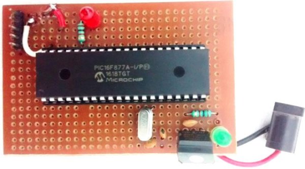
In our previous two tutorials we discussed How to Get Started with PIC using MPLABX and XC8 compiler, we have also made our First LED Blinking Program with PIC and verified it by simulation. Now it’s time for us to get our hands on to the hardware. In this tutorial we will build a small circuit on a Perf Board for Blinking the LED using PIC. We will dump the program to our PIC microcontroller and verify the LED Blinking. To Program the PIC MCU we will be using MPLAB IPE.

LED Blinking with PIC Microcontroller

LED Blinking with PIC Microcontroller

Materials Required:

As discussed in our previous tutorial we will need the following materials:

  • PicKit 3
  • PIC16F877A IC
  • 40 – Pin IC holder
  • Perf board
  • 20 MHz Crystal OSC
  • Female and Male Bergstick pins
  • 33pf Capacitor – 2Nos, 100uf and 10uf cap.
  • 680 ohm, 10K and 560ohm Resistor
  • LED of any color
  • 1Soldering kit
  • IC 7805
  • 12V adapter

What happens when we “Burn” a Microcontroller!!

It is a usual practise to upload the code into a MCU and get it working inside the MCU.

But what really happens inside the MCU how does few lines of C-Program get into a silicon chip and gets executed?

In, order to understand this lets have a look at our program

LED-blinking-with-PIC-microcontroller-program

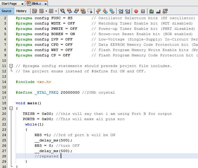
As we can see this code is written in C-Language and it will make no sense to our MCU. This is where the part of our compiler comes in; a Compiler is one which converts this code into a Machine readable form. This machine readable form is called the HEX code, every project that we create will have a HEX code which will be in the following directory

 **Your location**\Blink\Blink.X\dist\default\production\Blink.X.production.hex

If you are so interested to know how this HEX code looks like, just open it using the notepad.  For our Blink program, the HEX code will look like the following:

Since we have just compiled a small LED blinking program, the memory summary shows that we have just consumed 0.5% of the available program space and 1.4% of Data space.

Memory of the PIC16F877 microcontroller is basically divided into 3 types:

Program Memory: This memory contains the program (which we had written), after we’ve burned it. As a reminder, Program Counter executes commands stored in the program memory, one after the other. Since we have written a very small program, we have consumed only 0.5% of the total space. This is a non-Volatile memory, means the stored data won’t be lost after the power off.

Data Memory: This is RAM memory type, which contains a special registers like SFR (Special Function Register) that includes Watchdog timer, Brown out Reset etc. and GPR (General Purpose Register) that includes TRIS and PORT etc. The variables that are stored in the Data Memory during the program are deleted after we turn off the MCU. Any variable declared in the program will be inside the Data memory. This is also a volatile memory.

Data EEPROM (Electrically Erasable Programmable Read-Only Memory): A memory that allows storing the variables as a result of burning the written program. For example if we assign a variable “a” to save a value of 5 in it and store it in the EEPROM this data will not be lost even if the Power is turned OFF. This is a non-Volatile memory.

Program Memory and EEPROM are non-volatile memories, and called as Flash Memory or EEPROM.

ICSP (In Circuit Serial Programming):

We will be programming our PIC16F877A using the ICSP option that is available in our MCU.

Now, What is ICSP?

ICSP is a simple way which helps us to program an MCU even after it is placed inside our Project board. There is no need to have a separate programmer board to program the MCU, all we need is 6 connections from the PicKit3 programmer to our board as follows:

1

VPP (or MCLRn)

To enter programming mode.

2

Vcc

Power  Pin 11 or 32

3

GND

Ground PIN 12 or 31

4

PGD – Data

RB7. PIN40

5

PGC – Clock

RB6. PIN 39

6

PGM – LVP enable

RB3/RB4. Not mandatory

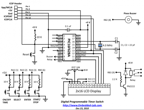
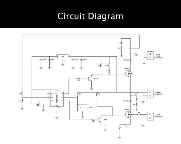
Circuit and Hardware:

Now, we have our HEX code ready and we also know how to connect our PicKit 3 to our PIC MCU using ICSP. So, let’s go ahead and solder the circuit with help of the below schematics:Schematic LED Blinking with PIC Microcontroller

For more detail: LED Blinking with PIC Microcontroller

The post LED Blinking with PIC Microcontroller appeared first on PIC Microcontroller.


An LED Persistance Of Vision Name Badge using PIC16F88

$
0
0

An LED Persistance Of Vision Name Badge

This Instructable shows a name badge that I have built for my daughter.

I have seen the Defcon badges, and thought they were cool. Why cant my kids have one as well – but specially built for them?

So here you go – A simple badge that uses a PIC 16F88, and a handful of LEDs, and flashes your child’s name in lights when they shake it, or push a button.
LED Name Badge
I have left space on the PCB that I designed so that it can support an accelerometer.  It isn’t in this version because I have to order the parts.  This one is created using the bits I had in the garage!

schematic.pdf(595×842) 149 KB

Etch up a board – Make it decorative

The first step it to create the PCB using your favourite PCB package.

You could download my PCB file, but it probably wont work unless your child is named Sian!  Just in case people ask, I have included it as a PDF file.
Schematic LED Name Badge
In Sians case, I created a PCB layout – and made a decorative fill as a background – I think it turned out pretty well!

Here is a photo of Caties board having finished the etching process – I just have to clean the etch resist off the board, and mount the components.

NameBadge-Sian.pdf(595×842) 7 KB

The post An LED Persistance Of Vision Name Badge using PIC16F88 appeared first on PIC Microcontroller.

Writing Your First Program with PIC Microcontroller and Setting up Configuration Bits

$
0
0

This is the second tutorial of our PIC Tutorial Series. In our previous tutorial Getting started with PIC Microcontroller: Introduction to PIC and MPLABX, we learnt the basic stuff about our PIC microcontroller, we also installed the required software and purchased a new PicKit 3 programmer which we will be soon using. Now we are ready to get started with our First LED blinking Program using the PIC16F877A. We will also learn about Configuration Registers in this tutorial.

Writing Your First Program with PIC Microcontroller and Setting up Configuration Bits

Writing the first PIC microcontroller program to blink an LED

This tutorial expects that you have installed the required software on your Computer and you know some decent basics about the PIC MCU. If not, please bounce back to the previous tutorial and get started from there.

Getting Ready for Programming:

Since we have decided to use the PIC16F877A, with the XC8 compiler let us get started with their datasheet. I recommend everyone to download the PIC16F877A Datasheet and the XC8 Compiler manual, as we will be referring to these frequently as we progress through our tutorial. It is always a good practise to read the complete Datasheet of any MCU before we actually start programming with it.

Now, before we open our MPLAB-X and start programming, there are few basic things that one has to be aware of.  Anyway, since this is our first program, I don’t want to harangue you people with lot of theory but we will stop here & there as we program and I will explain you things as such.  If you don’t have enough time to read through all these then just have a glimpse and jump into the video at the bottom of the page.

Creating a New Project using MPLAB-X:

Step 1: Launch the MPLAB-X IDE that we installed in the previous class, once loaded it should look something like this.MPLAB X Writing Your First Program with PIC Microcontroller and Setting up Configuration Bits

For more detail: Writing Your First Program with PIC Microcontroller and Setting up Configuration Bits

The post Writing Your First Program with PIC Microcontroller and Setting up Configuration Bits appeared first on PIC Microcontroller.

LED Strobe for PIC12F629

$
0
0

Description

This project functions as a simple strobe for driving an LED.  The use of an output transistor allows it to pulse the strobe LED with a current up to 100mA.

Four jumpers provide options for changing the pulse width, strobe repeat interval and single or double strobe flash.  The programmer ready code has default timings which are easily customised by editing values in the PIC’s EEPROM at programming time.

This is one of those applications where it’s arguably better than a 555 timer based solution but in practice you could build it with a 555 timer faster than you can write the PIC code.  However it only needs the code writing once, I’ve done that and designed a small PCB too so away you go.

Download schematic in PDF

Circuit Description

The circuit provides a LED strobe function with jumper selectable operating modes.

LED Strobe

The strobe interval can be configured using 4 jumpers for 1,2,3 or 4 seconds; strobe on time of 30mS or 100mS and single or double strobe pulse. 

Since the PIC can only supply 25mA from its I/O pin a transistor is used to increase the maximum current driven through the LED.  This transistor has a maximum collector current of 100mA which is adequate for driving most types of 5mm LEDs.  The PIC could be used to control a higher powered output switch if desired.

The value of R3 series current limiting resistor for the strobe LED has been selected on the conservative side rather than providing maximum brightness.  With a 5 volt supply and LED with 1.8V forward voltage yields current of approximately 47mA.

The strobe LED can either be installed on the PCB in position LED1 or off-board via connector CN2.  If the off-board option is used do not install a LED into position LED1 on the PCB.

LED2 is a monitor LED, if the off-board strobe LED is used, this LED can be useful for monitoring the operation of the circuit.  If you don’t want this option, just omit LED2 and R4.

Capacitor C1 is used to decouple the 5 volt power supply rail.  If you are building the circuit on a breadboard or stripboard you should ensure it is located close to the PICs Vdd connection (pin 1).

The input voltage must not exceed 5 volts.  It can run from as low as 3 volts but you will need to modify the Strobe LED resistor value.  Also be aware of the LED forward voltage; some high brightness LEDs and in particular white LEDs and some blue and green LEDs have forward voltages in excess of 3 volts.

The operating modes are selected by using jumper block JP1.  If you are building the strobe for a specific application you may want to hardwire inputs to ground as required rather than fit the jumper pin header. 

Choosing R3 / LED1

Obviously we want the strobe LED to be as bright as possible.  It is important that the series resistor R3 is chosen so that the LED current does not exceed the manufacturers rating.  Since different LEDs have different maximum forward current and voltage ratings you must select this resistor to suit the specific LED you are using.

For other LEDs you can use this site to calculate the resistor needed http://led.linear1.org/1led.wiz  When you go to this site it asks for the source voltage.  This will be 5 volts, or if you’ve used batteries to power the strobe, the total battery voltage.  Also note that driver transistor Q1 is only rated to 100mA so do not exceed this even if the LEDs used can.

Strobe Operating Modes

The section refers to the default timings used in the programmer ready firmware download.

The pulse width, interval and strobe mode are user selectable using the JP1 jumper block.  There are two strobe modes, single and double pulse.  The double mode has a (default) 175mS off-time between the two pulses.  As shown in the diagram below, the interval is measured from the end of one pulse group to the start of the next group. 


For more detail: LED Strobe for PIC12F629

The post LED Strobe for PIC12F629 appeared first on PIC Microcontroller.

Using Push Button Switch – MPLAB XC8

$
0
0

I hope that you already go through the first tutorial of MPLAB XC8, Getting Started with MPLAB XC8 – LED Blinking. In that tutorial we learn how to use an output pin by driving an LED. In this we will learn how to read an Input pin using a push button switch. We already seen that TRIS register is used to set direction of each IO pin, ie Input or Output and PORT register is used to read or write status of an IO pin. 1 at TRIS bit makes the corresponding pin Input while 0 at TRIS bit makes the corresponding pin Output.

Using Push Button Switch – MPLAB XC8

Push Button Switch

An Input pin will be in Hi-Impedance state.Writing 1 to PORT bit corresponding to an Output pin makes the pin Logic High (VDD) while writing 0 to PORT bit makes the corresponding Output pin Logic Low (VDD). PORT register can be used to read physical state (actual voltage level) of an input pin. If an Input pin is at a potential near to VDD, reading PORT bit will give 1 and if the input pin is at a potential near to VSS, reading PORT bit will give 0.

In this tutorial a push button switch is connected to a pin declared as input (TRIS bit 1) and an LED is connected to a pin declared as output (TRIS bit 0).  When the switch is pressed, the LED will glow for 3 seconds.

Circuit Diagram

Schematic Using Push Button Switch – MPLAB XC8

Using Push Button Switch – PIC Microcontroller

VDD and VSS of PIC Microcontroller is connected to +5V and GND respectively to provide the necessary power for the operation of microcontroller. 8MHz crystal is used to provide necessary clock for the operation of microcontroller. Pin RD0 (PIN 19) is declared as an input pin (TRIS bit 1) to which push button switch is connected. Pin RB0 (PIN 33) is declared as an output pin (TRIS bit 0) to which LED is connected. A 10KΩ PULL UP resistor is used along with push button switch to ensure that RD0 is at Logic High (VDD) when the switch is not pressed. Whenever the switch is pressed, RD0 becomes Logic Low (VSS). A 470Ω resistor is used to limit the current through the LED.

For more detail: Using Push Button Switch – MPLAB XC8 

The post Using Push Button Switch – MPLAB XC8 appeared first on PIC Microcontroller.

LED message system on a Strida folding bicycle wheel using PIC12F675

$
0
0

LED message system on a Strida folding bicycle wheel

After I’ve bought my strida folding bicycle, one of the first things I’ve done was to check out instructables.com for any strida related projects. And quite astonished to see that there wasn’t any.

So I’ve planned to make an instructable that can be used on my (and also others’) strida.

I think this is the first (and only so far) project in instructables, which is built around the strida.

Though my expertise is electronical engineering and solar lighting systems, I’ve chosen to build a propel light for the strida. The improvement to the other propel lights around the web is to use solar power and to create a totally independent light system that “lives” inside the strida wheel. There is no wires to the outside world and no need to charge either.

The image generated is much better than the shaky photo below 😉

LED Message System

Electronical preparations

For the electronics, you may either go for scratch building or using some parts of a cheap solar garden light. I’ve done both ways. I’ve used this solar light that was wandering around my terrace for 2 years, one of which it was out of order.

I’ve disassembled it and found out it has perfectly good parts for this project.

first of them was a round solar panel. There is no fork in the unique strida bike design neither at the front nor rear. The folding ability is dependent on the magnet which connects the front-rear wheel axises. I’ve widened the small hole in the middle of the round solar panel wide enough the magnet mechanism of the strida wheel. By putting the solar panel in the middle, I also eliminated the balance problems of the wheel.

There are all kinds of small solar panels in these solar lights available everywhere. I guess finding a round solar panel which has got enough empty space in the middle which is enough wide to house the strida wheel axis is hard. But any other panel is ok too. all you have to do is obtain a power source which is able to deliver around 2.3v open circuit voltage and 50-200mA short circuit current. Mine is delivering 2.3v and around 200mA. its really perfect, a very lucky find.

Circuitry

I’ve designed a simple solar lighting circuit. It has got a small microcontroller a very simple charge controller and a voltage multiplier. The part at the lower left of the schematic is the voltage multiplier. It transforms the voltage generated by the 1.2V nimh cell to almost 4V which is enough for the ultrabright LEDs to run properly. The PIC12F675 microcontroller can work with voltages 2-6V so it is not problematic.

some of the solar garden lights have an internal voltage doubler too. Mine has got one too. But I’ve sticked to the circuit schematic. If you find one in your solar light, then you can use it instead of the one in the schematic. All you have to do is open circuit the LDR (light sensor, if there is any). I’ve did that to the doubler I’ve took from the disassembled light and put it a side for further use.
Schematic of LED Message System
Next thing is to assemble the circuitry on multi holed prototype board. This will require some soldering and electronics assembly skills. I’m sure there are many instructables around this subject. You may take a look at them so I’m not mentioning about the assembly here. The photos are of the first light I’ve tried. It had 10 ordinary LEDs. I’ve designed a resistor network method for driving 10 leds with a controller having only 5 output pins. The method increased power consumption so I’ve gave up that. Later I’ll make a second version with a bigger controller and 10 or more LEDs. This version of the circuit has got 5 LEDs.

The circuit is secured to the air valve of the tire. I’ve used a metal valve cap and used hot silicone to glue circuit to the cap.

The proteus simulation file (demo is available on labcenter.co.uk ) is also included for the ones who want to see the circuit working.

Current Project / Post can also be found using:

  • microc0ntroller based led projects

The post LED message system on a Strida folding bicycle wheel using PIC12F675 appeared first on PIC Microcontroller.

Aurora 48 – 48 RGB LED Sequencer using PIC24FV16KA304

$
0
0

Aurora 48 is a compact and thin profile full-color LED sequencer. It’s built entirely with surface mount components, so the profile is nice and clean.

Aurora 48 - 48 RGB LED Sequencer using PIC24FV16KA304

Features

  • Capable of individually controlling 48 Full color LEDs.
  • Each LED can be faded in 7 bit per channel – 2,097,152 colors.
  • Gamma corrected brightness curve for very smooth fades.
  • Simple, one button control.
  • 11 sequence pattern (as of firmware version 1.0).
  • Compact – 2.68 inch (68 mm) in diameter.
  • Thin profile construction (0.137 inch (3.5 mm) thick).
  • No leads sticking out on the back. Ideal for wearable projects.
  • Firmware is easily upgradable via 5 pin ICSP connection.

Circuit

Aurora 48 is capable of individually controlling 48 Full color LEDs using a 40 pin microcontroller. The principle of operation is based on my other “Aurora”s. (see Aurora 9×18)
aura_schematicThe circuit is relatively simple and straightforward. If you’ve seen other LED matrix type circuit, this should look familier.In a nutshell, the 48 RGB LEDs are divided in two groups, connected in a 6:1 multiplex fashion, taking R, G, and B as bus lines, and common pin of each LED as column lines. There are two pairs of R/G/B buses. Since there are only 3 PWM outputs available on the controller used, I used a binary decoder IC to multiplex the PWM signal, to drive 6 bus lines. 3 pins are used to select one of the 6 buses, and 24 pins are used to control LEDs’ common pins.The controller activates one bus at a time, outputs a pulse to the LED that should be lit. The actual duration that a particular LED turns on is controlled by the PWM pulse that goes into the binary decoder, 74HC238. The controller sends PWM pulses as short as 62.5 ns to as long as 12,500 ns to control the brightness.

Parts & PCB

Here’s the part list.
  • 24x 68 ohm (0603) (RC1-24)
  • 6x 220 ohm (0603) (R1,3,5,7,9,11)
  • 6x 1k ohm (0603) (R2,4,6,8,10,12)
  • 2x 10k ohm (0603) (R13,14)
  • 4x 0.1uF (0603)
  • 2x 10uF (1206)
  • 6x MMBT2222A
  • 1x PIC24FV16KA304
  • 1x 74HC238
  • 48x PLCC4 RGB LED (common-anode)
  • 1x Tactile Switch

Assembly

Assembly is very much straightforward, that is if you are familier with surface mount soldering. Please don’t be discouraged – surface mount soldering is not difficult and can be done without special equipment. There are many instructables and YouTube how-to videos showing how to solder SMDs. With a little practice you can solder SMD very easily.Since the PCB doesn’t have silkscreen indicating the parts, use the part placement guide provided to locate the spots for the parts.Start with the center of the PCB and move outwards – 74HC238 and PIC24FV16KA304 would be the first ones to solder. Be sure to apply good amount of flux to the parts to be soldered. Move on to resistors, capacitors, transistors.

The post Aurora 48 – 48 RGB LED Sequencer using PIC24FV16KA304 appeared first on PIC Microcontroller.

The simple Joule Thief

$
0
0

The Joule Thief is such an easy and simple device, but what it does is amazing. It can use a battery that is not usable in any other electronic device and give it life again. It can even take a battery that won’t even power a basic LED by itself when it is brand new (1.5 volt AA) and amplify the power so that it can.
The simple Joule Thief
This “Joule Thief” circuit, using a battery that won’t work in any other device, can power a blue or white LED for approximately 8 days straight before it stops working. It could probably power a red LED for at least 10-12 days. You could also use it to power a microcontroller (such as an AVR or PIC MCU).

This is an entry in the LED Contest with Elemental LED and the Hurricane Lasers contest, so if you like it, vote!

Step 1: Why is it called a Joule Thief?

The reason the Joule Thief is called what it is is because of what it does. (That sentence was confusing) (:

Basically, what the Joule Thief does is it “steals” every last Joule of energy from your batteries. The explanation of what a joule is can be found on the Wikipedia page here. The quickest explanation I can think of is that a Joule is a form of energy that, in the way we use it, can be used to power electrical devices. I won’t go into any more detail here because it gets very complicated.

Step 2: Parts list

Major Components in Project

To make this “Joule Thief”, you will need:

1x 470uH inductor (looks like a fat resistor)
1x 2.2K resistor
2x 1K resistor
2x basic NPN transistor (2N3904, 2N2222, 2N4401, etc.)
1x 1000pf (same thing as 1nf or 0.001uf) ceramic capacitor
1x AA battery + holder (or any other 1.5 volt battery)
As many LEDs as your heart desires.

Step 3: Make it on a breadboard!

Make it on a breadboard

It is super simple to make on a breadboard because it has such a low parts count. Look at the schematic to figure it out.

Step 4: Make it permanent!

I have included the .sch and .brd files for making your own PCB. You can send the .brd file to the OSHPark website here, and they will make 3 copies of the board for $2.30 with free shipping. Not even kidding, it’s that cheap.


For more detail: The simple Joule Thief

The post The simple Joule Thief appeared first on PIC Microcontroller.


LED Christmas Cards using PIC 10F200

$
0
0

This is an instructable on how to build an LED Christmas card using the PIC 10F200 microcontroller.
As this PIC has six pins and is the size of an SMD transistor, it is ideal for low profile applications and can easily be reprogrammed as and when needed.
In this case I am using the “reverse polarised LED” trick to get six LED’s working from three I/O lines, as detailed in Microchip’s “Application Notes”.
LED Christmas Cards using PIC 10F200
Runs on two 3V cells, as the PIC’s maximum voltage is around 7V this is acceptable and the cells last a lot longer this way.

can be used with any of the 10F20x series but you may need to modify the code slightly.

Have fun, -Andre

Step 1: Program the PIC(s)

I’ve used the K182 programmer here, in order to make prototyping easier I soldered a 10F200 to a carrier PCB (cut down from inside an old Sony battery pack) and then soldered wires to this.

Note that this PIC requires ICSP, which means if your programmer doesen’t support this then you will need to find one that does. External 5V is needed, here it is provided from a 9V battery and 7805 regulator.

Step 2: Wire up the PICs

Having programmed the PICs, you will now need to connect them to the wires. I used the individual strands from some cable for this (about 30ga), and first tinned the PIC’s leads, then soldered a wire to each pin. A pair of tweezers with a locking function is very useful for this, as you can hold the PIC securely while soldering.

Its also possible to program the PICs once they are soldered in this way.

You will need a prototyping board and some component leads for this step, wind the wire(s) round the component leads and connect to the correct leads on the programmer.


For more detail: LED Christmas Cards using PIC 10F200

The post LED Christmas Cards using PIC 10F200 appeared first on PIC Microcontroller.

Toggle/Blink led on specific delay with pic microcontroller using timers: MPLABX and xc8 compiler

$
0
0
This is advance tutorial on blink/toggle led with pic microcontroller. In this tutorial i am going to teach you how to toggle led on specific delay. This tutorial is not limited to only toggling led, it can be utilized at many other places. Like generating an event after specific delay, triggering a signal after specific time, reading data on known intervals, outputting data after desired time delay, pwm(pulse width modulation) signal generation, servo motor control etc. The algorithm discussed in the tutorial/post/project can also be used to output a desired frequency signal, by converting time domain signal in to frequency domain.

In the previous tutorial we discussed about how to generate a specific delay using internal timers of pic microcontroller. We also derived and discussed the formula for calculating the output signal period. We also discussed the terms related with the time/frequency formula derivation, such as Tick_counter frequency, Timer Count etc. This tutorial is in chain with the previous one the code used below in inherited from the previous tutorial. I recommend to first go through the previous simple tutorial. You can easily understand the code below if you take the tutorial

Now you have taken the above tutorial its time to start with this tutorial. Suppose we want to toggle an led, generate and event or read data after after 10 ms with 20 Mhz clock source and prescaller set at 1:4. For this we have to calculate the “Timer Count” value. Lets start deriving the “Timer Count”. The formula is given below.

Specific delay formula for Pic Microcontroller’s

10 ms = Timer Count * ( 4 / (20M hz/ 4) )
10 ms = Timer Count * ( 4 / 5 Mhz)
10 ms * 5 M hz = Timer Count * 4
50 k = Timer Count * 4
50000 / 4 = Timer Count
Timer Count = 12500 (Hex 0x30D4)

Timer register value comes out to be 12500(0x30D4) for the above given data. 0x30D4 is a 16-bit value which we have to load in the timer TMR register. TMR register is devided in to two 8-bit registers TMRxH and TMRxL register. TMRxH is timer high byte load the high byte in it, in our case its 30. TMRxL is timer low byte timer low byte is loaded in it, in our case its D4. x denotes the timer we are going to use. Pic base series microcontrollers generally have 3 timers Timer-1, Timer-2 and Timer-3. So if we are using Timer-1 in our project than the statements will look some thing like this
TMR1H = 0x30;
TMR1L = 0xD4;Schematic Toggle-Blink led on specific delay with pic microcontroller using timers MPLABX and xc8 compiler

I am going to toggle the led’s connected to Port-B of pic16f887 microcontroller. Port-B is an 8-bit port. 8 led’s are connected with port-b. Whole port is going to be toggled after 10 ms delay. An external 20 Mhz crystal is used as input clock source to pic16f887 microcontroller. Led’s at port-b are connected in series to a 330 ohm resistor. Timer-1 of pic16f887 is used for generating specific delay. Timer-1 is used in 16-bi mode. Circuit diagram of the project is given on the left side.

Project code is written in mplabx ide and xc8 compiler is used for compiling code. The function Timer0Delay in the code contains 10 ms delay generation logic.

The post Toggle/Blink led on specific delay with pic microcontroller using timers: MPLABX and xc8 compiler appeared first on PIC Microcontroller.

Using Multiplexed 7 Segment Displays – PIC Microcontroller Tutorial

$
0
0

A four digit seven segment display.

The image above shows a four digit seven segment display. These type of displays are widely used to present numerical data to users. Example includes clocks, panel meters, microwave ovens, refrigerators etc. As you can see in a four digit displays there are a total of 4 x 7 = 28 segments (made of leds) so you may think that they will require lots of i/o pins of MCU. But in reality a small trick can greatly reduce the number of i/o pins required.Using Multiplexed 7 Segment Displays – PIC Microcontroller Tutorial

The trick is to activate only one digit at a time. All the segments of each four digit are connected in parallel and common of each four digit is tried to MCUs i/o port via transistors. That means MCU can select any digit and put the segment data which drives the segments. Only the selected digit will light up. Then next digit is selected and segment data is changed according to the digit that must be shown in that place. Similarly each digit is selected and shown. This is done fast enough that the human I cannot see the movement. We can see all four digit lit at the same time as shown in the figure above.Schematic Using Multiplexed 7 Segment Displays – PIC Microcontroller Tutorial

Multiplexed Seven Segment wiring

To display any four digit number, say 1234 on the display. The following steps are taken.

First the display 1 is select by making SEL1 line high (keeping all other SELx line low), now any segment data sent from MCU will be visible only on DISP1. Now we send the segment data for ’4′, thus it is shown on the DIGIT1.

After some time we select digit 2 by setting SEL2 line high (keeping all other SELx line low) and sending segment data that shows ’3′ on display. ’3′ is shown on DIGIT2

After some time we select digit 3 by setting SEL3 line high (keeping all other SELx line low) and sending segment data that shows ’2′ on display. ’2′ is shown on DIGIT3

After some time we select digit 4 by setting SEL4 line high (keeping all other SELx line low) and sending segment data that shows ’1′ on display. ’1′ is shown on DIGIT2

we repeat the above steps. And we do so fast enough that human eye cannot catch the trick and see all four digits lit at the same time.

Implementing it using PIC MCU

We will use PIC18 series MCU to implement the above technique. To make the refreshing of display automatic we will use TIMER0 module. We set it to interrupt on overflow. If you are new to TIMERs and PIC Interrupt handling please see the following tutorials.

Timer Interrupt Service Routine(ISR) is automatically called by the hardware at specified interval. This ISR switch to next display and changes the segment data according to the digit to be show on that display. If it is on last display it switch back to display number 1. The data that is shown in the display is store in an array named digits[4]. You can modify the digits[] to change the display. For example if you want to display “1234” you need to do the following :-

For more detail: Using Multiplexed 7 Segment Displays – PIC Microcontroller Tutorial 

Current Project / Post can also be found using:

  • led name board circuit using pic

The post Using Multiplexed 7 Segment Displays – PIC Microcontroller Tutorial appeared first on PIC Microcontroller.

Low Cost Solar Lighting Controller

$
0
0

Solar Lighting Controller based on PIC12F675 micro controller to be used with a Solar Panel, Battery and a LED 12V Light, it has built with affordable materials and its ready to use, just plug your devices and its done, this controller will function by itself with no need to turn on or turn off the LED Light or press a button for starting to charge its battery due to its program to do it autonomously.Low Cost Solar Lighting Controller

Materials

  • 1-1K ¼ Watt Resistor
  • 4-2,2K ¼ Watt Resistor
  • 2-4,7K ¼ Watt Resistor
  • 5- 10K ¼ Watt Resistor
  • 1- 3,3K ¼ Watt Resistor
  • 1-50K Trimming Potentiometer
  • 3-100nF (0,1uF) Capacitors
  • 2-22nF 25V Capacitors
  • 2-MBR1660 Schottky Barrier Rectifier
  • 4- Green LED Diodes
  • 2-BC547 Transistors
  • 2-IFR5305 MOSFET
  • 1-PIC12F675 Microcontroller
  • 1-7805 Voltage Regulator
  • 1- 8 Pin Base
  • 1- Aluminum Heatsink
  • 5- Insulation Composite TO-220 with M3 Screw Insulation Cap TO-220
  • 3- Terminal Wire Connectors
  • 3-20mm PCB Fuse Holders
  • 3-20mm 5 Amp Fuses
  • 1- PCB Board (4.3” x 4.3”) or 2 830 Points Protoboard
  • 5”- of Solid Core Wire (Red) for PCB Board or 4mts of Solid Core Wire for Protoboard (Black and Red, 4mts p/color)
  • Couche Paper (1 or 2 sheets).

Tools:

  • 1- Electric Wire Cutter
  • 1- Electrical Pliers
  • 1- Soldering Iron
  • 1- Soldering Flux
  • 1- Soldering Tin
  • 1- Solder Sucker
  • 1- PCB Drill
  • 2- Screwdrivers (Plus and Plane)
  • 1- Iron
  • 1- Used Cloth
  • 1- Plastic Recipient (for PCB Board)
  • 1- Ferric chloride Acid for PCB
  • Stainless Steel Scouring Pad
  • Some Water

Software and Hardware:

  • PICkit 2
  • MikroC (Only if you want to modify some code)
  • Microcontroller Programmer

Step 2: Circuit DiagramSchematic Low Cost Solar Lighting Controller

The very first step you need to do it’s look at the circuit diagram, this is the way you will connect your components to function properly. If you are using just a protoboard with some wires just peel some strings and connect. But if you are using a PCB Board go to the next step. I put some datasheets from the less common components to make it easy for you.

If you´ve decided to make a PCB Board follow this step, to get this complete, we need to do 5 things:

  1. The first thing is print the circuit, don’t worry I attached a PDF file with it, you must print it in a Couche sheet.
  2. The second thing is iron the circuit into the PCB Board, just put the Couche paper into the copper side of the PCB Board and adjust to fit properly, when you see that circuit’s tracks are sticking to the PCB Board correctly just stop ironing it and put the PCB Board in some water to clean the PCB Board.
  3. After cleaning the PCB Board, put some Ferric Chloride Acid into a plastic recipient with some water, and immerse PCB Board, Ferric Chloride Acid must cover all the surface of the board.
  4. When you only see the circuit’s tracks on the PCB Board remove it from Ferric Chloride Acid, clean the board with some water and sand it with a stainless-steel scouring pad
  5. Finally, you just have to drill the component´s holes.

For more detail: Low Cost Solar Lighting Controller

The post Low Cost Solar Lighting Controller appeared first on PIC Microcontroller.

Running LED dice

$
0
0

Tons of LED dice projects with different output forms have been published online. The most common output configuration in those projects is a 3-1-3 setup (two rows of three LEDs and one LED at in the middle) of seven LEDs, which simulates the actual patterns of dots found on the six faces of a traditional dice. When it is rolled, one or more LEDs are selectively turned on to display a random number between 1 to 6. This project is about a similar LED dice but with a slightly different output form. It uses 6 LEDs which are arranged in a circular pattern and are labeled 1 through 6. They create a chasing effect when the dice is rolled. The chasing effect slows down gradually, and eventually stops at one of the six LEDs. The rolling is done by a gentle shaking of the dice horizontally. The LED dice is powered with a 3V coin cell battery and uses PIC12LF1822 microcontroller to generate a random number and drive the output LEDs.

Running LED dice

Running LED dice

Circuit diagram

The six LEDs are driven through 3 I/O pins of PIC12LF1822 microcontroller using the Charlieplexing technique. Three 100 Ohm resistors are placed in series with the I/O lines to limit the LED currents. A horizontally placed tilt switch (also known as vibration switch) is used to sense the shaking of the dice. A tilt switch is simply a tube with a tiny conductive metal ball that rolls inside it, and has two electrical contacts that are accessible from external leads. When its tilted upright, the ball rolls onto the two metallic contacts, thus short-circuiting them together. The tilt sensor along with a pull up resistor generates an interrupt signal on GP2/INT pin of the PIC12LF1822 microcontroller and the dice is rolled. A power on/off slide switch is also included in the project. In case you forgot to turn it off, the PIC microcontroller will be programmed to automatically go to sleep mode to save the power consumption. A circular shape PCB is designed for this project. The CR2032 battery holder is placed on the bottom side of the PCB, whereas rest of the electronics and LEDs go on the top side. The design files can be downloaded from the link provided at the end of this section.

Schematic Running LED dice

LED dice circuit (click to enlarge)

Firmware

The LED dice firmware was developed using mikroC Pro for PIC Compiler. For simplicity, I used the built-in rand() function to generate a pseudo-random number between 1 and 6. The rand() function in mikroC gives a pseudo-random number between 0 and 32767. It is then scaled to between 1 and 6 through a modulus division by 6 (which gives a remainder output between 0 and 5) and adding 1 to the remainder. I ran the same algorithm on a higher end PIC microcontroller (PIC18F44K22 at 16MHz) and recorded the frequency of the dice output for 100000 rolls just to see how the output distribution looks like. The mean value and standard deviation of the distribution were 16667 and 3207 (19% of mean), respectively. In 100000 rolls, number 3 exhibits the highest frequency, while 4 has the least number of occurrence. The distribution of outcome was not very impressive (that’s why it is called pseudo-random), but it should work for this basic dice project. Here is the output for 100000 rolls.

For more detail: Running LED dice

The post Running LED dice appeared first on PIC Microcontroller.

LED Infinity Mirror Controller, 32 LEDs, Multiple Patterns using PIC12F675

$
0
0

LED Infinity Mirror Controller, 32 LEDs, Multiple Patterns

UPDATE: This kit is discontinued please see the new version, 8 Channel LED Controller v.3, the development files are still available to build this version.

As simple a circuit as can be. A 12F675 controls a high-power shift register, which in turn controls up to 48 LEDs at 20ma per, (~120mA per channel) in 8 channels(groups),

Software controlled patterns create seamless effects from group to group. With 4-state greyscale ( 4 states of LED of brightness ) a vast amount of patterns/effects are possible.

It was designed to go along with my 8″x8″ 32 LED Infinity Mirrors.

A Gallery of all my Infinity Mirrors

A single momentary-pushbutton cycles through the programmed patterns. Comes loaded with 5 patterns, and the ability to add more through re-writing the firmware.

Kits, Including 32 LEDs, colors buyer’s choice, can be bought from my store  at www.ChromationSystems.com

More Updates and Info will be Posted to the 8 Channel LED Controller Webpage

The Eagle Schematics, PCB layout, and Source Code in Assembly can be purchased  all together in a Developer Package.

UPDATE: Code in ASM is available for download below, or on the Main Website

The Schematic, HEX File, and Datasheet are in the ZIP below.

DISCLAIMER: Recreate this project at your own risk.

Infinity Mirror Controller

Parts

UPDATE: This kit is discontinued please see the new version, 8 Channel LED Controller v.3

To Purchase a Full Kit with all the parts, including 32 5mm LEDs. Visit my Store
Also Available with no LEDs Here

Layout all the Parts:
– programmed 12F675 Buy One
– 8 pin socket
– PCB Buy One
– 8 Position Screw-Down Terminal, with 0.1″ (DIP) spacing
– TPIC6C596, high power shift register
– 0.1uf Capacitor
– 16 pin socket
– 10k 1/4w resistor (Brown, Black, Orange)
– 8  resistors, value depends on LED Color Approx: 20 – 40 ohm
– 32 LEDs, choice of colors
– board mount momentary push-button ( kit comes with an extra panel-mount button )
– scrap of perfboard
– Dual-Strand wire, 22 ga
– ~2″ of solid strand for jumping
– 5 volt, 600ma+ PSU Optional: with barrel Jack Buy One

Optional: ( supplied with the Kit )
– panel mount DC jack
– PSU with correct DC Plug

Tools:
– Soldering Iron

Resistors, Capacitor & Sockets

Place the resistors first.

– R1 is a 10kohm (Brown, Black, Orange), 1/4w, it is the pull-up for the push-button switch
Schematic Infinity Mirror Controller
– R2 – R9 are the resistors for the LEDs.
– The values of R2-R9 vary depending on the Color of the LEDs and the amount per channel.
– Depending the resistors may or may not sit flat on the PCB, if they are to big, just place them in like in the images below. Flip every other one so the leads are next to each other.

Place the Capacitor C1 next.

– It is not polarized and can be placed in either way.

Sockets are last, be careful placing them. Make sure all the leads get into their correct hole.
There is a notch in the sockets that should line up with the image on the top-side illustration.

Solder them in securely and watch for solder bridges between pins.


For more detail: LED Infinity Mirror Controller, 32 LEDs, Multiple Patterns using PIC12F675

The post LED Infinity Mirror Controller, 32 LEDs, Multiple Patterns using PIC12F675 appeared first on PIC Microcontroller.

How to drive a lot of LEDs using PIC12F microcontroller

$
0
0

How to drive a lot of LEDs from a few microcontroller pins.

Using the fact that many microcontroller pins have three states (+V, GND, or
“high impedence”, you can drive N*(N-1) LEDs from N pins. So the little 8
pin microcontroller like a PIC12Fxxx or an ATtiny11 can drive 20 LEDs on
its five available output pins, and still have one pin left for some kind of input.

drive a lot of LEDs from a few microcontroller pins

See also http://www.instructables.com/id/Charlieplexing-LEDs–The-theory/

Step 1

20 LEDs on 5 pins

The current crop of low pin-count microcontrollers (6 pins to 20 pins on
the whole package) are attractively priced and ‘cute’, but the question
arrises as to how you can make the best use of those pins for common
applications such as driving LEDs.

A direct-connect approach to driving LEDs consumes one pin for each
LED. A traditional multiplexing scheme where rows of LED anodes are
driven by one set of N pins and each row’s common cathode is driven by
another set of M pins manages to light N*M LEDs with N+M pins.
However, on a processor with only 5 or fewer outputs (as is the case
with most 8-pin microcontrollers), this barely gets you any more
outputs than direct drive.

Step 2

Charlieplexing

Assuming the output pins are actually tri-state-able (active high,
active low, and high impedence (input)) it is also possible to share
the row and column drivers and control N*(N-1) LEDs with only N pins.
One pin is connected to common cathodes of a row of LEDs and driven
low, and the N-1 pins remaining are connected to the anodes and either
driven high to light that column, or left as inputs to leave the LED
off. Maxim calls this technique “Charlieplexing”, and describes it in
(1); Microchip also mentions this in their document (2) (and
implements in on the PICKit 1 board as well.)

(1) “Charlieplexing – Reduced Pin-Count LED Display Multiplexing”
http://www.maxim-ic.com/appnotes.cfm/appnote_number/1880

(2) “Tips ‘n Tricks 8-pin FLASH PIC Microcontrollers”
http://ww1.microchip.com/downloads/en/DeviceDoc/40040b.pdf

(3) Charlieplexing LEDs- The theory An Instructable by rgbphil

Step 3

Putting it to work.

drive a lot of LEDs from a few microcontroller pins Schematic

This drives 20 LEDs from an ATtiny11. An earlier version of this board was
actually built and appears as the main page photo. I’m afraid the picture
of the schematic is pretty hopeless; you need Eagle to tell you which signals
are connected where.

The post How to drive a lot of LEDs using PIC12F microcontroller appeared first on PIC Microcontroller.


LED Microcontroller Debug Module using PIC18F4420

$
0
0

When it comes to debugging a microcontroller circuit, there aren’t a lot of simple options.  Since a microcontroller circuit might have multiple things going on at the same time, measuring voltages with a DMM isn’t an option.  Using an computerized In-Circuit-Debugger solution is expensive and elaborate, and time-consuming to set up.   People often resort to connecting banks of LEDs to the circuit, but this also takes time and if wired incorrectly, might mislead you about the issues you are trying to solve.

Enter the Microcontroller Debug Module (MDM).  It is a device which simply transplants the microcontroller (MCU) to a separate unit, away from the breadboard.  It is connected by a 40-pin ribbon cable to a small PCB which takes the place of the MCU on the breadboard, transposing each pin directly.  No circuit modifications are required for the operation of the MDM.  On the module are 74LS541 8-bit Line Driver ICs which drives indicator LEDs for each of the 8 bits on each of the data ports on the MCU.  This chip delivers current for the LEDs without affecting the pin of the MCU itself.  The pin and the breadboard circuit have no idea the chip is there.

My microcontrollers of choice are PIC18 family 28 and 40 pin PICs which I have designed this unit to be pin-compatible for.  Your unit can be designed for Arduino Atmel chips or any MCU you wish to use.

This Instructable is mostly intended to inspire ideas and some circuit pieces to help you develop a MDM for your own favorite family of MCU.

Also Please note the schematic and board layout are regarding Revision 0.3, it is far more advanced and has numerous corrections/features added to it, compared to Rev 0.1, which is photographed.

PIC Board

Step 1: Schematic Design

The schematic is large but fairly simple and can be broken down into some smaller parts.

  • J2 is the 40-pin PIC socket, which connects pin-for-pin to the 40-pin IDE connector
  • J8 is the 28-pin PIC socket, which will rest in between the 40-pin socket
  • J3-J6 are arranged to form a 20×2 IDE cable connection for connecting the MDM to the PIC substitute board
  • J7 is a header for running the MDM in a stand-alone configuration without power from the breadboard circuit

Each port has a 74LS541 connected to it which buffers and supplies current for 16 LEDs.  A red LED has its cathode connected to the output pin and its anode ultimately connected to a +5V rail, and a green LED has its anode connected to the same output pin with its cathode connected to ground.  The result is that when the PIC pin goes high, the corresponding 74LS541 pin does the same.  When the pin is high the red LED has +5V on both sides of it, and thus will not light, but the green LED has +5V of potential on it now, and will light.  When the pin is low then the red LED now has +5V of potential across it, and the green LED has GND on both sides of it and will not light.  If the pin is rapidly switching from high to low, it will appear as if both LEDs are illuminated.  Both LEDs would appear lit only in the event that the MCU pin is rapidly changing states, or if the 74LM541 has been disabled.

DSW1 is a DIP switch bank that allows the user to disable or enable the LED output ports if they so wish to.  It will reduce the brightness of the port LEDs if you are not using that port for anything, or if the port is being used as an analog input port.  When the pin is Tri-state then both LEDs will light up at 50% brightness.  Due to limitations of the 74LS541, when the MCU pin is displaying tri-state, it will display as high.  The only time that the output of the 74LS541 will go tri-state is when the enable/disable switch for that chip is enabled.

An oscillator is included on the board, and I recommend it be used because the crystal should be as close to the MCU as possible, and it is not a good idea for it to have to go through a ribbon cable to get there.  It might also cause unwanted noise in the rest of the circuit and could affect ADC readings.

an ICSP header is included on the board, and can be enabled/disabled from the MCU pins with SW1.

Please press the “i” symbol at the top corner of each image to view it in full, readable resolution.  Thank you


For more detail: LED Microcontroller Debug Module using PIC18F4420

The post LED Microcontroller Debug Module using PIC18F4420 appeared first on PIC Microcontroller.

Universal High-Power LED Driver with 3D-printable Case using PIC16F1823

$
0
0

*** There’s a firmware update. Please check out! ***

LEDs are taking over conventional lighting every day. High-power LEDs over 1W are becoming more and more affordable, and I wanted to start using them to replace the lighting fixtures around me. However I realize that finding and configuring the power supply was a bit of a pain, since I wanted to use different LEDs in different configurations depending on what the lighting was for. Power supply needs to regulate the current that goes though the LEDs. With higher current that high-power LEDs require, active constant current circuit is the only practical option. Commercially available buck regulators are easy to use, however, they are usually made for a specific current and voltage range. For me that means having to purchase variety of buck drivers.

LED Driver

Also, most of LED drivers lack dimming function, or have poorly functioning dimmers. I think dimming is essential for modern lighting, and I want smooth control of brightness.
So I decided to develop a universal, dimmerable high-power LED controller. It has taken me four months to develop this controller. Although it’s still in development, I think it’s quite useful to all DYI’ers with LED lighting projects.

I made this an Open Source project. Both hardware and software are open – please use, and extend this project and share the knowledge. A 3D printable enclosure as well as couple of LED mounting hardware is also available as Open Source, download-able at Thingverse. Together you can really kick start LED conversion of your household lighting!

Here’s the list of main features:

  • Inductor “switch mode” controller for high energy efficiency.
  • Wide supply voltage range of 5 to 18V (can go higher, but not tested). Great with batteries as well as AC adapters.
  • Up to 20W maximum output power (can go higher with active cooling). (at supply voltage 12V or above)
  • Constant current (pulsed) – configurable up to 3A peak current.
  • Selectable between buck-boost and boost mode.
  • Analog style dimmer control (smooth, flicker-free continuous adjustment)
  • IR remote receiver – controllable via Sony IR remote control
  • Digitally controlled dimming – via external microcontroller including Arduino.
  • Master/slave gang dimming – connect multiple units together and control the dimming from any one of the units.
  • High frequency pulse drive – 32kHz to 175kHz – no flicker even in video!

This circuit is a relatively straightforward implementation of switch mode voltage converter. An inductor works to convert electric energy into magnetic energy, then it converts back to electric energy. By controlling the charge time you can control the output voltage.
My implementation is a bit different from typical boost or buck-boost circuit in that, instead of rectifying the output voltage, the output voltage drives LEDs directly (pulsed drive). This implementation provides a few advantages:

  • Reduced part count.
  • Higher overall energy efficiency (because rectifier has voltage loss)
  • Better dimming characteristic.

In practice, you can connect 1 to 20 LEDs to the controller. Depending on the supply voltage you can choose between buck-boost or boost mode.

Buck-boost mode can supply output voltage lower and higher than the input voltage. However, efficiency suffers at higher output voltage, so boost mode should be used when you need higher output voltage than input.

Boost mode can only supply output voltage higher than input. As LEDs need minimum voltage (usually about 2V per LED) to start lighting, boost mode is effective when supply voltage is below 2 x (number of LEDs).

More on configuration later…

Peeking into the Output

I think looking at the waveforms will give you the best understanding of how this circuit drives the LEDs. As you can see in the picture, the unit is hooked up to an oscilloscope. Using two inputs, output voltage and the inductor/LED current are shown simultaneously.
The squarish wave is the voltage, and triangular wave is the current.
Notice how at the low power/dimmed level, both the current and the duty rate are low. As you increase the power level, both the current and the duty rate increases. This scheme results in a very wide dimming range with minimum color shift.


For more detail: Universal High-Power LED Driver with 3D-printable Case using PIC16F1823

The post Universal High-Power LED Driver with 3D-printable Case using PIC16F1823 appeared first on PIC Microcontroller.

RGB LED Mood Light Standalone PWM controller for RGB LEDs using PIC12F629

$
0
0

This project is an update to the original RGB LED PWM Driver.  The new version allows the use of either 5mm LEDs or the square bodied Superflux / Piranah style LEDs.  The circuit now uses bipolar transistors rather than MOSFETs which make it more suitable for novice constructors and for the first time this project is available as a kit with all parts required to assemble the PCB including the superflux LEDs. (power supply not included)

RGB LED Mood Light

Full schematic and construction details are shown on this page, as well as the firmware download for those who want to create their own effects or build their own version from the schematic.  If you’re not into programming the kit includes a PIC microcontroller pre-programmed with the firmware and a number of mood lighting effects.

Circuit Description

The circuit itself is fairly straightforward.  Diode D1 provides reverse polarity protection for the board in case the power supply is connected backwards.  C1/C2 and IC2 take the incoming 12 volt supply and provide a regulated 5 volt supply required by the PIC microcontroller.

The red, green and blue LEDs are arranged in three parallel strings of three LEDs.  Resistors R1, 2 and 3 limit the current through the LEDs to a safe value when using a 12 volt power supply. The low side of each LED string connects to a BC547 NPN transistor which is used to switch the LEDs on and off.  These transistors are in turn controlled by the PIC microcontroller which drives each of the red, green and blue channel transistors with a PWM signal to control the average brightness of the LEDs.  Switch S1 is used to select different effect sequences.   The firmware program running on the PIC microcontroller is the smart part of the circuit and determines what colours are generated and how they fade from one colour to the next.

The three colours of LEDs are positioned on the PCB in an irregular arrangement to improve the colour mixing effect when placed behind / inside a diffuser such as a frosted glass globe.

The controller uses (RGB) Red, Green and Blue high brightness LEDs that are pulse width modulated (PWM) to vary the intensity of each colour LED.  This allows effectively any colour to be generated with rapid changing strobe effects, fast and slow colour fades as well as static colours.   The data used to set and change the colours is held in an easy to edit file so if you don’t like the sequences provided with it, you can modify the sequence data include file yourself and reprogram with your own sequences. (you will need a PIC programmer and some practical knowledge of microcontrollers and programming if you want to do this.)

The dimensions of the PCB are 50mm x 50mm. 

The PCB supplied with the kit is professionally manufactured thru-plated with solder mask top and bottom and screen print overlay on FR4 laminate with RoHS finish.

If you want to etch your own PCB you can use the artwork above.  Unless you are able to thru-plate your own PCB you will need to solder component leads top and bottom where required. Also look for the single via on the board that will need to be wired through.

The ready made PCB supplied in the kit has through plated holes so this does not apply.

The kit available from the Picprojects On-line store contains all the parts required to build the RGB LED Moodlight.  This includes all the components, quality FR4 double sided PCB, Superflux LEDs and a PIC12F629 microcontroller pre-programmed with the firmware.

12 volt power supply is not included in the kit

A 2.1mm chassis mount DC power jack and 100mm of red/black wire are available as an option


For more detail: RGB LED Mood Light Standalone PWM controller for  RGB LEDs using PIC12F629

The post RGB LED Mood Light Standalone PWM controller for RGB LEDs using PIC12F629 appeared first on PIC Microcontroller.

Programmable digital timer switch using a PIC Microcontroller

$
0
0

Digital timer switches are used to control the operation of electrical devices based on a programmed schedule. This project describes a programmable digital timer based on the PIC16F628A microcontroller that can be programmed to schedule the on and off operation of an electrical appliance. The appliance is controlled through a relay switch. This timer switch allows you to set both on and off time. That means, you can program when do you want to turn the device on and for how long you want it to be remained on. The maximum time interval that you can set for on and off operation is 99 hours and 59 minutes. The project provides an interactive user interface using a 16×2 character LCD along with 4 push buttons.

Programmable digital timer switch using a PIC Microcontroller

Programmable digital timer

Note: (June 30, 2016) A revised version of this project with added new features is posted here.

Circuit Design

The circuit diagram of this project is shown below. A 5V relay is driven by a PN2222 transistor that is controlled by RB3 pin of PIC16F628A. Digital inputs from the 4 push buttons are read through port pins RA2, RA3, RA4, and RB0. The functions of these push buttons are discussed in the operation section below. A standard 16×2 character LCD is used in the project to display the device status, program menu and time. The LCD is operated in 4-bit mode, therefore, only 6 I/O pins of PIC16F628A are required to drive it. A piezoelectric buzzer provides audible tone when the timer is started and stopped. It also beeps when the device is turned on or off. The + 5V power supply for the circuit is derived from a LM7805 regulator IC. The input to the regulator is given from a 9V DC wall adapter.Schematic Programmable digital timer switch using a PIC Microcontroller

In the circuit diagram, the pins 15 and 16 of the LCD are shown open. These pins are available only in those LCDs that have a back light illumination LED. The pins 15 and 16 are the anode and the cathode of the LED. If your LCD has the back light LED, you can connect these pins to the power supply terminals with a 39 Ohm resistor in series. The backlight LED enhances the readability of the LCD display in low illumination condition.

For more detail: Programmable digital timer switch using a PIC Microcontroller

Current Project / Post can also be found using:

  • pic12f675 based led chaser

The post Programmable digital timer switch using a PIC Microcontroller appeared first on PIC Microcontroller.

How to drive an rgb led using PIC16F877A

$
0
0

The RGB LED contains three LEDs encased in one shell: Red, Green and Blue (some contain an extra blue led – as blue LEDs generate less output intensity (candela) per mA). It looks like a single white led except that it has four leads – one for the common ground connection and one for each led.

drive an rgb led

Basic operation

The average current through each of the LEDs determines it’s light output i.e. its contribution to the total output color. So by controlling the average current through each LED you can create almost any other color.

Diffuser

By varying the current through each led you can create almost any other color but at close range you only see the individual colors of each LED.

To see the ‘merged’ color view it from a distance or put a diffuser over it. I used a small piece of baking paper – which is transparent enough to let the light through and opaque enough to diffuse the light from the three LEDs. In a proper design you would use a semi-transparent plastic.

Note: Other projects in the web show the output without a diffuser I think the camera settings merge the light acting as a diffuser (they do – using a digital camera gives the same results i.e. It’s not what your eye sees on the bench).

If you make a sign board using these LEDs you won’t need a diffuser as your eye will not be able to distinguish the individual LEDs (if it’s far enough away – it’s exactly the same as a TV pixel).

How it works.

This project uses puls width modulation to drive each of the leds in the RGB led. By changing the duty cycle of each PWM signal you can control the average current flowing through each led creating any color you want. The limit is set by the resoelution of the PWM (set at 256 steps per channel).

The project relies on persistence of vision to make it appear that the led is continuously driven (the PWM signals must be repeated quickly enough so that you do not see any flicker) at a rate greater than 50Hz (approx). Too slow and you begin to see the led flickering.

PWM Software

PIC micros only have one built in PWM module so you need to create three pulse width modulators in software.

This is fairly easy to do using one of the timers in the PIC micro and all that’s needed is an 8 bit timer for an output resolution of 1/256.

Note: It’s fairly difficult to make it work at 4MHz (it probably can be done in assembler or with more effort in ‘C’). So I chose to use a 20MHz crystal just to make it easier.

For more detail: How to drive an rgb led using PIC16F877A

The post How to drive an rgb led using PIC16F877A appeared first on PIC Microcontroller.

Viewing all 387 articles
Browse latest View live


<script src="https://jsc.adskeeper.com/r/s/rssing.com.1596347.js" async> </script>