Quantcast
Channel: LED Projects - PIC Microcontroller
Viewing all 387 articles
Browse latest View live

LED Strobe for PIC12F629 / 675

$
0
0

 Description

This project functions as a simple strobe for driving an LED.  The use of an output transistor allows it to pulse the strobe LED with a current up to 100mA.

Four jumpers provide options for changing the pulse width, strobe repeat interval and single or double strobe flash.  The programmer ready code has default timings which are easily customised by editing values in the PIC’s EEPROM at programming time.

This is one of those applications where it’s arguably better than a 555 timer based solution but in practice you could build it with a 555 timer faster than you can write the PIC code.  However it only needs the code writing once, I’ve done that and designed a small PCB too so away you go.
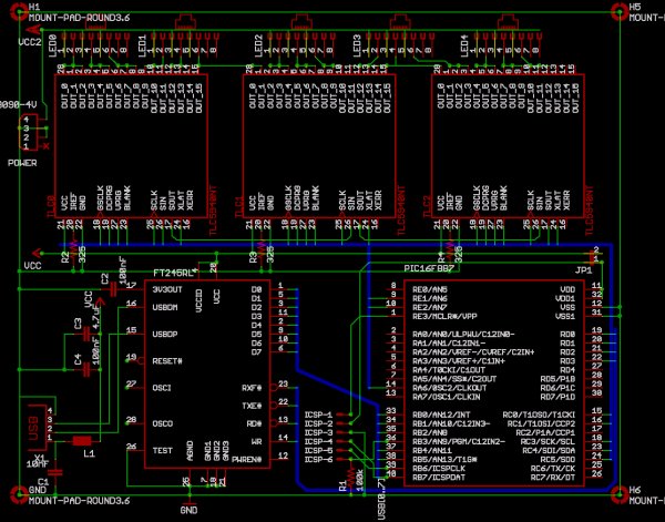
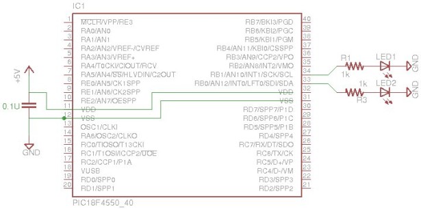
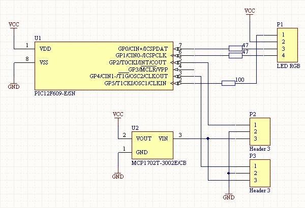
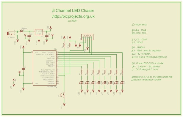
LED Strobe for PIC12F629 675

Schematic

Circuit Description

The circuit provides a LED strobe function with jumper selectable operating modes.

The strobe interval can be configured using 4 jumpers for 1,2,3 or 4 seconds; strobe on time of 30mS or 100mS and single or double strobe pulse.

Since the PIC can only supply 25mA from its I/O pin a transistor is used to increase the maximum current driven through the LED.  This transistor has a maximum collector current of 100mA which is adequate for driving most types of 5mm LEDs.  The PIC could be used to control a higher powered output switch if desired.

The value of R3 series current limiting resistor for the strobe LED has been selected on the conservative side rather than providing maximum brightness.  With a 5 volt supply and LED with 1.8V forward voltage yields current of approximately 47mA.

The strobe LED can either be installed on the PCB in position LED1 or off-board via connector CN2.  If the off-board option is used do not install a LED into position LED1 on the PCB.

LED2 is a monitor LED, if the off-board strobe LED is used, this LED can be useful for monitoring the operation of the circuit.  If you don’t want this option, just omit LED2 and R4.

Capacitor C1 is used to decouple the 5 volt power supply rail.  If you are building the circuit on a breadboard or stripboard you should ensure it is located close to the PICs Vdd connection (pin 1).

The input voltage must not exceed 5 volts.  It can run from as low as 3 volts but you will need to modify the Strobe LED resistor value.  Also be aware of the LED forward voltage; some high brightness LEDs and in particular white LEDs and some blue and green LEDs have forward voltages in excess of 3 volts.

The operating modes are selected by using jumper block JP1.  If you are building the strobe for a specific application you may want to hardwire inputs to ground as required rather than fit the jumper pin header.

Choosing R3 / LED1

Obviously we want the strobe LED to be as bright as possible.  It is important that the series resistor R3 is chosen so that the LED current does not exceed the manufacturers rating.  Since different LEDs have different maximum forward current and voltage ratings you must select this resistor to suit the specific LED you are using.

For other LEDs you can use this site to calculate the resistor needed http://led.linear1.org/1led.wiz  When you go to this site it asks for the source voltage.  This will be 5 volts, or if you’ve used batteries to power the strobe, the total battery voltage.  Also note that driver transistor Q1 is only rated to 100mA so do not exceed this even if the LEDs used can.

Strobe Operating Modes

The section refers to the default timings used in the programmer ready firmware download.

The pulse width, interval and strobe mode are user selectable using the JP1 jumper block.  There are two strobe modes, single and double pulse.  The double mode has a (default) 175mS off-time between the two pulses.  As shown in the diagram below, the interval is measured from the end of one pulse group to the start of the next group.

 Jumper Settings

Customising the strobe timing
The timers for the pulse width, interval and double mode gap are all configurable by editing the values in the PICs EEPROM before writing the HEX into the PIC.  This is nice and easy to do and doesn’t require reassembling the code or anything complicated.  Just load the HEX file from the firmware download section into your programmer application.  Edit the values in the EEPROM as shown below and then write the code and EEPROM data into the PIC.LED Strobe for PIC12F629 675 schematic

Suppose you want a pulse width of 40mS (40 x 1mS) and an interval of 1.3 Seconds (13 x 100mS) you would set the data in address 00 to 28 (40 decimal == 28 hexadecimal).  For the 1.3 second interval change the data in address 03 to 0D (13 decimal == 0D hexadecimal).

Values shown in the example above are the default values in the firmware download.  If you don’t modify them it will uses these timings.

Converting decimal values to hexadecimal

Depending on your programmer the values you need to enter will probably be in hexadecimal, easiest way to convert decimal values to hexadecimal is Google, see example below.  The prefix 0x in the result simply tells us the value is in hexadecimal (hex for short).


For more detail: LED Strobe for PIC12F629 / 675

The post LED Strobe for PIC12F629 / 675 appeared first on PIC Microcontroller.


Misc Projects : High Power RGB LED Controller

$
0
0

This is an ongoing project to control a number (currently 5) of Lamina Atlas high power (350-500mA) LEDs. Current progress includes:

  • PCB artwork (in Eagle) with connections for 5 RGB LEDs.
  • Firmware for a Microchip PIC16f887 microcontroller to interface between the FTDI 245R USB chip and a number of Texas Instruments TLC5940 constant current LED drivers.
  • Python ctypes interface to libftdi.
  • A simple Python interface to communicate color commands by USB
  • Ongoing work includes an intuitive graphical user interface, music synchronization, and a reworking of the hardware to utilize switching constant current regulators.

See 500mA 5-channel RGB LED Controller / Driver, for an updated design.Misc Projects  High Power RGB LED Controller

Motivation

Aside from mere novelty, this project was conceived for a use as a multicolor strobe controller during parties. The current implementation functions yields this, and effective general-purpose room lighting. This naïve implementation achieves approximately 100 frames per second, far in excess of necessity. Effective music synchronization is still in progress, as is a graphical interface.

Hardware

The Lamina Atlas LEDs are rated with an absolute maximum current of 700mA per color, though all output specifications are measured at 350mA. To simplify the number of components, this design uses three TLC5940 outputs in parallel per LED color, achieving 360mA (3x120mA). It is now my understanding that these LEDs are well-rated for 500mA use, but I’ll likely switch to separate amplification for such an increase rather than adding further TLC5940 chips.

All power for devices other than the LEDS is drawn from the USB bus, so do use a powered hub. Though the devices use small amounts of power, I have only eyeballed that the power utilization stays within the USB spec. Input voltage for the LEDS is provided by the 12V line of a standard. I use a computer power supply. Any supply of more than 8-9V should be enough for the maximum forward voltage of the Lamina LEDs and TLC5940 drivers.

Warning: The TLC5940 chips cannot sink as much current as this design would have you believe. While each chip channel can sink 120mA, not all channels may be used at once unless the input voltage is very low. External resistors are required. To remain within the TLC5940 spec, drop no more than about 1V per color channel at maximum intensity. That is, use external resistors, in the 8-15 ohm range in series on each channel until the TLC5940 chip sinks at 1V.

For good measure, I do use a heatsink on the TLC5940 chips. Switching constant current regulators such as the Supertex HV9910 would make the controller more efficient, and resolve this oversight.

I’ve etched only with a single-layer board, with wires on the top layer. If a double-layer board were to be used, a few crossed traces on the top layer would need to be re-routed.

Firmware

This code is written for a 16F887 PIC, though it could easily be ported to other chips. Currently, only one-way (write from computer) communications is functional. Much of the code needed to read is written, though untested.

Functional Overview

A tight loop in main monitors the 245R RD line, indicating new input data. The first byte defined a command, followed by a variable-length set of parameters, which are clocked in immediately. Global state bits are then (atomically) set if, for example, a color update should be performed.

The TLC5940 clocking is performed first by the clkout pin, at OSO/4. Blanking, and all communications with the TLC5940 chips must be coordinated such that commands complete before a blank cycle. These are handled by an interrupt driven by Timer 1. Note that commands are processed only at the next interrupt cycle, introducing some latency.

A few primary commands are fully implemented:

0x02
Raw grayscale data: 16 x 12 bits = 24 bytes ordered MSB first
0x03
Raw dot correction data: 16 x 6 bits = 12 bytes ordered MSB first
0x80
Reset command input. Send 24 bytes to be sure to exit any read loops.
0x81
Disable GIE (global interrupt enable): Halts the BLANK interrupt, disabling the PWM drivers. Turns lights off.
0x82Misc Projects  High Power RGB LED Controller schematic
Enable GIE: Restart the BLANK interrupt, resuming the PWM drivers. Turns lights on.

Only after etching this board did I obtain a Pickit 2 programmer. This programmer allows in circuit debugging, but I had used the ICD pins, RB6 and RB7, for data communications. If RD6 and RD7 are substituted for RB6 and RB7 on the PCB, an ICD can be used. Search on ICD hack in main.c With a little effort in Eagle, PORTD should be substituted for PORTB. Myself, I’ll get around to this when I need another PCB.

FTDI Python Interface

This is a quick-and-dirty Python interface to the libFTDI library. It utilizes ctypes. Only the subset of functions needed for this project are implemented. Others from the library may be easily added.


For more detail: Misc Projects : High Power RGB LED Controller

The post Misc Projects : High Power RGB LED Controller appeared first on PIC Microcontroller.

Throbbing Apple Logo Sticker using PIC10F206 microcontroller

$
0
0

Throbbing Apple Logo Sticker

This little gizmo adds the iconic “sleeping Mac throb” to an ordinary Apple logo decal.
Throbbing Apple Logo Sticker
The idea for this came about when passing by the Apple Store in Palo Alto, California late one night. After hours, when the store is “asleep,” the lighted logos out front pulsate just like the power indicator on a sleeping Mac, and I just about fell over laughing. Unrelated, the following day a friend showed me his new Toyota Yaris, an adorable little economy car whose resemblance to the original “jelly bean” iMac was made even more apparent by the Apple logo decal he’d placed on the back window. The two just screamed to be combined…

Step 1

The Device

Throbbing Apple Logo Sticker 1

I’d been trying to cook up any sort of simple project using one of Microchip’s PIC10 microcontrollers, a minimalist programmable device costing less than 70 cents apiece. Just a few parts are required:

– The microcontroller itself. In this case I used a surface-mount PIC10F206 as it’s what I had on hand, but just about any simple microcontroller will do provided you have the facilities to program it.
– A white LED. I’ve made throbbers using both surface-mount and 3mm through-hole varieties.
– A 3 volt lithium coin cell (CR2032 in this case).
– Battery holder.
– Circuit board to contain the components. Since I was using surface-mount parts, I opted to etch something for the occasion. If using through-hole components, the design is simple enough that a small piece of PCB perfboard with wire jumpers is likely sufficient.
– A clear rubber suction cup; pack of six from local hardware store.
– Glue of some sort. Hot-melt glue, silicone adhesive or cyanoacrylate “Krazy Glue” should all work fine.
– Apple logo decal adhered to a clear glass window.

Two components that typically appear in microcontroller and LED projects are conspicuously absent: there’s no current-limiting resistor for the LED (the lithium watch battery used is intrinsically limited in current), and there’s no decoupling capacitor across the microcontroller’s power leads (simply wasn’t needed in this noncritical application).

Step 2

The Code

Here’s the PIC assembly source code for the project.

The intensity of the LED is varied using pulse width modulation (PWM). Other Instructables and tutorials elsewhere already cover this in much better detail than I could. No offense intended in suggesting searching around elsewhere if you’re not yet familiar with the theory.

The PWM duty cycle does not ramp up and down linearly. Gamma correction creates an exponential ramp that the eye perceives as a near-linear increase in brightness. Because I’m lazy and because so little program space was being used, rather than work out an exponentiation function I simply have a big table of precomputed gamma-corrected values. The PIC10F206 had enough space to contain this table, but a more constrained device might not have this luxury and actual math code will be needed.

One pin from the PIC (GP2) is used for output. This pin was chosen as I might later decide to use this chip’s comparator function (available on pins GP0 and GP1) to detect nighttime or shade and enable the throb only when sufficiently dark. As it is, the device just throbs endlessly when the battery is installed, regardless of environment. The exponential PWM duty cycle means the LED is off most of the time, and a fresh battery can run the device continuously for a couple of weeks.

For more detail: Throbbing Apple Logo Sticker using PIC10F206 microcontroller

Current Project / Post can also be found using:

  • modulated pwm using pic mcu

The post Throbbing Apple Logo Sticker using PIC10F206 microcontroller appeared first on PIC Microcontroller.

Programmable watch with four character display using PIC16F628A microcontroller

$
0
0

Programmable watch with four character display

You’ll be the talk of the town when you wear this obnoxious, oversized, completely impractical wristwatch. Display your favourite foul language, song lyrics, prime numbers, etc.
Programmable watch with four character

Inspired by the Microreader kit, I decided to make a giant watch using similar sixteen segment displays. Twelve hours later, I came out of my masochistic fugue and stopped trying to route a sixteen bit data bus on a single sided pcb small enough to wear on your wrist.

Returning to my digikey box of mystery, I came up with a four character display made up of 5×7 led matrices. 7 bit parallel data input, no need for umpteen current limiting resistors, upper and lower case characters, the rest writes itself.

This instructable is not meant to be a tutorial on creating PCBs or programming PICs. In all fairness, I wouldn’t actually recommend that anyone try to make one of these. If you know enough to follow along, you can probably do a better job than I did. If you don’t know what’s going on, then this instructable isn’t going to teach you all you need to know.

P.S. If you use this to scroll internet catchphrases in public, you are a bad person and should be ashamed.

Step 1: Get your crap together

What you’re going to need:

DLO3416 Intelligent display

Comes in red, green, lavender, fuchsia, and maple walnut flavours.

PIC 16F628A or 16F648A

You might be able to get away with another pin-compatible PIC, just make sure to read the datasheet carefully. Either way, you’ll need at least one PIC in the SOIC package and probably a DIP for breadboarding the circuit. The 628A and 648A are identical except for the amount of program memory available (2k vs 4k). Use the 648A unless you have some 628As lying around.

MCP1253

This is a charge pump dc-dc converter. We’re going to use this to make 5V for our display from a 3V coin cell battery. Get a few so that you can destroy at least one.

The passive components are all through hole type. I know the mishmash of surface mount and through hole is kind of aesthetically displeasing but what can you do.

-Capacitors: 10uF (2), 1uF (1)

-Resistors: 10K (1)

-Switch: N/O momentary pushbutton. The clicky kind you see everywhere cheap buttons are needed.

-Pin headers/sockets: Two pins and a jumper, and a single row of 6 sockets. You can substitute pins for the sockets if you enjoy accidentally tearing clothing and skin.

-CR2032 Coin cell and holder.

Supporting cast:

Soldering iron with the pointiest tip you can find. The MCP1253 comes in a surface mount package small enough to be accidentally inhaled.

Copper clad board, etchant, acetone etc for making the PCB.

PIC programmer with an ICSP header and cable.

Some other stuff without which you won’t get very far but that I can’t remember right now.

Step 2

PCB fun

PCB fun

The display datasheet lies. It says the cursor select is an active high input. Now since we’re patient and careful, we’ve breadboarded the circuit to discover this before wasting hours making PCBs with CU tied low.

With only one display, we don’t need to worry about addressing. We also don’t care about the cursor function. In fact, I have discovered a truly remarkable list of things we don’t care about, which this instructable is too narrow to contain.

I routed the board freehand for the most part, so I’m not including a pretty Eagle schematic. Mapping PIC outputs to display pins is a lot easier using component footprints. If this is too confusing, get stuf.. I mean I’ll make one up.

I’m not going to go over how to make your own PCB, Instructables is made up of about 50% toner transfer method instructions by my count. Download the Eagle file, print it out 1:1 and mirrored. Iron it onto some copper board for about half an hour, pull the paper off, discover that it didn’t work and repeat about ten times.

If you want to do a nicer jumperless job, have a double sided board made or whatever, the Eagle libaries for the MCP1253 (thanks to someone over at Open Circuits) and the display are attached.

Step 3

Assembly

Some general tips:

1. Start with the MCP1253. This way when you screw it up and smash the board, you aren’t losing a lot.

Tin the traces first, then hold it in place and tack it down. The extra trace length around it should help out, heat the far end and line it up. If you have a steady hand and some fine solder you can do the leads individually. If you bridge any, drag some solder wick across them.

2. After soldering the MSOP, the SOIC PIC will be a walk in the park. Same deal again, tack down the corners then work your way around.

3. Surface mount parts go on the bottom everything else goes on top.

The post Programmable watch with four character display using PIC16F628A microcontroller appeared first on PIC Microcontroller.

LED fireflies prototype using PIC12f683 microcontroller

$
0
0

LED fireflies prototype

hello all, heres an attempt i made at something like an LED throwie..the problem (for me) with led throwies is that they just consume their battery, and produce light.. but they could be better at doing both..
LED fireflies

first you have to accept the premise that your willing to spend a bit more for the tradeoff..

the inspiration for this came from some of my other projects, and of course the “LED as a sensor” concept as well as the “LED throwie”

so the parts list:
1 common cathode, tri-color (RGB) LED
1 12f683 pic micro
1 coin cell battery holder

(cheap plug) http://www.makenyc.org/

Step 1: So whats it do?

the idea here is to use the led throwie/graffiti concept, to add a little life to my neighborhood that ive been missing for a long time now… fireflies..

the software is designed to use the LED as a light sensor (so as not to waste power during the day)

the led as an entropy source (to make each firefly unique moments after switching it on) to vary blink color, and rate.

and of course to play a flash pattern every so often in a way that seems “organic” and isnt just an “on/off” blink

and of course use as little power as possible!

(apologies for the darkness of the video, but the light had to be dim enough not to trip the fireflies daylight sensor)

For more detail: LED fireflies prototype using PIC12f683 microcontroller

The post LED fireflies prototype using PIC12f683 microcontroller appeared first on PIC Microcontroller.

RGB LED PWM Driver for High Power 350mA LEDs V3 using PIC12F629

$
0
0

Description

As featured in Electronics Weekly Gadget Freak (20/02/2008)

The main reason I made this version is that I wanted to fit it in to the base of an Ikea Mylonit lamp. This lamp is made entirely from glass and has a small recess in the base with an entry for the power lead.  Since it had nowhere to fit a separate power connector but did have a slot for a power lead to pass in to the base, I needed to make a PCB with a DC power connector in the centre of the board.  At the same time I took the opportunity to tweak the circuit slightly and left out things it didn’t need. The changes are detailed below.  Please note that the original version on the main page is still perfectly okay and you may find the single sided PCB easier to make.

RGB LED PWM Driver

Changes for R3

  • This version uses a double sided PCB. Dimensions are approximately the same as the original version.

  • Removed the second push button switch and components for the RS232 serial interface.

  • Added 22K resistor between MCLR input and Vdd.  This eliminates the need for a jumper on the ICSP header in normal operation. (If you use a 12F683 you can omit this resistor as well since it has an internal pull-up)

  • Provision for a surface mount DC power socket.

  • Removed the power-on LED and series resistor.

  • Added 47K pull-up resistors to the transistor drive circuit.  On the original version, when it first powered on the RGB LEDs would flash at 100% brightness very briefly.  This is caused by the PIC I/O lines defaulting to inputs at power-up and until the software starts and sets them as outputs the PWM inputs to the ZXLD1350 are enabled.  This modification prevents this from happening. NOTE: it’s purely for aesthetics, not a fix for a design fault.

  • In all other respects the circuit and software is identical to the version 2 design on the main page.


Schematic

Version 3 PCB

Construction Notes

You must drill vias and solder links between the ground plane and the top side of the board. These are circled in Yellow.There are also six vias linking tracks on the top and bottom of the PCB. These are circled in GreenYou must ensure you add these or the circuit will not function correctly, if at all.  

The pad size for the three inductors is SM2512.  There are such a variety of inductors that could be used here with so many different footprints.  I’ve left some clear area around the pads to facilitate the use of various inductors but you should make sure that the ones you do use aren’t going to touch other areas of copper.  This may require some creative positioning of the inductors.


For more detail: RGB LED PWM Driver for High Power 350mA LEDs V3 using PIC12F629

Current Project / Post can also be found using:

  • proteus project on led blink fade
  • led pic pro
  • mosfet pwm
  • pic chip led projects

The post RGB LED PWM Driver for High Power 350mA LEDs V3 using PIC12F629 appeared first on PIC Microcontroller.

Infrared (IR) Object Detection Module Circuit Using IR LED and Photodiode

$
0
0

How to make Infrared (IR) sensor Object Detection Module Circuit Using IR LED and Photodiode

The IR Object Detection sensor module is quiet easy to make. This sensor circuit below is a low cost – low range infrared object detection module that you can easily make at home using IR LED’s.

We will use a photodiode and IR LED to make a simple circuit. IR led looks like a regular LED that you usually see in Television Remote controls.For now I have added a regular LED to glow as in indicator when something is detected, you can replace it with a buzzer or something else the way you wish.Infrared  Object Detection Module Circuit Using IR LED and Photodiode

The Main concept is simple, the IR led keeps transmitting IR infrared rays up to some range (there is a potentiometer also in the design with the help of which you can alter the range). When some object comes in the (IR) infrared range, the IR waves hits the object and comes back at some angle, The Photo diode next to IR led detects that IR infrared rays which got reflected from the object and hence works as a proximity sensor. You can read more details about Proximity sensors for more.

The components required to make this IR sensor can be easily found in any electronic stores and it is quiet inexpensive.

IR Sensor Circuit Module Requirements

1 – IR LED TSFF5210
1 – PR (photodiode) BPV10NF
1 – 1k resistance
1 – 220E resistance
1 – 6k8 resistance
1 – 10k potentiometer
1 – IC LM358

Infrared sensor Module Schematics

Following this schematic you can easily make it on a breadboard, I intentionally drew this schematic for this IR sensor this way so that it can easily printed on the copper board in no time if you have some etching solution.Infrared  Object Detection Module Circuit Using IR LED and Photodiode schematic

For now in this circuit an LED would glow as an example. Notice that there are three pins in the schematic in which two pins are used to provide power to the infrared sensor and the Middle pin is unused, and can be used for other operation. The Middle pin goes high (Logic 1) if the photodiode in this object detection module detects an object, and hence can be interfaced with other devices. You can use it the way you wish, it can be used to run some DC motors and make a simple robot. The middle pin of the IR Sensor Circuit can be interfaced with Microcontroller easily to do complex operations,or you can interface an LCD with microcontroller and have the status of the sensor displayed on the LCD very easily as in my next tutorial for interfacing multiple IR Sensors with Arduino and LCD.

For more detail: Infrared (IR) Object Detection Module Circuit Using IR LED and Photodiode

The post Infrared (IR) Object Detection Module Circuit Using IR LED and Photodiode appeared first on PIC Microcontroller.

Using Fixed Voltage Reference (FVR) for A/D conversion in enhanced mid-range PIC microcontrollers

$
0
0
The reference voltage plays a very important role in any A/D conversion. It determines both the range and the resolution (Volt/Count) of the A/D conversion. Besides, the accuracy of the conversion also depends upon how stable the reference voltage is. Usually in PIC microcontrollers, the reference voltage for A/D conversion can be selected as the supply voltage itself or provided externally through one or more I/O pins. But the new enhanced mid-range family of 8-bit PIC microcontrollers have a built-in module that generates a stable reference voltage internally.
Using Fixed Voltage Reference (FVR) for A D conversion in enhanced mid-range PIC microcontrollersIt is called Fixed Voltage Reference (FVR) where the output is very stable and independent of the supply voltage (VDD). The output of the FVR can be configured to supply a reference voltage for A/D conversion internally. This article describes how to configure the FVR module to derive the reference voltage of 2.048 V for A/D conversion in PIC16F1827 microcontroller. The analog signal for this experiment is taken from the output of a LM34DZ temperature sensor. After the A/D conversion, the PIC16F1827 displays the temperature on a 2×8 character LCD.

Theory

LM34DZ temperature sensor

The LM34 series are precision integrated-circuit temperature sensors from National Semiconductors, whose output voltage is linearly proportional to the Fahrenheit temperature. They do not require any external calibration to provide typical accuracies of ±1?2?F at room temperature and ±1.5?F over a full ?50 to +300?F temperature range. The LM34DZ is available in a TO-92 case and the relationship between the linear output voltage and the temperature is 10 millivolts per °F. That is, at 75°F it’s output reads 75 * 10 mV = 750 mV. For full range of measurement, the output of LM34DZ goes from -0.50V (-50 ?F) to 3.0V (300 ?F). We are not using any negative voltage source in this experiment, and therefore LM34DZ won’t be able to measure temperature below 0 ?F. Similarly, on the upper side, the measurement could go up to 300 ?F or less if the  positive reference voltage for the A/D conversion process is less than 3.0 V. Find more details about LM34 in its

PIC16F1827 is a member of Microchip’s enhanced mid-range 8-bit microcontroller family. It is pin-compatible with the popular 18-pin predecessors such as PIC16F628A and PIC16F88, but is equipped with lot more peripherals and other features. The Fixed Voltage Reference (FVR) module in PIC16F1827 generates a stable voltage reference internally. The FVR output provides three software selectable voltage levels, 1.024V, 2.048V and 4.096V. The output can be configured to supply a reference voltage to the following:

• ADC input channel
• ADC positive reference
• Comparator positive input
• Digital-to-Analog Converter (DAC)
• Capacitive Sensing (CPS) module
Using Fixed Voltage Reference (FVR) for A D conversion in enhanced mid-range PIC microcontrollersThe actual generated reference voltage is 1.024 V, but with the help of programmable gain amplifiers, it can be amplified by 1x (1.024 V), 2x (2.048 V), or 4x (4.096 V), to produce the three possible voltage levels. The FVRCON register (shown below) is used to configure the settings for the fixed voltage reference. The bit values of FVRCON register to generate 2.048 V as the positive voltage reference for A/D conversion are shown in blue color font.

Once the FVRCON register is configured, the choice of reference voltage for A/D conversion is made through ADCON1 control register. By setting ADPREF<1:0> bits to ’1′, the positive reference voltage for A/D conversion is derived from the internal FVR module. Clearing the ADNREF bit connects the A/D negative reference voltage pin to the ground (VSS).

Once the reference voltage is selected, the rest of the A/D conversion process is similar to any other PIC microcontroller.


Current Project / Post can also be found using:

  • pic16f77a led projects

The post Using Fixed Voltage Reference (FVR) for A/D conversion in enhanced mid-range PIC microcontrollers appeared first on PIC Microcontroller.


PIC18F4550 Tutorial: Blinking an LED

$
0
0

PIC18F4550 Tutorial: Blinking an LED | Chapter 3

Welcome to my third chapter of this programming tutorial for pic18f4550. From here we will start on programming with pic18f4550, my previous tutorials ( Tutorial 1 and Tutorial 2 ) must have given you some outlines regarding the tools that we need and how to setup the project in details to get started.PIC18F4550 Tutorial Blinking an LED

This is the first method of programming a pic18f4550. For the sake of example, we are going to take a simple case of blinking an LED,  where we are going to blink two led’s on pin RB0 and RB1. In coming chapters we are going to see how to blink the same thing in different ways. Our primary target is to learn various methodologies of Programming same thing in different ways to develop a perfect coding habit.

 Choose the coding method at your own discretion which suits perfect for your project requirement. Remember, the way you code, can save a lot of space.

PIC18F4550 Blink LED – Direct Approach

METHOD-1

First method is a direct and most common approach, where we are going to do all coding in one project file. MAIN.C. Here we are going to use Mplab ide and c18 compiler. It can be also done with Mplab X IDE , where there is no need of C18 compiler as the X8 compiler already includes all the necessary compiler files. However for this tutorial we will stick to Mplab IDE and C18.

Schematic

mentioned before we are going to blink two led’s on port B , RB0 and RB1.  Here is a sample schematic. The code can be easily modified to blink other led as well.

The input voltage must never exceed 5 V or it might damage the microcontroller, you can also use a IC 7805 Voltage regulator or mcp 1702 to ensure the input is 5V.

The circuit can be easily built on a breadboard in no time.

Let’s Start with Coding

-Start MPLAB IDE and create a New Project as explained in the previous post for pic18f4550.

-Add a new file and save it as MAIN.C and save it in the project folder (Don’t forget to Check mark on “ADD to Project file”). You can use any name you wish..

– Now we have a blank empty project with a C file HOME.C

-Then start typing the source code as below.

Some of the sections in the code below are clickable to jump to the code explanation.

 Source Code:

#include<p18f4550.h>                                                // Include Header for PIC18f455

/* ******COMPILER DIRECTIVES FOR CHIP CONFIGURATION BITS ***   */
#pragma config PLLDIV = 5 , CPUDIV = OSC1_PLL2 , USBDIV = 2    // You can write this way
// OR
#pragma config FOSC = INTOSCIO_EC
#pragma config FCMEN = OFF                                 // OR this way
#pragma config BORV = 3
#pragma config WDT = OFF
#pragma config CPB = OFF
#pragma config CPD = OFF

/*  ***************  TIMER *************** */
void delayzz(void)
{              int i, j;
for(i=0;i<5000;i++)
{
for(j=0;j<2;j++)
{           /* Well its Just a Timer */            }    }   }

/* ****************** MAIN ****************** */

void main(void)
{
TRISB = 0 ;                  // PORT B Setting: Set all the pins in port B to Output.

while(1)
{
LATBbits.LATB0 = 1;   // RB-1 to High
LATBbits.LATB1 = 1;   // RB-1 to High

delayzz();

LATBbits.LATB0 = 0;    // RB-0 to LOW
LATBbits.LATB1 = 0;    // RB-0 to LOW

delayzz();

}
}

/* THE END */PIC18F4550 Tutorial Blinking an LED schematic
Download the code main.c or Download the entire Source code as Mplab Project.
Next step is to compile the code.
After the project is built the output files will be dumped into the same project folder, if a separate output folder is not defined for saving all the compiled files.
Now you can use your Programmer to burn the output .hex into the microcontroller.
Code Flow

-Define the header files for pic18f4550.
-Set the Microcontroller configuration settings with “compiler directives”.
-Define PORT settings:- The pins you want to use for blinking. Set the pin to output.
-Then set the timer:- For the time delay in-between the blinks.
-Define Pins to set as ON or OFF with a delay in-between.
-And finally make a loop where the main code will keep executing.


For more detail: PIC18F4550 Tutorial: Blinking an LED

The post PIC18F4550 Tutorial: Blinking an LED appeared first on PIC Microcontroller.

PIC18F4550 Tutorial: Blink LED – 2

$
0
0

Hi welcome to my 4th chapter of PIC18F4550 programming. Here we are going to learn another methodology or technique for programming a pic18f microcontroller which would be helpful in future while dealing with complex coding. We are going to define our own header file. We are also going to see the Source Code and will understand the importance, benefits of programming a microcontroller this way on Mplab ide. In Chapter3, we saw the basic programming template for pic18f4550 which is a very common style of programming. In this programming tutorial we are going to breakdown the same source code into some header files to make things simple.

PIC18F4550 Tutorial Blink LED 2

PIC18F4550: Programming Method 2 -Chapter 4

METHOD-2

In our previous chapter on pic18f4550 programming we did all the coding in just one file main.c for blinking an LED with pic18f4550 which is a very common method adapted by many beginners. However here we are going to break down the same program and define our own header file. For our example we are going to use the same old example of blinking an LED. This strategy of programming helps in long run for beginners.

Why do we need to define an external header file?

For a simple example of blinking or flashing an led it is pretty much okay to code everything in one file main.c. But in future when you are dealing with complex coding functions and logics, things might get messy if all the coding is done in just one file. Rather sometimes it becomes difficult for even the actual programmer to find their own mistakes, or to makes changes if some coding needs to be modified after a couple of months. Hence dividing things makes it easy for keeping the track of code blocks.

For example, the source code in our previous tutorial started with a general programming style where you have the includes in the beginning (#include<p18f4550.h>), and then followed by lengthy Compiler directives (#pragma config) to set the chip configuration bits.

Instead of writing the lengthy chip config bits in the main.c, you can create a separate header file with headername.h and then write all the compiler directives in the header file headername.h. Finally include it the main.c like the regular #includes in the beginning of the code. A typical user created header include syntax would look like..

                                    #include “headername.h” //User defined header

While executing the main.c all the compiler directives will be parsed by the compiler defined inside #include ” headername.h”, In future if you want to change some settings in the chip config bits when without touching the main.c you could directly open the respective header file and make changes.

Creating a Header file

     -Create a new file.

     -Type the compiler directives in the new file created.

     -Save the file with a name and extention “.h”. Example: headername.h

     -Check mark “Add File to project” >> Hit save.

If everything goes well the then you would see your created header file included in the Project Explorer under “Header Files” , if its not showing then probably while saving the file you forgot to check mark “Add to Project Files”.

     -Open main.c and add the line #include ” headername.h “.

By this way you can create your own header files with codes such as compiler directives, timers or port settings and have them included in the main block. The functions defined inside the header files can be also called from main. This strategy would keep the main.c block clean and would also be easy to makes changes with coding in the future. Instead of messing with entire coding you can specifically reach the section you wish to make changes.

Let’s review the schematic and the source code for a example below.

 Schematic

In our previous Tutorial we made two LED’s to blink. Here we are going to blink four led’s on port B , RB0, RB1, RB2 and RB3 .  Here is a sample schematic. The circuit can be easily built on a breadboard in no time.

Source Code: Blinking led Method 2 with header Files

The source code below will blink the led the same way as in previous tutorial, but here I have defined two header files compdirectives.h and ledsettings.h. compdirectives.h contains all the Chip configuration settings And ledsettings.h has all the necessary port settings and timers for blinking the led.PIC18F4550 Tutorial Blink LED 2 schematic

SOURCE CODE : main.

   /*      ****************** main.c ******************      */

#include<p18f4550.h>                                     // Include Header for PIC18F4550
#include “compdirectives.h”                                // User defined header: Chip Config | Complier directivs
#include “ledsettings.h”                                        // Port settings

/*  ***************  TIMER *************** */
void delayzz(void)
{              int i, j;
for(i=0;i<5000;i++)
{         for(j=0;j<2;j++)
{     /* Well its Just a Timer */     }    }   }

/* ****************** MAIN ****************** */
void main(void)
{
setpin();                 // PORT B Setting: Set all the pins in port B to Output
while(1)
{
LED1_on();                    // Glow led 1
LED2_off();                    // OFF led 2
LED3_on();                    // Glow Led 3
LED4_off();                    // OFF led 4
delayzz();
LED1_off();                     // OFF led 1
LED2_on();                    // Glow led 2
LED3_off();                    // OFF led 3
LED4_on();                    // GLow led 4
delayzz();
}
}

/* THE END */

For more detail: PIC18F4550 Tutorial: Blink LED – 2

The post PIC18F4550 Tutorial: Blink LED – 2 appeared first on PIC Microcontroller.

Picaxe Blending Nightlight using pic12f683

$
0
0

I had a few multicolor LEDs laying around and wanted to whip up a color-blending nightlight. I built 2 devices, each in its own 20 pin DIP socket without soldering. A 3-pin header is included so I can reprogram the light on-the-fly if desired. On my first build, I used wire-wrap. The next one used multiple wires pushed into the socket. A bit more difficult, but no wire-wrapping or soldering necessary.

picaxe blendlight led

Parts count:

  • 1 Picaxe-08M microcontroller
  • 4 resistors
  • 1 bi-color LED
  • 1 3-pin programming header
  • misc wire, DIP socket, a battery holder

schematic picaxe blendlight led

My schematic is above. Take a look at the code and you will see that the light blends between 4 random colors somewhere in the available red-green range. The light uses pwm to fade in and fade out. It does its show about once each 30 seconds, but you can reprogram it if you want it to stay on all the time. On a quick check, the current drain is negligible when the light is off, and < 10ma when blending. The batteries should last close to their shelf life.

And this code turns the light on only when it is dark. It uses the LED to *sense* light level and compare it with the level sensed at initial power-on. It also adds 2 flickering modes, kind of like a candle. Even with a very simple circuit like this one, you can do some interesting things.

For more detail: Picaxe Blending Nightlight using pic12f683

Current Project / Post can also be found using:

  • pic based led display
  • pic lighting projects
  • xilinx pic18f4550

The post Picaxe Blending Nightlight using pic12f683 appeared first on PIC Microcontroller.

3-Channel IR Relay Controller with user programmable IR commands for PIC12F629

$
0
0

Description

This project is a 3 channel infrared (IR) remote controlled relay driver.  It works with 12-bit SIRC IR signals as used by Sony remote controls.

The controller also features the ability for the user to ‘program’ the commands it will respond to using  the IR remote control.   Each of the three relay channels can also be individually configured for either toggle or momentary switch action.

Although this project has been designed around the control of three relays, the PIC microcontroller can be incorporated in to any application where up to three logic level outputs are required to be remotely controlled.

Relay Controller

The controller uses Microchip’s low cost PIC12F629 microcontroller along with a handful of

easy to find  components making it cheap and easy to construct.  Everything you need to know to build this project, including the firmware code is right here on the project page.  If you don’t have access to a PIC programmer you can buy the PIC chip pre-programmed from the online-store

Don’t forget to check out the accompanying mini IR remote control which can be used with this project.

Download schematic in PDF

Circuit Description

The board is powered from a 12 volt DC supply input.  This is fed through diode D5 which provides protection from a reversed connection of the power supply. Capacitor C2/C3 filter / decouple the 12 volt supply.  The 12 volt input is fed to a 78L05 voltage regulator to provide the 5 volt supply required for the PIC microcontroller IC1 and the IR receiver IC3.

The IR signal is detected and demodulated by IC3 a TSOP4838 IR receiver IC.  This part was chosen because it has a low supply current requirement – typically around 1.5mA.  The output from the detector is fed to the GP2 input of microcontroller IC1.  When a signal is received by the TSOP4838 it  pulls the GP2 input on the PIC low, when no signal is received it is pulled high by an internal pull-up resistor.   The firmware programmed into the PIC12F629, IC1 decodes the signal using the 12-bit SIRC protocol (see download section).  

n.b. The circuit and code will work without modification using either a PIC12F629 or PIC12F675

The relays are switched on by microcontroller IC1 via driver transistors Q1, Q2 and Q3.  These are low power NPN transistors, in this case BC547 but virtually any small NPN transistor will work here as they only need to switch around 30mA – BC548 or BC549 would also work well.  The relay status LEDs are connected in series with the base of the relay drive transistor. When one of the outputs of IC1 goes high, around 5mA passes through the respective LED and 470ohm resistor to the base of the transistor, causing both the LED and transistor to turn on and activate the relay.  When the output of IC1 goes low, the 10K resistor holds the base of the transistor at 0V ensuring it turns off and the relay deactivates.  The diodes across the relay coils protect the transistor from the back EMF generated by the relay coil when it is de-energised.

LED 4 is a status LED, in normal operation it indicates when an IR command is being received by flashing at 20Hz.  It is also used to indicate that the controller is in setup mode.  Switch S1 is used to enter and exit setup mode, details of this are covered in the User Programming section.

For more information on the SIRC infrared protocol and codes see:

Download PCB artwork in PDF
Download PCB overlay in PDF

PCB dimensions are 80mm x 75mm approx.

Suggested hole drill sizes:

  • terminal blocks and S1 metal frame drill at 1.1mm
  • relays drill at 1.5mm
  • U1, U3 drill at 0.85mm
  • PCB mounting holes drill at 3mm
  • everything else drill at 0.75mm

Component List

You can buy all the parts needed to build this project from most component suppliers world wide. In the UK you can get everything from Rapid Online and I’ve included a parts list with their part numbers below.


For more detail: 3-Channel IR Relay Controller with user programmable IR commands for PIC12F629

The post 3-Channel IR Relay Controller with user programmable IR commands for PIC12F629 appeared first on PIC Microcontroller.

Microprocessors Garland

$
0
0

1. Presentation

For some time now, I think the commercially available garlands, are too boring, too repetitive with their two or three alternations of colored bulbs.

I wanted to create a truly personalized one without ruin me either. Two ideas immediately came:

– a microprocessor to control all the lights, but at the cost of a relatively large strand wire, even though the use of crossing wire and diodes, can reduce the number of son, this is not very satisfactory,

– place a microprocessor per lamp, but until the price of each processor exploded the price of the most basic garlands.

For a short time, Microchip sells very small processors, a few tens of cents the unit, CMS and low number of legs.Microprocessors Garland

Diagram:

The master processor sends control commands over a serial single wire bus. These commands are interpreted and transmitted by each slave unit.

2. LED Modules

a. Electronics

The processor used is the PIC12F609-I/SN for several reasons:

–  Its price € 0.56 including VAT per pack of 100 on tmicrochipDIRECT

–  Its case: 8-pin SOIC

–  The presence of an external interrupt pin and an hardware timer

The serial bus, as opposed to a parallel connection of all processors, was chosen for two reasons:

– This allows the self-enumeration of the slave units: starting the master sends a byte with a value of zero. This value is stored by the first unit, then the value “1” is sent to the next unit. And so on: each unit is taking to address, the value received, and sends that value incremented to the next unit. This avoids to program each unit specifically with a different address.

– On long cable, the resistance of the copper becomes significant. While each unit consumes about 50mA (LED above), after 50 diodes, the total consumption is close to 2.5A. In this case, the voltage reference to the mass change, and the interpretation of 1 or 0 become difficult. With chaining, the signal is regenerated at each hop unit.

Always the problem of current drawn on a string of any length, it is not guaranteed to have the same voltage at the beginning and the end of the garland. The principle is to feed the entire wreath with 7V and one regulator will stabilize to 5V on each unit.


The diode actually consists of three LEDs (red, green, blue) to create all the visible colours. It is supplied with common anode, because the microprocessor has drain capacity to ground greater than to provide +5 V on each bit output.


The intensity control is software (pulse width modulation). Each colour is controlled internally on 64 levels, all refreshed 100 Hz.

The printed circuit board is looking like :

–          On the left the two power connectors and serial bus around the 5V regulator,

–          The processor,

–          The resistors for the LEDs,

–          The connector of the LED.

b. Serial protocole

The transmitted frames are made of 25 bits : 7 address bits + 6 bits red bits + 6 green bits+ 6 blue bits.

Unlike a conventional serial communications, bits are encoded as pulse width, not by voltage level. The objective is to work with interruption, instead of pooling.

The software configures the trigger interrupt on rising edge. When this change occurs, a hardware timer is started and next interrupt is configured on falling edge. When this new event arrives, the timer value is tested to determine the value of the encoded bit. (60μS to “0”, 30μS to “1”). At each interruption, the state is reported as output for the next unit.

The total duration of a bit is 100μS.  With few hundred microseconds between each command, this mean 300 commands per second.Microprocessors Garland schematic

c. Software

3. Master module
a. Hardware

Extremely simple:

–          8F252 I / SP with its 20MHz quartz,

–          Resistor on the MCLR pin,

–          A programming connector,

–          the serial output on PORTBbits.RB1,

–          A 7805 regulator and its capacitor

I used a ready-to-use testing wafer, instead of creating at printed circuit board.

b. Software

4. Documentation
a. Datasheets

Master processor PIC18F252

LED processor PIC12F609

5V smd regulator MCP1702


For more detail: Microprocessors Garland

The post Microprocessors Garland appeared first on PIC Microcontroller.

Motion Activated Led Dice using PIC16F688

$
0
0

Introduction

  I’ve always wanted to build an electronic led dice, but something different from what we see on the internet. Making it motion controlled… now that’s new!   Many new cell phones that have accelerometers built in also have dice games. These dice move when shaking the cell phone. My Led Dice project will also work with a shake motion but without the use of the expensive accelerometers.

shake dice

Parts List

R1                   500 ohms resistor
R2                   500 ohms resistor
R3                   500 ohms resistor
R4                   500 ohms resistor
R5                   500 ohms resistor
R6                   500 ohms resistor
R7                   500 ohms resistor
R8                   10K resistor
C1                   100nF cap
Led1 to 7        5mm flat led
Piezo               Piezo HPE-120
IC1                  16F688 microcontroller from Microchip
S1                    Normal On/Off switch

Others:
Box
AAA x2 battery support
PCB
Spring, screws and wire
Hex program for the microcontroller


For more detail: Motion Activated Led Dice using PIC16F688

The post Motion Activated Led Dice using PIC16F688 appeared first on PIC Microcontroller.

LED dot matrix scrolling message – 14×5 – source code

$
0
0

I have built various scrolling message badges for instance using the 16F57- 10×5 and 12×5. However, since these chips only have a small FLASH, there is not much flexibility. I don’t really recommend these controllers for a scrolling message.

Recently I have started a new project, using small 1.9mm ready made modules, and a 16F884. It has 4K FLASH which is sufficient (about 1/3 are used), and 256 bytes RAM. However, the max. continuous RAM is only 80 bytes.

edit: I am now using 2 RAM banks (160 bytes).

The font is proportional, most characters are 4 pixels wide, some are 3 only, and a few are 5 pixels wide. The complete bitmap is precomputed, which requires a large RAM buffer.

This time I tried something new- mapping all the IO randomly, and connecting the LED matrix to just any IO lines. For this purpose a number of tables are used. Also the TRIS registers are setup automatically.

It works so far, however, right now the text is not scrolling. However, this is only a minor additional effort. Also it turned out one module is common anode, the other common cathode, so two sets of tables are required. It is actually easy to correct the layout using these tables.

Table 1 is simply the order of the anodes and cathodes according to the datasheet.

The second table contains pointers to PORT variables, on correlation to the pin numbers in table 1, and in ascending order. The third table contains bit masks to set/reset individual bits (actually distributed over random ports). Also there is a table for the TRIS pointers for automatic setup.Led dot matrix scrolling message source code

here you can see the SMD microcontroller, mounted on adapter PCB. The modules are simply soldered directly into the adapter board- this works, since random IO is possible via software.

The LED matrix! It works correctly, the bitmap is copied from the display buffer. In order to scroll the complete bitmap, it is just neccessary to slide a window from the scroll bitmap.

The scroll is generated using the font table, and one of the preprogrammed texts from a table. Later, it is also planned to use keys to program a message directly into the chip, and store it into the EEPROM.

Here the source code, without the scrolling implemented (it is already partially programmed, and not much of an effort)

//
// LED matrix scrolling message
// 16F midrange PICs can use max. 80 bytes RAM area
// Extended midrange can use *more*
//
// Current configuration: PIC 16F884
//
// (c) by Takao 2014 – Hitechworld Software
// If you like this source code + use it,
// why not send some funds to tetsu-jp@hotmail.com (with paypal)?
//
// All rights reserved, no ownership is transfered.
// You can use this source code for evalution.
//
#if defined(__XC)
#include <xc.h>         /* XC8 General Include File */
#elif defined(HI_TECH_C)
#include <htc.h>        /* HiTech General Include File */
#endif
#include <stdint.h>        /* For uint8_t definition */
#include <stdbool.h>       /* For true/false definition */
#include “system.h”        /* System funct/params, like osc/peripheral config */
#include “user.h”          /* User funct/params, such as InitApp */
#include “chrset.h”
#define c_phases 5
unsigned char v_main_phase,v_PORTA,v_PORTB,v_PORTC,v_PORTD,v_PORTE;
unsigned char i;
// pin configuration for the display
const unsigned char anodes[]={8,7,10,3,1};
const unsigned char cathodes[]={12,11,2,9,4,5,6};
const unsigned char cathodes2[]={7,9,4,1,2};
const unsigned char anodes2[]={12,11,10,3,8,5,6};
// IO pin assignment (above pins in ascending order
const unsigned char* const pin_port1[]={
&v_PORTC,&v_PORTC,&v_PORTC,&v_PORTC,\
&v_PORTD,&v_PORTD,&v_PORTD,&v_PORTD,\
&v_PORTD,&v_PORTD,&v_PORTB,&v_PORTB};
// TRIS registers for automatic configuration
const unsigned char* const tris_port1[]={
&TRISC,&TRISC,&TRISC,&TRISC,\
&TRISD,&TRISD,&TRISD,&TRISD,\
&TRISD,&TRISD,&TRISB,&TRISB};
const unsigned char* const pin_port2[]={
&v_PORTD,&v_PORTD,&v_PORTC,&v_PORTC,\
&v_PORTC,&v_PORTC,&v_PORTA,&v_PORTA,\
&v_PORTE,&v_PORTE,&v_PORTE,&v_PORTA};
const unsigned char* const tris_port2[]={
&TRISD,&TRISD,&TRISC,&TRISC,\
&TRISC,&TRISC,&TRISA,&TRISA,\
&TRISE,&TRISE,&TRISE,&TRISA};
// set or reset a bit
const unsigned char const pin_bit_set1[]={
0x80,0x40,0x20,0x10,0x08,0x04,\
0x10,0x20,0x40,0x80,0x01,0x02};
const unsigned char const pin_bit_reset1[]={
0x7f,0xbf,0xdf,0xef,0xf7,0xfb,\
0xef,0xdf,0xbf,0x7f,0xfe,0xfd};
const unsigned char pin_bit_set2[]={
0x02,0x01,0x08,0x04,0x02,0x01,\
0x40,0x80,0x04,0x02,0x01,0x20};
const unsigned char pin_bit_reset2[]={
0xfd,0xfe,0xf7,0xfb,0xfd,0xfe,\
0xbf,0x7f,0xfb,0xfd,0xfe,0xdf};
const unsigned char c_shl[]={1,2,4,8,16};
unsigned char v_sys_flags,v_led_ctr;
const unsigned char msg1[]={‘K’,’A’,’W’,’A’,’S’,’A’,’K’,’I’,’ ‘,0};
const unsigned char* const msg_arr[]={&msg1,&msg2};
#define display_buffer_size 14
unsigned char display_buffer[display_buffer_size];
unsigned char msg_buffer[80];
unsigned char msg_buf_idx;
unsigned char curr_msg_idx;
unsigned char curr_scroll_idx;
#define display_width 14
void configure_tris()
{unsigned char* tris_reg;
for(i=0;i < 12;i++)
{
tris_reg=tris_port1[i];
*tris_reg&=pin_bit_reset1[i];
tris_reg=tris_port2[i];
*tris_reg&=pin_bit_reset2[i];
}
}
unsigned char reloc_ascii(unsigned char c)
{
if(c > 64)return(c-65);
if(c > 47)return(c-22);
if(c==32)return(39);
if(c==45)return(37);
if(c==46)return(38);
if(c==0)return(0xff);
}
void generate_scroll()
{// build the scroll bitmap in RAM from the font data
unsigned char* curr_msg;
unsigned char* font_data;
unsigned char chr,font_data_size,font_data_value;
curr_msg=msg_arr[curr_msg_idx];
reloop:// load a character
chr=reloc_ascii(*curr_msg);
if(chr==0xff)goto rdy;
font_data=alpha_chr[chr]; // first character contains size bits
font_data_size=(*font_data) > > 5;
font_data_value=(*font_data)&0b11111;
for(i=0;i < font_data_size;i++)
{// copy bitmap data from font data to scroll bitmap
msg_buffer[msg_buf_idx]=font_data_value;
msg_buf_idx++;
font_data++;
font_data_value=*font_data;
}
msg_buffer[msg_buf_idx++]=0;
curr_msg++;
goto reloop;
rdy:;
}
void update_display_buffer()
{unsigned char src_start;
src_start=curr_scroll_idx;
for(i=0;i < display_width;i++)
{// scroll the message by incrementing curr_scroll_idx
display_buffer[i]=msg_buffer[src_start++];
if(src_start > msg_buf_idx)
{
src_start=0;
curr_scroll_idx=0;
}
}
}
//void clr_display_buffer()
//{
//for(i=0;i < display_buffer_size;i++)display_buffer[i]=0;
//}
void refresh_line(unsigned char v_phase)
{unsigned char anode,cathode,v_shl;
unsigned char* portio;
for(i=0;i<c_phases;i++)
{// activate one matrix line
anode=anodes[i]-1;
portio=pin_port1[anode];
if(i==v_phase)*portio|=pin_bit_set1[anode];
else *portio&=pin_bit_reset1[anode];
anode=cathodes2[i]-1;
portio=pin_port2[anode];
if(i==v_phase)*portio&=pin_bit_reset2[anode];
else *portio|=pin_bit_set2[anode];
}
v_shl=c_shl[v_phase];
for(i=0;i < (display_width/2);i++)
{// copy data from the display buffer
cathode=cathodes[i]-1;
portio=pin_port1[cathode];
if(display_buffer[i]&v_shl)*portio&=pin_bit_reset1[cathode];
else *portio|=pin_bit_set1[cathode];
// 2 display modules
cathode=anodes2[i]-1;
portio=pin_port2[cathode];
if(display_buffer[i+7]&v_shl)*portio|=pin_bit_set2[cathode];
else *portio&=pin_bit_reset2[cathode];
}
// update hardware ports
PORTA=v_PORTA;
PORTB=v_PORTB;
PORTC=v_PORTC;
PORTD=v_PORTD;
PORTE=v_PORTE;
}
/******************************************************************************/
/* Main Program                                                               */
/******************************************************************************/
Led dot matrix scrolling message source code schematicvoid main(void)
{
/* Configure the oscillator for the device */
//ConfigureOscillator();
/* Initialize I/O and Peripherals for application */
InitApp();
configure_tris();
curr_msg_idx=1;
curr_scroll_idx=0;
msg_buf_idx=0;
generate_scroll();
update_display_buffer();
v_sys_flags=0;
v_led_ctr=0;
v_main_phase=0;
while(1)
{
if(v_sys_flags&1)// timer interrupt was raised
{
v_sys_flags&=0xfe;
refresh_line(v_main_phase); // do multiplex refresh
v_main_phase++;if(v_main_phase==c_phases)v_main_phase=0;
v_led_ctr++;if(v_led_ctr==0x50)// blink the LED
{
v_led_ctr=0;
if(v_sys_flags&0x2)
{
v_sys_flags&=0xfd;
PORTBbits.RB6=1;
}else
{
v_sys_flags|=0x02;
PORTBbits.RB6=0;
}
}
}
}
}


For more detail: LED dot matrix scrolling message – 14×5 – source code

The post LED dot matrix scrolling message – 14×5 – source code appeared first on PIC Microcontroller.


Pulsing Hubby Detector using PIC12f683 microcontroller

$
0
0

Pulsing Hubby Detector

This project uses an RF receiver module to trigger a pulsing LED Heart when the transmitter comes within range. I made this for my fiance for Valentine’s Day this year.

Pulsing Hubby Detector

I have yet to fully test the range, as I haven’t actually taken the transmitter out of our apartment building since I just finished it today. The transmitter/receiver pair that I used is hypothetically capable of up to 500 feet, though that is the open space line of sight range. I haven’t yet added antennas to either the receiver or transmitter box, but that should hypothetically improve the current range.

Step 1

Tools and Supplies

Tools Needed:

Soldering Iron
Dremel
Drill (or fairly large drill bit for the Dremel)
Screwdriver

Supplies
2 LEDs (1 red for the heart, another any color for a power light for the transmitter)
Printed Circuit Board (I used 276-159 from RadioShack)
2 5v Voltage Regulators (7805 or similar)
2 9v batteries
2 9v battery clips
2 project boxes (I used 270-1803 for the receiver, and a small 3x2x1 or so box for the transmitter)
2 SPST switches (I used 275-645)
2 8 pin DIP sockets (I used 276-1995)
2 PIC 12f683 (you can get a few of these as a free sample from Microchip)
2 Resistors (value depends on the LEDs you use, somewhere around 100ohms for typical LEDs from the 5v regulated voltage)
A small piece of plastic (preferably cloudy, or translucent)
wire
and last but most importantly
RF transmitter and receiver (I used RF-KLP-434 from Sparkfun, which was 11.95 for the pair)

Step 2

Breadboard Testing

RF transmitter and receiver

I set this up as a simple circuit on two breadboards (some people on the Sparkfun forums reported having problems getting the receiver/transmitter to work if they were only a few inches apart.)

The RF modules work fairly simply. You just provide them voltage (around 5v for the receiver, and up to 12v for the transmitter) and the signal on the transmitter’s data pin is replicated on the receiver.

In my circuit the data pin on the transmitter is being driven by an output on the PIC. I intend to work more on the PIC program to provide an actual data protocol, but in order to actually get this done this weekend, the transmitter PIC currently just sends a high signal for 500ms, then goes low for 500ms, and repeats as long as it’s switched on. There is an LED attached to the output pin to give a visual feedback of the pulse so you know the circuit is working.

The receiver is equally simple at present. The data pin goes to an input on the PIC. The PIC waits for a high signal, then pulses the LED as long as the signal is high. When the input signal is low, the PIC waits for 500ms, then polls the input again.

Here’s the code for now: *NOTE* The actual loop to make the LED pulse was taken from an example on the Sparkfun forums by user cheesy and just modified to make it run slower

Transmitter:
#include<12F683.h>

#use delay(clock=4000000,int=4000000)
#use fast_io(A)
#fuses nomclr

void main()
{
set_tris_a(0);
while(1) {
output_high(pin_a4);
delay_ms(500);
output_low(pin_a4);
delay_ms(500);
}
}

Receiver:
#include<12F683.h>

#use delay(clock=4000000,int=4000000)
#use fast_io(A)
#fuses nomclr

void main()
{
unsigned int i, j, k, step;
set_tris_a(0);
while(1) {
while (input(pin_a3)) {
step = 1;
j = 0;
do
{
for(; j < 100 && j >= 0; j += step)
{
for (k = 0; k < 10; k++)
{
OUTPUT_HIGH(PIN_A1);
for (i = j; i != 0; i–);
OUTPUT_LOW(PIN_A1);
for (i = 100-j; i != 0; i–);
}
}
step *= -1;
j += step;
} while (j > 0);
}
delay_ms(500);
}
}

Step 3

Assembly (pt 1)

I assembled the transmitter circuit first. The connections are fairly simple.

The +9v lead from the battery goes to the switch, which goes to both the transmitter (to run it straight from 9v) and the 7805 voltage regulator. The regulated voltage goes to the PIC.

Pin 2 of the PIC goes to the the LED (via a limiting resistor) and the Data pin of the transmitter.

When the switch is flipped on, the LED begins to blink (every 1/2 second) and the transmitter begins transmitting.

I’ve left the antenna pin unconnected for now, but I may add an antenna.

For more detail: Pulsing Hubby Detector using PIC12f683 microcontroller


The post Pulsing Hubby Detector using PIC12f683 microcontroller appeared first on PIC Microcontroller.

PIC10F200 based dice

$
0
0

This page describes a PIC10F200-based electronic dice. The reason I made this was that I got a small corner left over when ordering a panel with a couple of other PCBs and thought I would rather use the corner for something fun than leave it unused, so I made a dice. The PCB is quite small, so it is hard to etch yourself even the layout is available in the zip-file if you want to try, so to make it easier for you I’ve made it possible for you to buy PCBs, preprogrammed chips, and of course complete kits from me in my web shop.PIC10F200 based dice

Even though this is a very simple project, it requires some surface mount soldering skills, proper tools, and a steady hand as it is built with surface mounted components only. But it might be a good start if you have experience in hole mounted soldering and want to try surface mount soldering. As you can see in the picture to the right it is possible to make it work even if the soldering looks like crap.

The hardware.

The standard solution for a power supply is to use a 7805 but I could not find any 7805 in a sot-23 or smaller capsule so I used an LP2985 that is available in a 5-pin sot-23 capsule with 5v/150mA output. I use a 100nF cap on both input and output side of the regulator to get rid of noise etc. I’m using a standard 9v battery to supply the circuit. In the PCB-layout there is also a hole for the cable to remove mechanical tension from the soldering point of the cable.

The PIC controlling the dice is a PIC10F20X, but it is also possible to use a PIC10F22X (that is what is sold in my web shop. as it is almost the same price so I use the 10F222 to get fewer chips in stock as other projects use the 10F222), both are microcontrollers with very limited RAM and ROM, 16b/256w of RAM/ROM but there are versions with up to 24b/512w, the 10F22X series also has an ADC but that is not needed in this project. Same .hex-file can be used for both the PIC10F200 and the PIC10F222 as the later is set into compatible mode and only disables the 10F222 specific functions in the beginning of the program which has no effect on a 10F200 chip.PIC10F200 based dice schematic Two of the six pins are used for power supply, there is one reset (or input only) pin and three IO-pins. The switch is connected to the reset pin that is configured as an input. The three IO-pins left is used to drive a 2×2 matrix configuration of the seven LEDs. The LEDs are connected in series and lit in three sets of two LEDs on opposite sides in series and one single LED in the center. The 2×2 matrix configuration is created with three pins only by putting diodes in both directions so when the common line is “0” LEDs are lit by “1” and when the common is “1” LEDs are lit by “0”. This leads to that only two sets of LEDs can be lit at one time, either the LEDs in the corners or the ones in the middle. When changing fast (100Hz) between lighting the different LEDs it look like they are all lit at the same time thanks to the persistence of vision effect. There are of course some resistors in series with the LEDs as the system runs on 5v and the LEDs have a voltage drop of about 2v each.

One nice feature of the PIC10F-series is the current consumption, especially in sleep mode. This removes the need of an on/off switch as the dice only uses 0.4uA in standby, so it can be in standby for many years without discharging the battery.


For more detail: PIC10F200 based dice

The post PIC10F200 based dice appeared first on PIC Microcontroller.

Electronic Die using PIC16F84 microcontroller

$
0
0

Built using a PIC16F84, about 4 hours worth of code and a few bits on a breadboard. This was the first time I’ve worked with PIC’s so it was a learning exercise. I started with the ‘Hello World’ microcontroller equivalent i.e.  Blinking LED, then tried the ‘Knight Rider’ sequencing LEDs, and then hacked this together. The code is written and assembled using the Microchip MPLAP IDE V5.70.  I only did this as an exercise to familiarise myself with PIC assembler, but having got it working I decided I wanted it smaller and as I had just acquired some 12F675s I took the original 16F84 code and developed it further to work with the 12F675.

bread board


For those of you who don’t know, and to save you the trouble of sending me an email to point out your  ignorance, dice is the plural of die see here

LED die using PIC16F84 Die on bread board, and Programmer (the neat PCB to left) with Die breadboard foreground and my circa 1985 Computer PSU, modified to get supply for PIC programmer. The assembler code was written to work, not as an example I’m afraid, so no apologies for the quality.  I  haven’t done any further work with this since I decided the 8pin PIC12F675 was better suited for building a miniature die.  You should also note that if you do build a die using the 16F84 code below it is flawed in that it throws with unequal probability. 

LED die using PIC12F675. Starting with the 16F84 code above I’ve modified and developed it further to run on an 8 pin 12F675 device.  This device has an internal 4Mhz oscillator so it needs no external support components and results in this minimum part die. I got this PIC for £0.99p so I reckon you can build the whole thing for about £2.50.  You don’t need a power switch since the PIC ‘sleeps’ between throws and uses just a few micro Amps in this state.

  • PCB Artwork
    Three months after I built these prototypes I finally got round to producing a PCB for the die.  The artwork is available from the link below.  Rather than using discrete resistors the PCB layout uses a 9 pin 270R SIL resistor pack (Actually only needs an 8 pin one, the PCB will accommodate either).  When you fit the button cell battery holder, check to make sure it doesn’t short out any of the component leads behind it.  You do need to use high efficiency LEDs with this otherwise they won’t be bright enough and if you increase the current by reducing the value of the resistor pack it will impact on battery life.

The artwork above is the second revision of the PCB.  The photo’s below show the die built on the first PCB version I did. This is pretty much identical to the second, I just manually tweaked some of the auto routed tracks and removed the connector for an external power connector.
Top image. Bottom image

  • Operation
    When the die first starts after power is applied it initialise the device and then goes to sleep until the SW1 ‘roll’ button is pressed.  While the button is pressed the display is blank. On releasing the button the LEDs ‘spin’ for about 5 seconds. The ‘throw’ is then display for 20 seconds at the end of which the LEDs fade down and turn off over about 2 seconds.  If the throw button is pressed during this time, the die throws again, otherwise after 22 seconds the die goes back to sleep.  I’ve built four of these die, all running from CR2032 3V lithium cells.  One of these which I keep on my desk is still working on the original battery after 15 months.

Here’s an Ultra Small Die that I’ve built using a 12F675.  This would be ideal for a surface mount design but I haven’t gone that far with it.  This is built on an tiny bit of strip board, with some careful assembly and creative use of a baked bean can I’ve got down to the size of a 50 pence piece. 

  • Front View,
  • Rear View before attaching battery holder
  • Completed with battery holder attached (made from lid of Baked Bean can) attached. 
  • Third one with SM battery holder, PIC soldered directly into circuit.


For more detail: Electronic Die using PIC16F84 microcontroller

The post Electronic Die using PIC16F84 microcontroller appeared first on PIC Microcontroller.

How to interface LEDs with PIC18F4550 Microcontroller

$
0
0

It is necessary to understand basic I/O operations of PIC18F4550 before dealing with its complexities. This article presents a way to take simple output from a PIC microcontroller. This learning would also help in interfacing of external devices with the controller. Here the output from the microcontroller is taken on a set of LEDs which are made to blink in an alternate fashion.

Interfacing-LED-with-PIC

PIC18F4550 has a total of 35 I/O (input-output) pins which are distributed among 5 Ports. The following table shows the names and numbers of I/O pins of these 5 ports:

Port Name
Number of Pins
Pins
PORTA
7
RA0-RA6
PORTB
8
RB0-RB7
PORTC
7
RC0-RC2, RC4-RC7
PORTD
8
RD0-RD7
PORTE
4
RE0-RE3
As opposed to a basic 8051 microcontroller like AT89C51 which has most of the port pins serving single function, the port pins of a PIC microcontroller are multiplexed to serve more than one purpose.
The 35 I/O pins of PIC18F4550 are also multiplexed with one or more alternative functions of controller’s various peripherals. Each Port of a PIC microcontroller corresponds to three 8-bit registers which should be configured to use the Port for general I/O purpose. These registers are:
1.            TRISx: This is a data direction register which sets the direction of each port pin as input or output.
2.            PORTx: This register stores the input level of pins (High or Low). When a pin configured as input, the input signal from external source is read from PORTx register.
3.            LATx: This is output latch register. The data which has to be sent to external hardware as output is stored in LATx register.
Port Description:
PORTA:
PortA has 7 pins which can be used as both input as well as output pin. The 7th bit is missing from all the three registers. The input and output given to this port are of 8-bit but the 8th bit is internally masked.
Bit 7
Bit 6
Bit 5
Bit 4
Bit 3
Bit 2
Bit 1
Bit 0
TRISA
TRISA6
TRISA5
TRISA4
TRISA3
TRISA2
TRISA1
TRISA0
PORTA
RA6
RA5
RA4
RA3
RA2
RA1
RA0
LATA
LATA6
LATA5
LATA4
LATA3
LATA2
LATA1
LATA0
PORTB:
PortB has 8 pins which can all be used for both input and output operation.
Bit 7
Bit 6
Bit 5
Bit 4
Bit 3
Bit 2
Bit 1
Bit 0
TRISB
TRISB7
TRISB6
TRISB5
TRISB4
TRISB3
TRISB2
TRISB1
TRISB0
PORTB
RB7
RB6
RB5
RB4
RB3
RB2
RB1
RB0
LATB
LATB7
LATB6
LATB5
LATB4
LATB3
LATB2
LATB1
LATB0
PORTC:
PortC has 7 I/O pins. In PortC, Bit 3 is missing in hardware and Pins 4 & 5 can only be used as input pins. There are no 4th & 5th latch bits in LATC register, so these bits are internally masked during 8-bit write operation on PortC.

The post How to interface LEDs with PIC18F4550 Microcontroller appeared first on PIC Microcontroller.

8 Channel PWM LED Chaser for 16F628A and 16F88

$
0
0

Description

This neat little circuit provides 8 LEDs directly driven from the PIC along with a single mode control switch.  The firmware elsewhere on this page drives the LEDs with a 5 bit PWM signal providing each of the 8 LED channels with four levels of intensity; off, dim, mid, bright.  A number of sequences are programmed into the firmware to provide some interesting visual effects and chase sequences, including the classic effect seen on the car in the Knight Rider TV series.

The software has sequential, random and manual sequence run modes and manual advance to the next sequence in any mode.  The selected sequence and mode are also saved to non-volatile memory so it will always restart in the selected mode.

The design is deliberately simple with each LED being directly driven from a PIC I/O pin.  This and the inclusion of an in-circuit programming header (ICSP) make the circuit ideal for teaching/learning introductory PIC assembly language programming.
You can use it with different sized LEDs and mixed colours, as well as fewer than 8 LEDs.  As well as using it as a LED chaser it is great for adding effects to toys and models.  See FAQ

8 Channel PWM LED Chaser for 16F628A and 16F88
However, if you just want a cool LED chaser without having to write any code, a ready written LED chaser program including 34 chase effects with source code and programmer ready HEX files is provided at the bottom of this page.

The circuit has been constructed on a PCB but can easily be built on strip-board or a solderless breadboard.

Here’s a couple of variations I’ve built based on the basic PWM LED chaser described on this page.  They run exactly the same base code, just use different sequences to suit the layout of the board.

Schematic

Circuit Description

The heart of the LED chaser is the PIC 16F628A microcontroller, IC2. The program that runs on this chip controls the LEDs attached to the output port pins.  Resistors R1 thru R8 limit the current through LED1 – LED8 to a safe level that won’t damage the PICs I/O ports or LEDs.  Resistor R9 provides a pull-up for the input connected to switch S1.  R10 pulls up the PIC’s MCLR reset signal during normal operation while allowing the input to be raised to 12.5 volts during in-circuit programming.  JP1 provides connection for an ICSP programmer such as a PICkit2 making it easy to reprogram the PIC without removing it from the PCB.

Capacitor C1 is used to decouple the 5 volt power supply to the PIC.  If you’re building the circuit on a breadboard or stripboard you should ensure it is located close to the PICs Vdd connection (pin 14 ).

Power is supplied to the circuit via J1 and must be smooth DC between 9 and 14 volts.  The PIC requires a precisely controlled 5 volt supply and this is provided by IC1, a 7805 3-terminal, 5 volt regulator.  Typical current drawn by the circuit with all LEDs on is only around 100mA so the voltage regulator doesn’t require any additional heatsink. Capacitors C2 and C3 stabilize the regulator.  Diode D1 protects the circuit from accidental reverse polarity of the input voltage.

    Notes:

Capacitors C2/C3 stabilize the voltage regulator and may be omitted for most applications, however the schematic shows them and the PCB layout makes provision for them.  If you’re unsure whether you will need them then it’s best to install them.

The latest high brightness LEDs are very bright even with 270R current limiting resistors. However, if you do need to change these resistors for some reason take into account the maximum current that the PIC can source from an I/O port pin is 25mA, and also be aware that the output voltage will drop as you increase the load.

If you install LEDs that require a lower value series resistor you may find you are unable to program the PIC in-circuit via the ICSP header.  This is because the I/O port pins on the PIC that are used for In-Circuit Serial Programming are shared with the LEDs.  The programmer may be unable to drive these lines when lower value resistor are used.  With the 270R resistors and PICKit2 programmer, In-Circuit programming should work without problems.

JP1 is an ICSP header to allow programming of the PIC while installed in the circuit.  It is only required if you intend to connect a programmer to modify the sequences or code.  It is not supplied with the kit.

Pin 2 of this header connects to the circuit’s 5 volt supply via the link LK1.  Since the circuit provides an onboard 5 volt regulator, the circuit should be powered from this and the link left open.  Pin 1 of the ICSP header JP1 is nearest the LEDs
8 Channel PWM LED Chaser for 16F628A and 16F88 schematic
If you have an external 5V supply, you can omit D1, C2, C3 and IC1.  You will need to install wire links in place of D1, and between pins 1 and 3 (in-out) of IC1.  The circuit will now work from the external 5V supply.  Be sure to connect it up correctly because without D1 in place there is no reverse polarity protection.
PCB Layout

Component List
You can buy all the parts needed to build this project from most component suppliers world wide. In the UK you can get everything from Rapid Online and I’ve included a parts list with their part numbers below.

All Rapid parts/descriptions correct at 2-October-2008.  You should check part# and descriptions are correct when ordering in case I’ve made a mistake transferring them onto this page.

Ordering parts from Rapid?
Use the cut & paste quick order form on their home page with this list of parts


For more detail: 8 Channel PWM LED Chaser for 16F628A and 16F88

The post 8 Channel PWM LED Chaser for 16F628A and 16F88 appeared first on PIC Microcontroller.

Viewing all 387 articles
Browse latest View live


<script src="https://jsc.adskeeper.com/r/s/rssing.com.1596347.js" async> </script>