Quantcast
Channel: LED Projects - PIC Microcontroller
Viewing all 387 articles
Browse latest View live

Microdot – wrist watch LED pattern timepiece using PIC16F8 microcontroller

$
0
0

Microdot – wrist watch LED pattern timepiece

Another RGB Sunset Productions production!

This project is a circuit board for making a wrist watch size version of my minidot clock:
http://www.instructables.com/id/EEGLXQCSKIEP2876EE/
with a few more functions more applicable to a portable device. A lot of help and suggestions came from ians 01/\/atch binary watch:
http://www.instructables.com/id/EYNTHEN1WUEP287APH/
Eaglecad schematic and PCB are available below from the original design, and an updated version with a few corrections is also included. The project is aimed to more experienced electronics hobbyiests as it involves small SMD components, and special programming methods. I’ll be going through some of the problems and solutions that arose from making this device. This will hopefully help anyone else attempting to make a small microcontroller device. It might get a bit wordy, if you want action in a hurry….just download the project files and build.

wrist watch LED pattern timepiece
Battery and case construction will be handled in another instructable. This one is just for the board itself.
Downloadable files:
– microdotfw.zip …the sourcecode for the Soureboost compiler, includes a .HEX file
– microdotv1.zip …the original PCB, with a couple of mistakes as mentioned in the text regarding missing resistors
– microdot2.zip …a slightly modified PCB design, with all the proper components. Note I haven’t tested this PCB, but it isn’t too different from the original. The software should work on both.
Update 3 August 2007!:
From my other two instructables:
The holoclock – http://www.instructables.com/id/E11GKKELKAEZ7BFZAK/
Charliplexing tutorial – http://www.instructables.com/id/ERHG974F1ZM4KIR/
I’ve updated the microdot code to incoorporate cross fading between patterns and some better battery management. See attached file “microdot with crossfade and autotimeout.zip” below.

Step 1

The idea

As in the mini dotclock the idea came from a pattern clock found at Thinkgeek. Basically the time is shown by a random distribution of different coloured LEDs. The number of LEDs in each colour corresponds to the time. The opening picture of the microdot show the time 3:45pm (1 red, 5 yellow, 4 green, 5 blue -> 15:45 or 3:45pm)
Having done the mini-dotclock I wanted to do a much smaller design. This was mocked up in Eaglecad and visualised in Povray using the Eagle3d user language program for Eaglecad. See ians \/atch project for more details.
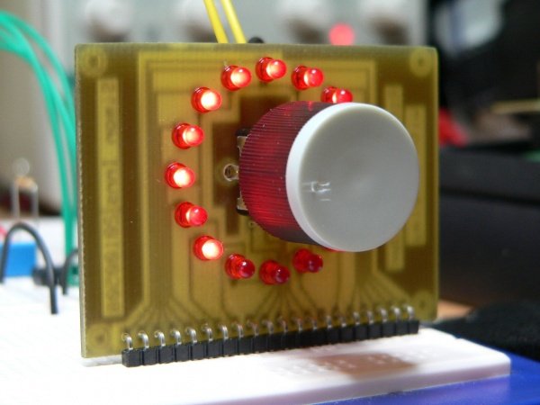
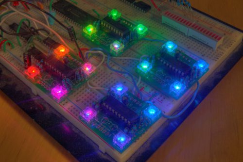
This pic sort of set the basic scene, and by printing out the board layout and pasting onto little pieces of paper I could start to visualise the final design. One thing obviously missing from this early design was a way to set the time…..so I thought,and thought.
Then I added SMD switches for input which can be seen in the intro picture.

Step 2

Programming and Micro selection

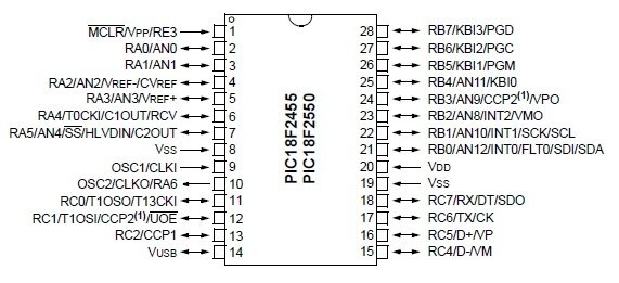
I am pretty familiar with programming and PIC 16F88 and had a few lying around from other projects. It seemed an obvious choice to save learning a new instruction set or new lot of onchip peripherals. This device has two ports A,B a selection of things like a serial i/f, A/D converter, a nice comfortable 8kb Flash rom and scads of memory…a whole 368 bytes of ram. One thing that was also handy was that it had pins for an onboard oscillator which could be connected to a common 32.768khz watch crystal for timekeeping and low power modes. The timekeeping oscillator can run even when the device was in low power mode. Lastly it could wake up when it detected a change on some of the pins (pins 4-7/portb have wake on change of state capability).

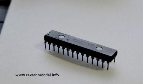
Because this was to be as small as possible I used a 20pin SOIP 16F88. This was a 300MIL wide version, Microchip have a 150mil SSOIP (skinny, small outline package), but considering the device was to be hand prototyped, I wanted to use a bigger easier to handle chip.

Obviously a SOIP package wont fit in a programmer so I had to use ICSP….which resulted in a whole lot of grief! ICSP is a way of programming the microcontroller, while it is still in a circuit. ICSP stands for In Circuit Serial Programming and is commonly used to program ‘blank’ boards, or update software without unsoldering/socketing the microcontroller.

Firstly I didn’t read enough about ICSP to add the right circuitry to handle ICSP in my first prototype. Then I didn’t read the microchip datasheet regarding a couple of extra pins on the 20pin 16F88SOIP. These pins are the AVss and AVdd pins. They normally provide the reference voltages for the A/D converter.

I took a while to figure out that these pins must be connected (I connected to GND/Vdd) for ICSP to work.

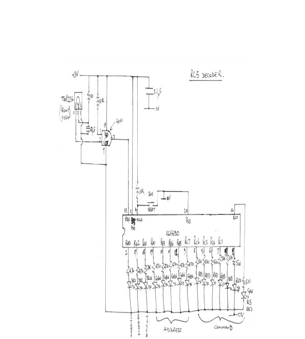
Also important is to have a proper reset circuit for the MCLR pin. This is very important so the ICSP program can reset the microcontroller, prior to doing its programming.

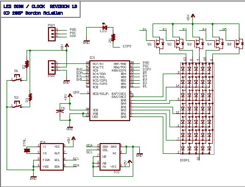
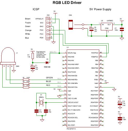
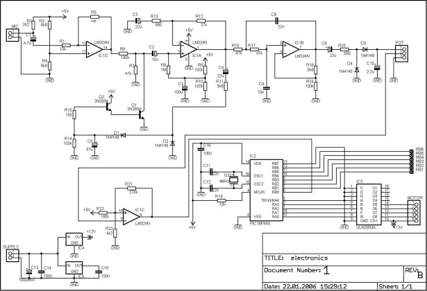
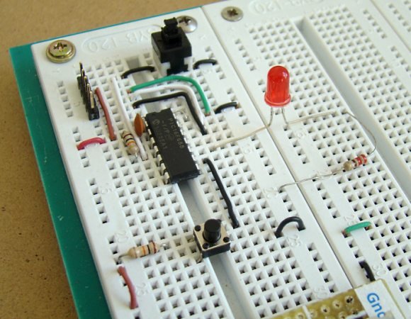
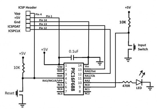
See the main picture in this section. It shows the MCLR pin connected to Vss via a pullup resistor and a diode. The pullup is necessary, because for ICSP to work you should really have the MCLR configured as a reset pin, rather than a input pin (more on this later). The diode prevents the Vpp voltage from the ICSP programmer which can be around 13V from damaging the rest of the circuit.
The picture also shows the connections for Vdd and AVdd connected together as for GND/AVss.

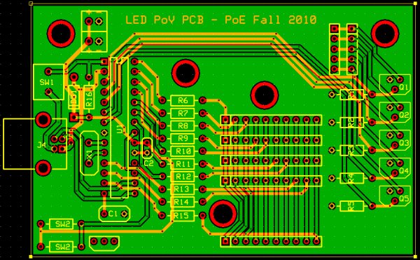
Refer to the Eagle schematic files for full schematic( or in the next section) but in the main picture note the little ‘X’ shaped symbols. These are SMD pads, there are no connectors in this device so SMD pads are used to solder power connections and the ICSP connection. The ICSP pins are arranged on the board in a convienient location. Short lengths of wire connect to a 10pin IDC header (pretty standard for ICSP programmers). The sub picture shows this arrangement.

They are also used to solder in the watch crystal. In the 16F88 the PGD and PGC pins are also the T1OSO and T1OSI pins which are used to connect an external crystal to the PIC T1 oscillator to make a real time clock. Fortunately you can also use these when programming via ICSP as well…..if you are careful.
If the oscillator is going when the ICSP programmer tries to use the pins, the ICSP programmer is going to have trouble. You need to add a delay at the start of your program. The code fragment below shows this in action. Note I’m also disabling the external oscillator as soon as possible after startup just for good measure :
void main()
{
unsigned char i;
unsigned short nDelay;
t1con = 0; //disable timer1 as soon as we reset
osccon = 0x76; //set for internal 8MHz clock
while( (osccon & 0x04)==0); //and wait for clock to settle and be ready

//setup peripherals
porta = 0;
portb = 0;
cmcon = 0x07; //disable comparator output, do now to set trisa properly
trisa = 0xff; //All set to input at startup
trisb = 0xff; //all pins in portb set to input
ansel = 0x00; //no analog in this cct….important step often forgotten, I did!!

delay_s(2); //allow programmer time to do stuff… VERY IMPORTANT

Lastly in the main picture note the symbol SMJ100 which is bridged in the upper top left hand corner called SJ100. This was to be used in an emergency if I accidentally programmed in a configuration that disabled the MCLR pin and couldn’t stop the watch oscillator stuffing up the ICSP PGD/PGC pins. This is another handly Eaglecad library part, a simple SMD link. By bridging it on my board it is a convienient place to unbridge if necessary. This would be necessary in the above situation. Normally you only connect the MCLR pin (to reset the chip), the GND pin (for reference) and the PGD/PGC pins to use ICSP. In practice the programmer will reset the chip, send magic control signals to the processor via PGD/PGC and get it to be receptive for some new data lovin’.
However if the processor is busy doing other things and is not going to respond to a reset, you need to yank it’s power rail to get it’s attention. In this case the Vdd pin of the ICSP programmer needs to be connected to the circuit. I would cut the bridge, connect a wire to the Vdd SMD pad (the little ‘X’ symbol nearby) and give the processor new instructions. In the end when I downloaded dodgy code, I just powered up the cct from the programmer without using this system. If you had a more complex or power hungry circuit you should have some way of disconnecting the processor from the circuit power rail and connect it to the Vdd pin on your programmer.

So in summary to do successful ICSP remember:
– setup a proper reset circuit with protection diode and pullup resistor
– connect AVdd/AVss to the power rails if you are not using them (and the chip has them, only for 20pin 16F88…not for other versions).
– in your layout, put the ICSP connections somewhere sensible and easy to get at.
– have a way of isolating the processor power from the cct power and connecting ICSP Vdd for emergencies
– avoid emergencies by ensuring that the PGD/PGC pins are ready for use as soon as possible after a reset.

Step 3

Some circuit Problems

wrist watch LED pattern timepiece schematics

The main image below shows the circuit used in the intro picture. It has a few omissions that I think should be noted for anyone attempting to make a simliar cct.
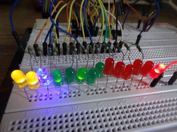
Apart from the ICSP and processor which we’ve seen, we now see the charliegrid which will discussed next section. This is the LEDs and limiting resistors in the top right hand corner.
At the bottom left hand corner we see the three microswitches.
Note that the switches just connect three pins on port B to ground.This was a problem.

I had originally intended to use the weak pullup function on Port B of the 16F88 to save some components, notably pullup resistors on the switch inputs. However when laying out the board I assigned one of the charliegrid control lines to another pin on PortB. This was a simple layout decision, it was easier to layout the board in such a small space by moving the traces to more easily accessible pins on the PCB. If you have enough space you’d connected all of the charliegrid controls lines to the same port.

However when the charliegrid program was written, it worked OK, except for some sort of leakage on LEDs connected to the PortB pin. When one LED was lit up, a couple of other ones lit up weakly. In the end I added pullups to the switches and disabled the weak pullups. You can see the extra added pull up resistors and some prototyping mistake wire in the ICSP picture of the previous section.

Another problem was a silly one, made by me cutting and pasting code from another project to the microdot project without thinking.

I had inadvertantly copied code that enabled the A/D converter for one of the pins. This is a big problem if you then use that pin as an output. It draws too much current and eventually will kill or seriously damage the pin. This is exactly what happened, everything ran OK at first, and after testing overnight I found some LEDs were not lighting at all, and some were lighting several LEDs at once. This took several nights to track down to a faulty RA0 pin….the one I had accidentally configured as an analog input. The charliegrid multiplexing system necessarily configures it’s control pins as either input or output.

I replaced the chip, very carefully making sure not to lift the fine tracks in the process and now make sure I disable all analog inputs, which can be seen in the previous sections code fragment.

Last problem was with the power supply. I’ve used a simple dropping diode to drop the 6V to 5.4V from two button cells, this saved frying the micro everytime you changed batteries. Not the best way to regulate the voltage, but it is very space saving.
The problem came about because I only had a 16F88 device handy, not a 16LF88 device. The ‘LF’ allows operation down to about 3V, so the battery could drop to nearly half power before the device would stop operating. With the ‘F’ device, the battery pair can only drop about 1V before the device will start resetting itself because the power is too low.
I’d also planned to get the watch to put itself into low power mode, and wake up when a button is pressed to conserve power. The software at the moment doesn’t have this functionality, it will be added when the housing and mounting instructable is written.

So for this section:
– you can’t use weak pullups on an charliegrid control signals
– be careful not to configure a charliegrid control signal as an analog input as well
– use a 16LF88 device instead of a 16F88 device so you can get better life from the battery.

Step 4

The Charliegrid…layout and programming

The previous section introduced the ‘charliegrid’.

For those not familiar with this, it is a way of controlling lots of LEDs with only a few pins by taking advantage of the tri-state nature of a microcontrollers pins and the forward voltage of the LEDs. There are numerous explanations of the charliegrid and their applications on the net so I won’t give more than a quick explanation.

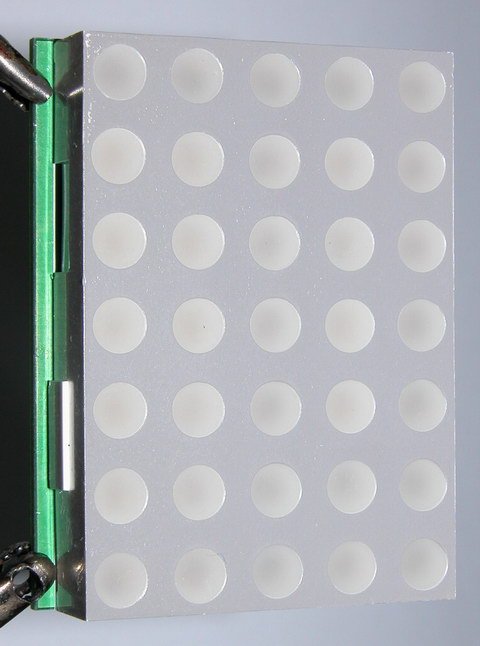
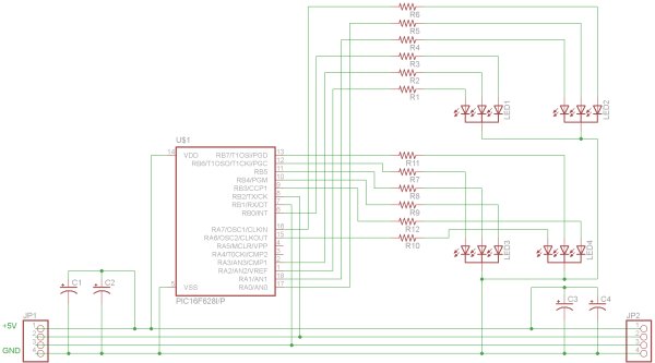
Note the configuration of LEDs on the charliegrid.

You can put a +ve voltage on one control line, and you can put a 0V on another line. You leave the other control lines unconnected to anything. Imagine having the charligrid on a breadboard and you connect two control lines to a battery. In the case of the microcontroller, you program these two pins to be outputs, and set one pin to a logic ‘1’ and the other to a logic ‘0’.

You leave the other control lines unconnected, or in the case of a micrcontroller you set these pins as inputs.

The LED with the most direct connection to this connection will light up. Even though there are multiple paths through these pins through other LEDs, only one will light because when it does, the forward voltage of that LED will always be lower than any combination of other LEDs.

When the position of the logic ‘1’ and ‘0’ are reversed, and the same control lines are selected, the LED in the reverse position lights up. You can see these in the circuit diagram as pairs of LEDs between every combination of control inputs. As such 6 control lines can operate 30 LEDs individually….not at the same time of course!

To light up an LED it is simply a matter to program the microcontroller to send a logic ‘1’ or a logic ‘0’ to which ever two control lines corresponded to that LED and set the others to inputs.

By briefly illuminating each desired LED in turn, you can build a display like a monitor due to persistance of vision effect. Because only one LED can be lit at a time, this is always necessary in a charliegrid.

In the code the porta/portb output registers and tris registers are loaded with values pre-calculated to light up an LED. Took a while to calculate them all. Here is a fragment:
// LED1 LED2 LED3 LED4
unsigned char LEDS_TRISA [31] = { 0xfd, 0xee, 0xf7, 0xfd,
unsigned char LEDS_PORTA [31] = { 0x02, 0x01, 0x08, 0x00, 0
unsigned char LEDS_TRISB [31] = { 0xfb, 0xff, 0xfb, 0xfb, 0
unsigned char LEDS_PORTB [31] = { 0x00, 0x00, 0x00, 0x04, 0x
If anyone knows of a generalised charliegrid algorithm, I’ll be very interested.

But first the grid had to be layed out. For the microdot this was a big challenge because of the lack of space. The main picture shows how this became managable.

Initially I put the LEDs in pairs in the grid and the bottom components in as well where I wanted them. This was very confusing when trying to sort out the best most efficient connectivity of the complex charliegrid. By moving the LEDs away from the bottom components, the ratsnest became easier to read. After that it was simple to move the grid back onto the bottom side components and do the bottom layout with a minimum of layer to layer vias and crossover tracks. You can see the impact of moving and rotating the LEDs to get the best arrangement in the crazy naming sequence of the charliegrid schematic after renumbering LEDs on the board.

For more detail: Microdot – wrist watch LED pattern timepiece using PIC16F8 microcontroller

Current Project / Post can also be found using:

  • Microcontroller led light project

The post Microdot – wrist watch LED pattern timepiece using PIC16F8 microcontroller appeared first on PIC Microcontroller.


A complete guide for LED Blinking

$
0
0

What is LED?

A light-emitting diode (LED) is a semiconductor light source. LEDs have allowed new text, video displays, and sensors to be developed, while their high switching rates are also useful in advanced communications technology.

What is LED Blinking?

LED blinking is same as eye blinking. Close and open eyes is called an eye blink in same manner on-off-on (or off-on-off)transition of an led is an LED blink. If such process is done repeatedly it is said LED Blinking.A complete guide for LED Blinking

Why to do LED Blinking?

LED blinking is considered as the first project to learn any microcontroller interfacing. It is considered as “Hello world” for embedded system.
LED blinking is also useful to make some indications (Slow blinking may be for normal operation and fast blinking may be used for a malfunction or faulty condition).
You can use LED for debugging your embedded applications.
In optical fiber and Infrared Communications LEDs are used as transmitter.

How to do LED blinking?

Here is a quick review about how you can do LED blinking.

LED Blinking Circuits

LED blinking with One transistor

LED blinking with one transistor

LED blinking with Two transistors

LED blinking with two transistors.Here Two LEDs will blink vice versa. When one is on the other is off.

LED blinking with AC mains voltage

LED blinking with AC (mains) voltage

LED blinking circuit to blink led at Line voltage

LED Blinking with Solar Power (Infinity Blinker)

We have seen this circuit earlier. This circuit don’t need any power source other than Solar power and as of now it is still working from last 5 years.

LED blinking circuit with solar power

LED blinker with solar power

LED Blinking with LM3909 IC

LED blinking with LM3909 IC

LED Blinking with 555 timer IC

LED Blinking with 55 timer ic

to calculate timer time period have a look at 555 timer frequency calculator.

LED Blinking with Op-Amp

LED blinking circuit with Op-amp

LEDs that blink by themselves

Till now we have seen normal LEDs that behave normally so we need external circuit to make them blink, but here is an LED that Blinks  by itself you just have to apply DC voltages. Within the supply voltage range, no series resistor is required. These LEDs have a built-in blinking IC and have a blinking frequency from 3Hz to 1.5Hz.A complete guide for LED Blinking schematich

How to connect LED with Microcontroller?

To connect LED with Microcontroller you have to put current limiting resistor, you can use this online LED Resistor calculator tool or you can use this awesome dial.  You can connect LED either in sink or source configuration.They are shown below.
Sink Or Source Logic Selection


For more detail: A complete guide for LED Blinking

The post A complete guide for LED Blinking appeared first on PIC Microcontroller.

Lab 2: Basic digital input and output

$
0
0

Description

Today we will learn how to read digital inputs from a push button switch. A digital input has only two values: 1 and 0. The configuration of the push button switch is same as that of the reset switch except it goes to a different port pin. The status of the switch will be read through RC1 and every time when it is pressed, an LED connected to RC0 will be toggled ON and OFF.Lab 2 Basic digital input and output

Required Theory

You must be familiar with the digital I/O ports of PIC16F688 and their direction settings. If you are not, read Digital I/O Ports in PIC16F688.

Circuit Diagram

To our last setup (see Lab 1: Flashing an LED), connect a push button switch to RC1 as shown below. The input ports of a PIC microcontroller have very high input impedance, and therefore, during normal condition when the switch is open, the RC1 pin is pulled ‘High’ through the external 10K resistor. When the switch is pressed, RC1 is pulled to ground and the microcontroller will read it as logic ‘Low’. In this way, a simple push button switch with a pull-up resistor can be used to provide digital inputs (1 and 0) to the microcontroller.

Software

Since the switch is connected to RC1, this port pin must be defined as input. This is done by setting the corresponding bit in the TRISC register. Again, don’t forget to disable the comparators and ADC channels. The code for this experiment is provided below. You should compile it with the MikroC compiler and load the output hex file inside the PICMicro. The MikroC compiler has an in-built library routine (named Button) for reading digital inputs from push button switches. The syntax is,

You can see that the Button command has debounce features built in. – See more at: Lab 2 Basic digital input and output schematich

Debouncing a switchWhen a mechanical switch (like a push button) is pressed or released to make or break an electrical contact, the switch tends to make multiple transitions between ‘open’ and ‘close’ before coming to the stable final state. This is called switch bounce and this activity may go on for tens of milliseconds. We cannot see this bouncing but a microcontroller is relatively fast as compared to the action of the switch, and is, therefore, able to recognize this as multiple button presses and respond accordingly. Therefore, the switch must be debounced before it’s status is read by a microcontroller. Debouncing circuits require extra hardware and thus raises the cost of the embedded system. The easiest solution is to implement debouncing in software. The simplest logic is to wait for a few milliseconds (5-20 ms) after the key press or release is detected, and read the final state of the switch again to make sure it is a valid button press or release.


For more detail: Lab 2: Basic digital input and output

Current Project / Post can also be found using:

  • MicrochipEngineer AuthoratPICMicrocontroller

The post Lab 2: Basic digital input and output appeared first on PIC Microcontroller.

martin lightjockey 2 free

$
0
0

The new Martin Light Jockey II Lighting Software Kit is a new way to control your. LightJockey Manager is a free-of-charge software add-on for our LightJockey Page 2 the interface. In control panel, the USB interface is recognized as USB. A: I did test the Martin LightJockey, but this software doesnt support the interface. Free version of your software-Music Visualization for private non-commercial Martin Light Jockey Universal USBDMX Interface on Recordcase. De Online-Shop. VAT Free Delivery Germany. 2 XLR Adapter, 5 pin male 5 pin male If you see any USB-DMX512 Dongle can support lightjockeyAvolites martin lightjockey 2 free

Pearl2004titanD4grandMA. Martin Lightjockey Free Daslight. SunLite Suite 2 Free martin lightjockey 2 free Martin Light Jockey 2 USB 1024CH is now available at LAMBA and ready for. LightJockey Manager is a free-of-charge software add-on for our LightJockey Light jockey from martin has a offline visualisator in the free software. The massive light rig we programed from our office got power 2 hours LightJockey 2. 0 software includes audio CD-ROM capability as well. Windows 9598ME2000XP; free slot or port for DMX interface hardware; 20 MB hard Apr 22, 2008. MARTIN LightJockey Windows-based controller. Universal USBDMX Interface with 2 x 512 Channels DMXINOut; Control of up to 100 Jul 11, 2011. GDS Sound and Light LightJockey II 90702070-LightJockey 2 is a flexible, Martin USB Duo DMX interface with 2 x 512 Channels DMXINOut; Control of up. Add-on LightJockey Manager, free downloadable software for Martin LightJockey Universal USB DMX dongle Jockey in Sound Vision, USB to DMX Interface II for Martin Light. This is for a Martin Universal USB dongle for the free Martins free LightJockey software, tested working this morning Martin LIGHTJOCKEY 2 DMX Lighting Controller Software for sale at Planet DJ. Guaranteed lowest prices and free shipping on most dj equipment. Authorized View Martin LightJockeys business profile and see work history, affiliations. Free Trial People. Companies. Need more. Try our Advanced Search 20 criteria. LightJockey 2 is a flexible, easy-to-use Windows-based controller utilizing a Direct-Download: Martin LightJockey 2 95. 1; Total size: 81. 00M Click to see file details. Health: 1 seeders 0 leechers; File Format: RAR; Indexed time: 2 Video Free Martin Light Jockey Tutorials Assistente. Martin Lightjockey Tutorial-Set up multiple tabs Club:. Light Jockey 2 USBDMX Interface-Martin: Postage free within Germany. Martin Lightjockey-2 Interface. Untersttzt MP3, Audio-CD, SMPTE und MIDI Timecode; Martin USB Duo DMX interface mit 2 x LightJockey 2 Specifications Description. LightJockey 2 is a PC based DMX lighting-control-system consisting of a software. Fixture profiles for non-Martin fixtures more than 100. Free slot or port for DMX interface hardware. 20 MB hard LightJockey 2 is a flexible easy-to-use Windows-based controller utilizing a USB to. Add-on LightJockey Manager, free downloadable software for scheduling Aug 28, 2003. Denmark-Martin Professional has introduced Fingers, a handy hardware interface for its popular software-based LightJockey controller.martin lightjockey 2 free schematich Of individual or multiple sequences and latching of specific cuessequences. LSi Magazine, but you can search and read the digital edition of our magazine for free

Mar 4, 2011. LightJockey 2 is a flexible, easy-to-use Windows-based controller utilizing a USB to DMX Interface. One of the industrys most popular Martin Light Jockey 2 USB Controller-The LightJockey package contains. Add-on LightJockey Manager, free downloadable software for scheduling events.


For more detail: martin lightjockey 2 free

The post martin lightjockey 2 free appeared first on PIC Microcontroller.

Solar Tracking System

$
0
0

This is a simple PIC microcontroller based Solar Tracking system, only basic electronics skills are required. It uses 2 unipolar stepper motors and 4 IR-850nm LEDs as sensors to follow the sun  maximizing solar panel illumination.Solar Tracking System

The entire prototype frame was built from simple, cheap and widely available strip board. Just cut it to a required size, widen the holes with screwdriver to fit connecting bolts and you’re done. If you want to build a similar circuits or use current configurations as a basis for more advanced design follow the pictures, hopefully it will give you some ideas. Here are some of the development steps taken from a standard strip board to a final design.

The assembly code is a modified version of original code from recently published Stepper Motor Interface PIC16F post. Now 2 step motors can independently rotate to any direction according to amount of light received by each IR LED. For example if Upper LED receives more light than the Lower LED PIC microcontroller will move the platform with mounted solar panel in the direction of stronger light source. Motor control is done by outputting coil switching sequence through ULN2003A.During the development a few limitations or “bugs” of current design were discovered. Although the payload platform can move in 2 Solar Tracking System schematichaxis,(UP,Down,Left,Right) the solar cell attached to it is too heavy for stepping motor that was used to rotate it,if I had to build a new solar tracker  I would change the center of mass or use counterweights for better balancing thus reducing the motor load, also direct frame connection to a platform rotating motor without some sort of reducer mechanism was a mistake, again the final design with solar cell attached weights too much and the motor doesn’t have enough torque to rotate it properly even with max allowed 24 V.UP/Down axis movements are working OK.Assembly/hex files available here.


For more detail: Solar Tracking System

The post Solar Tracking System appeared first on PIC Microcontroller.

LED Sign has a purpose! using pic microcontroller

$
0
0

The single character LED sign I had been playing with now has a purpose! Shortly after discarding several ideas of having it as a serial display for PC/Server status, or hooking it up to the internet and a webcam, I came up with an actual useful purpose. The sign can be a clock! I have two ‘modes’ planned; traditional numbers and binary. All geeks love binary clocks, but most of us are lazy and would rather read regular ‘ol numbers.

 LED Sign has a purpose!To facilitate the role as an clock, I had to redesign the circuit quite a bit. Two new ICs were added, allowing the LED Sign to keep time, and providing some much needed storage.

The first of the new ICs is a Real Time Clock. Because I’m cheap, I chose the M41T80 from ST Micro. It’s an inexpensive clock, similar to the Dallas DS1307 but lacking a few minor features. First, the clock has no power-on reset detection. It just starts up as soon as power is supplied. The Dall 1307 has a stop bit which gets set if the clock experiences a POR, so the firmware can test if the clock needs to be initialized or not. The T80 datasheet mentions some registers may get set to default values on power up, so I’ll have to read it a few more times to see if there is a way I can check for a POR. Second, the T80 has no support for a separate backup battery. Instead, ST recommends you place a diode in series with the clock, and use a large capacitor to provide backup power. Last, there is no automatic leap year / leap second correction, oh well!

 LED Sign has a purpose!The second IC is a 16 kilobit serial eeprom, similar to the Microchip 24C16, I chose one from Catalyst semiconductor due to lower costs. The eeprom is arranged as eight banks of 256 bytes each. The chip contains a 16 byte write-buffer, I’m not sure if it can cross a bank boundary or not, I’ll program my firmware assuming it can not. The eeprom will be storing character strings related to operation of the LED Sign as a clock, as well as user programmed messages and possibly simple graphics.

I’ve also added some micro switches for adjusting the clock and changing settings, also a 32.768kHz crystal was added to providing the timing source for the RTC.


For more detail:  LED Sign has a purpose!

The post LED Sign has a purpose! using pic microcontroller appeared first on PIC Microcontroller.

Infra red remote control tester for Philips RC5 protocol

$
0
0

Philips invented the RC5 protocol for controlling electronic equipment such as CD players, VCR’s and audio amplifiers way back in the 1980’s. The RC5 standard has been adopted and used with great success ever since, which means it is probably the most common IR remote control format in your home today. We have recently been playing around with a PIC microcontroller based RC5 decoder programmed in C, with the purpose of testing any RC5 based remote handset you may have. The image above shows the RC5 code for a button press of ‘1’ on the CD player remote control decoded into binary and displayed on the 14 LEDS – the address data for a CD player is ’20’ hence the 10100 binary pattern on the green LEDS. The RC5 command for ‘1’ is unsurprisingly 000001 in binary as shown on the red LEDS. The two start bit LEDS (yellow) are showing 11 binary and the toggle bit is off. In the pic below the ‘1’ button has been pressed again showing the toggle bit now being set (blue LED).Infra red remote control tester for Philips RC5 protocol

The RC5 protocol is based upon a 14 bit serial code (binary 0/1) – when a key is pressed on the remote, the following bits are emitted:-
bit 1 (start bit) S1
bit 2 (second start bit) S2
bit 3 (Toggle bit) T
bits 4 – 8 (5 device address bits) A4 A3 A2 A1 A0
bits 9 – 14 (6 command bits) C5 C4 C3 C2 C1 C0

Below is a diagram showing the 14 bit pattern and the pulse and space timings for a typical RC5 transmission. More information on RC5 including device address codes and commands can be found at the link below.
RC5 protocol

The data is encoded using Manchester or bi-phase encoding of the binary data, in order to maximise noise immunity. A logic ‘1’ is represented by a low half bit followed by a high half bit, whilst a logic ‘0’ is represented by the opposite pattern i.e a high half bit followed by a low half bit. The transition from high to low or low to high always occurs at the mid-bit point. The bit length is approximately 1778us, so the mid bit point is at 889us – in other words, each half bit is 889us long. Manchester encoded data can be decoded in one of two ways. The first method is to detect the direction of change at the mid-bit point (low to high or high to low). A high to low transition at the mid-bit point indicates a logic ‘0’ whilst a low to high transition indicates a logic ‘1’. The second method involves simply reading the logic level present in the second half of the bit period, which is the method I used for this project.

The RC5 decoding algorithm employed is written in C and is targeted at a PIC 16f690 microcontroller. A 36kHz IR receiver IC is used ( TSOP2236 but I also had good results from an old IS1U60L I had lying around) which removes the 36kHz carrier frequency from the transmitted RC5 code, leaving a binary bit stream which can be fed to the microcontroller. As the IR receivers have an active low output, I passed it’s output through a inverter (NOT) logic gate – this can also be achieved in software by reversing the logic of the code if desired. The algorithm works by first detecting the rising edge of start bit S1. S1 is not decoded as we can’t tell what happened before that first rising edge – all we know is that S1 is always logic ‘1’ so we set it to a constant ‘1’ in software. After that we get a second interrupt on change (IOC) which indicates the start of S2, which we do want to decode.The negative edge detection triggers the IOC routine again where the logic level present on RB4 (IOC input pin) is sampled after a delay of 1334us (889us x 1.5) to ensure we are 3/4 of the way though the whole bit, thereby sampling the logic level present in the second half of the bit period. In the main loop we have set up a one dimensional array of 14 elements to store the RC5 bits sequentially, incremented by index variable j. The RC5 bit pattern is then output on PORT’s A, B and C to 14 LED’s, so that the correct operation of the remote can be observed. For the prototype I made the S1 S2 bits yellow, T bit (toggle bit) blue, the device address bits green, and the command bits red. A further green LED is connected to PORTCbits.RC0 to indicate the receiving of RC5 data.
Here is the schematic – note that if you use a different IR receiver check the pin out details – they are not all the same!

RC5_schematic
One issue to be aware of is ambient light affecting the IR receiver – I found that I had to shield the receiver from ambient light using a cloth to prevent false decoding codes. Have fun !
Here is the software listing which was compiled using XC8.

/*
* File: rc5_IOC.c
* Author: Phil Glazzard
*
* Created on 07 August 2015, 20:30
*/

// PIC 16f690 Configuration bit settings
#include xc.h

// #pragma config statements should precede project file includes.
// Use project enums instead of #define for ON and OFF.Infra red remote control tester for Philips RC5 protocol schematich

// CONFIG
#pragma config FOSC = INTRCIO // Oscillator Selection bits (INTOSCIO oscillator: I/O function on RA4/OSC2/CLKOUT pin, I/O function on RA5/OSC1/CLKIN)
#pragma config WDTE = OFF // Watchdog Timer Enable bit (WDT disabled and can be enabled by SWDTEN bit of the WDTCON register)
#pragma config PWRTE = OFF // Power-up Timer Enable bit (PWRT disabled)
#pragma config MCLRE = ON // MCLR Pin Function Select bit (MCLR pin function is MCLR)
#pragma config CP = OFF // Code Protection bit (Program memory code protection is disabled)
#pragma config CPD = OFF // Data Code Protection bit (Data memory code protection is disabled)
#pragma config BOREN = OFF // Brown-out Reset Selection bits (BOR disabled)
#pragma config IESO = OFF // Internal External Switchover bit (Internal External Switchover mode is disabled)


For more detail: Infra red remote control tester for Philips RC5 protocol

The post Infra red remote control tester for Philips RC5 protocol appeared first on PIC Microcontroller.

MRNet — Wired Cab Module (Revision A) using pic microcontroller

$
0
0

Table of Contents

 MRNet -- Wired Cab Module (Revision A)

 Introduction

{Introduction goes here.}

Cab Design Goals

The goals for the handheld cab are:

  • Light weight.
  • Comfortable.
  • Not visibly warm (i.e. low power consumption).
  • Assembled from readily available parts, including box.
  • Customizable control labels.
  • No surface mount chips.

The feature set I decided on for this handheld cab is:

  • Up to two 4 digit 7-segment LED displays.
  • Up to 16 LED’s.
  • Up to 8 buttons.
  • Up to 4 analog inputs via linear potentiometers.

 Cab Electronics

The handheld cab schematics are broken into several pages. The schematics are:

Power And Cable Interface

The first schematic shows the power and cable interface electronics:

This circuit starts with the power and ground coming on the PWR1 and GND pins of N1 and being routed through SW1 into voltage regulator VR1 with capacitors C1 and C2 to provided regulated 5 volts for the rest of the handheld cab. In addition, D5 and R94 provide a current limited supply to charge the 9-volt Nickel Cadnium battery. The 9-volt battery is chosen because it is lighter than 4 or 5 AA batteries. If the power from PWR1 and GND2 ever goes away, diode D6 will kick in and supply voltage and current for VR1 and its two capacitors C1 and C2. The concept is that the Nickel Cadnium battery is always being charged when the cab is plugged into the cab station and the battery is discharging only when the operator is moving between cabs. The on/off switch is after the battery so that the cab can be charged overnight without having to leave the rest of the electronics on. Going back to connector N1, the signal comes in on the SIG pin of N1 and is fed into the Schmidt triggerU19A and the resulting signal is fed into the UART input pin of the microcontroller. The UART output pin of the microcontroller is fed into the open collector NAND gate U19A which is pulled up by resistor R95 and the resulting output signal is sent out on the SIG pin of R95.

 MRNet -- Wired Cab Module (Revision A)

Microcontroller

The handheld cab is organized around a Microchip PIC16C73 in an 28-pin SDIP package. The PIC16C73 has a 5 channel analog to digital converter, a built in asynchronous serial port, and enough I/O pins to control the rest of the handheld cab.

Given that there are a total of 64 LED segments in the seven-segment displays, 24 indvidually controllable LED’s, and 8 button inputs, there is no way to directly connect each LED and switch to an individual pin on the PIC. Instead, I have arranged all of the input and output data as one big shift register using `164 and `165 shift registers. This is basically just a simplistic I2C bus. The code to shift 8-bits of data out looks like it will take around 32 instructions. This routine will need to be called about 12 times (12 x 32 = 384,) so an update will not be visible to the operator.

The I/O lines on the PIC are labled below:


For more detail: MRNet — Wired Cab Module (Revision A)

Current Project / Post can also be found using:

  • digital potentiometer on Proteus with microcontroller
  • japanese big tits watch
  • microcontroller led projects

The post MRNet — Wired Cab Module (Revision A) using pic microcontroller appeared first on PIC Microcontroller.


Electronic Quiz Buzzer Circuit Diagram using PIC Microcontroller

$
0
0

Usually high level quiz competitions are very much time-oriented as it becomes significant to determine who has answered first. So here we’ll see how to make a buzzer system that helps to decide the winners.

Actually I designed this circuit of buzzer for quiz program conducted in our area and then I thought it may help someone, so I decided to introduce it here.Electronic Quiz Buzzer Circuit Diagram using PIC Microcontroller

This game show buzzer circuit uses PIC16F877A and a LED matrix to display who has pressed the button first. As soon as someone hits the button first, all other buttons are disabled helping to find the person or group which are ready to answer the question.

Read:LED Interfacing with PIC Microcontroller: Embedded C program with circuit

A reset button provided for the quiz master enables all the switches again for the next question. The led matrix helps to display the number in larger size and it’s designed to blink continuously. Buzzer will be ON for a second when anyone presses the button.

Components required

  1. PIC16F877A
  2. LED matrix 8×8
  3. Transistor BC548
  4. Resistor (1K,10Kx7,220)
  5. Capacitor(33pfx2)
  6. Crystal (12 MHz)
  7. LED Green
  8. Buzzer 5V(PCB Type)
  9. Push button x7

Quiz buzzer schematic working

  • LED matrix is connected through PORTB and PORTD of the microcontroller; cathode row is connected to PORTB and anode row is connected to PORTD.
  • When the power is ON, green LED starts to glow indicating that all switches are ready to press and LED matrix in blanked by sending PORTD=11111111 AND PORTB=00000000.
  • PIC microchip will continually scan the pins of PORTC to check if someone presses the button. It will check the next button only if the present button is not pressed.
  • While programming I had chosen the ‘if’ statement so as to avoid activation of two buttons at the same time by checking each pin from 0 to 7 of PORTC. Probability of this occurring is very low (And I know it’s a little bit unfair if that happens). The use of ‘case’ statements will check all the pins at the same time which may lead to activation of two buttons at a time.

Note:  You may also want to check out if-else statements in C programming.

  • The pins of PORTC is connected to +5V (pull up) through a 10K resistor, so if no one pressed the button PORTC gets 11111111 as default.
  • Pressing of any switch will make a short circuit to ground getting a logic zero at the corresponding pin of PORTC and so the program execution will enter into the sub function (loop) of the particular group number to display on the LED matrix.
  • Here I interfaced LED matrix directly to the PIC micro controller which makes the circuit simpler.
  • When the program execution enters in to any particular sub function(loop), it will enable the buzzer by sending a logic 1 to the 5th pin of PORTC and it send a logic 0 after 1 second (make beep sound of one second long).
  • Then enters in to the matrix loop, which scans each column with delay of 3 milli second.
  • PORTB sends the data corresponding to the column; higher scanning speed will make see the display as a number due to the persistence of vision of the eye.
  • Upon pressing the reset button, program execution will return to the main program.

Electronic Quiz Buzzer Circuit Diagram using PIC Microcontroller schematichQuiz buzzer program

The microcontroller code for this project is available at our Program Center.

I hope you like this quiz buzzer circuit diagram and let me know through the comment box below if you need any further assistance.


For more detail: Electronic Quiz Buzzer Circuit Diagram using PIC Microcontroller

The post Electronic Quiz Buzzer Circuit Diagram using PIC Microcontroller appeared first on PIC Microcontroller.

Circuit-Zone.com – Electronic Projects

$
0
0
Rotary encoders are very versatile input devices for microcontroller projects. They are like potentiometers expect of digital nature and unlike analogue potentiometers they never wear down. Circuit-Zone.com - Electronic ProjectsRotary encoders not only provide 360 degrees of rotational freedom they also allow digital positioning information to be gained without the use of analogue to digital converters (ADCs). When using rotational encoders in projects it’s possible to use the same encoder to represent a number of different input types, however this requires some form of feedback display to let the user know what information he is inputting and the ‘position’ of the encoder. The project is based around a 24 position rotary encoder, 16 LEDs arranged in a circle around the encoder, an A6276 16 LED serial driver IC and the PIC182550 microcontroller. A rotary encoder has 3 pins usually called A, B and C. The C pin (which is normally the centre pin) should be grounded and both A and B should be connected to the microcontroller with individual pull-up resistors on each input. In this project I used RB4 and RB5 on the PIC to connect the encoder; this has 2 advantages, firstly you can use the PORTB internal weak pull-up (which means you do not need external resistors) and also the PIC provides an ‘interrupt-on-change’ which can be used to monitor the encoder.Circuit-Zone.com - Electronic Projects schematich

Build Accurate LC Meter and start making your own coils and inductors. This LC Meter allows to measure incredibly small inductances making it perfect tool for making all types of RF coils. LC Meter can measure inductances starting from 10nH – 1000nH, 1uH – 1000uH, 1mH – 100mH and capacitances from 0.1pF up to 900nF. The circuit includes an auto ranging and reset function to make sure the readings are as accurate as possible …


For more detail: Circuit-Zone.com – Electronic Projects

The post Circuit-Zone.com – Electronic Projects appeared first on PIC Microcontroller.

Circuit-Zone.com – Electronic Projects

$
0
0
For a long time I needed a good programmer pussy, even if it is programming, so from time to time the application gets where it is used. So I decided to build the programmer. I chose between a couple of projects from different authors, but eventually won PICkit2. Microchip released the schema directly in the user manual for the programmer.Circuit-Zone.com Electronic Projects On the Internet there are multiple versions of the programmer, it’s usually cropped version of the log analyzer features, UART terminal, etc., 12V inverter is a modified version of it and control the MOSFETs, unlike bipolar transistors used in the original design. And it also showed that becomes due to the switching inductance feta leave. Finally, I chose to use the original scheme, although it is quite complicated and the parts used in our country can not normally buy, but my problems with finding parts easily solved. I bought a transistor, the 16F2550 PIC and a few other things, resistors and fry the rest I bought from “us”. The price is pretty high, unfortunately, moving it around and 600CZK, the main prize and two processor makes the EEPROM. Below we describe the involvement and put into operation.Circuit-Zone.com Electronic Projects schematich

Build Accurate LC Meter and start making your own coils and inductors. This LC Meter allows to measure incredibly small inductances making it perfect tool for making all types of RF coils. LC Meter can measure inductances starting from 10nH – 1000nH, 1uH – 1000uH, 1mH – 100mH and capacitances from 0.1pF up to 900nF. The circuit includes an auto ranging and reset function to make sure the readings are as accurate as possible …


For more detail: Circuit-Zone.com – Electronic Projects

Current Project / Post can also be found using:

  • led pics

The post Circuit-Zone.com – Electronic Projects appeared first on PIC Microcontroller.

10 tricks for interfacing to the PIC16C508

$
0
0

Most of the ideas in this chapter can be found on the pages of this website, but just in case you want to go over the capabilities of the ‘508A, we have brought them together.

Quite often when you are programming, the first thing you will run out of is output lines. Many projects need lots of drive lines and if you need more than about 8, you should go to another micro-controller.

Don’t expect an 8-pin chip to perform the impossible.

The designers of the ‘508A have done an amazing job providing 5 output lines (and one input line) in an 8-pin chip, but even so, many projects run out of drive-lines.

On other pages of this course we have shown how to expand the drive lines with a binary counter or shift register. This can increase the lines to more than 10 however if you want to add just one or two more devices than the chip is directly capable of handling (5), there are clever ways to connect them to the chip.10 tricks for interfacing to the PIC16C508

1. LED AND PIEZO ON ONE LINE

One of the simplest combinations is a LED and Piezo on a single drive-line as shown in fig: 1. These can be combined because the requirements of a LED are different to a piezo. A LED requires a constant HIGH for it to illuminate while a piezo requires a HIGH-LOW-HIGH waveform at approx 3kHz to produce a tone.

If the mark-space ratio of this waveform is kept short as shown in fig: 2, the LED will only illuminate very dimly. A short mark-space ratio means the “mark” is very small compared to the “space”. A very short on-time (mark) and a long off-time (space) will not affect the tone from the piezo but will deliver very little energy to the LED and this is exactly what we want.

On the other hand, each time the LED is activated, only a very small click will be heard, and this will hardly be noticeable. In this way the two devices can be combined on the same line.

2. LED AND PUSH BUTTON ON ONE LINE

In this book, we show how to connect two and up to five or more push buttons on a single input line and generally you will not have any problems adding buttons to a project. But if you want to add a secret reset button (or a “cheat” button, for example), it can be added across an existing LED as shown in fig: 3.

The resistor between the switch and micro acts as a safety resistor to prevent the output of the chip being damaged if the switch is pressed when the LED is activated, and it also acts as a dropper resistor for the LED.

These two items will work in combination because the impedance of the LED is very high when no voltage is across it and when the micro turns the line into an input line, it sees the LED as a high impedance. In other words it is not detected so that when the switch is pressed the micro only sees the switch as a LOW.

3. DIFFERENT PROGRAMS IN THE CHIP

Up to 5 different programs can be burnt into a single ‘508A and the required program can be accessed by soldering a resistor between one of the outputs and the “input-only” line – GP3, as shown in fig: 4.

During turn-on, a special program will put a HIGH on each output in turn and the output containing the resistor will determine the program.

Combining 5 programs in one chip will reduce inventory costs as the required program can be selected by fitting the resistor in the appropriate place on the board.

4. LINE REVERSAL

If a device is connected between two output lines as shown in fig: 5, a program can be written so that the device sees a voltage reversal. When one output is HIGH the other is LOW and this is then reversed.

The drive lines have a maximum output current of 25mA and this is enough to drive a number of different devices. If a red LED is connected in one direction and a green LED in the opposite direction, they can be turned on and off individually, as shown in fig: 6.

If the two LEDs are placed near each other or combined in the one LED (called a tri-coloured LED), they will produce a number of colours including orange, depending on the mark-space waveform delivered to each LED.

A single LED containing red and green chips is available in 2 or 3 lead versions. The wiring for a 3-leaded tri-colour LED is shown in fig: 7. The tri-leaded version is shown in fig: 6.

Tri-coloured LEDs are fairly expensive but if the project can cover the expense, they can be the basis of “running message” displays and simple TV screens.

If you connect a piezo to two out-of-phase lines as shown in fig: 8b, the sound produced will be slightly louder than the arrangement in fig: 8a.

When we talk about a piezo we really mean a PIEZO DIAPHRAGM. A piezo diaphragm is a passive device and is very similar to a capacitor as far as the circuit is concerned. Ceramic substrate on a metal diaphragm causes the metal to “dish” and bend to produce a high pitched sound. The size of the voltage (the amplitude) determines the intensity of the sound and the frequency of the waveform determines the tone.

The voltage across the piezo from one drive line is about 5v whereas the voltage seen by the piezo from two reversing lines is about 10v. Unfortunately this doesn’t produce twice the sound output but the sound is slightly louder. If you want a louder output you should use a better-quality high-output diaphragm (such as from a Christmas card).

The loudest output is a piezo siren and this is an active device containing a transistor oscillator and choke. These units operate from 5v to 15v and produce a very loud output while consuming only about 10mA to 15mA.10 tricks for interfacing to the PIC16C508 schematich

5. DRIVING LEDs

Each output line of a ‘508A can only deliver about 25mA. This current is determined by the size of the transistor delivering the current. The transistor inside the chip is only very tiny and if a higher current is drawn, it may be damaged.

When a resistance of 200 ohms is connected from output to ground, a current of 25mA flows (when the output is HIGH). If the resistance is reduced, a higher current flows. This means a resistance of 200 ohms or higher is required to make sure the current flow is less than 25mA.

But if a LED is placed on the output, how is the resistance worked out?

A LED drops a voltage across it according to its colour. This is called the CHARACTERISTIC voltage or the CHARACTERISTIC VOLTAGE DROP. This voltage is constant, no matter how bright the LED is illuminated.

For a red LED the characteristic voltage is 1.7v.

For an orange LED the characteristic voltage is 1.9v.

For a green LED the characteristic voltage is 2.1v.

LEDs cannot be connected directly to the output of a drive-line without a voltage-dropping resistor.

The reason is very technical but basically a red LED does not turn on AT ALL until exactly 1.7v is placed across it and if the voltage tries to rise above 1.7v, the LED will glow brighter, allow a very high current to flow and will be damaged.

The only way to prevent damaging the LED is to provide it with a very accurate supply voltage or simply connect a resistor in series. If the value of the resistance is worked out, an accurate current can be delivered to the LED and everything will be ok. The LED will last 100 years!


For more detail: 10 tricks for interfacing to the PIC16C508

The post 10 tricks for interfacing to the PIC16C508 appeared first on PIC Microcontroller.

Led Display Boards InBulk using pic microcontoller

$
0
0
We covered how to interface seven segment LED displays to a PIC microcontroller in two sections: Lab 6 and Lab 11. Today, we will move on to interfacing an LED dot matrix display. LED dot matrices are very popular means of displaying information as it allows both static and animated text and images. Perhaps, you have encountered them at gas stations displaying the gas prices, or in the public places and alongside highways, displaying advertisements on large dot matrix panels.
Led Display Boards InBulkIn this experiment, we will discuss about the basic structure of a monochrome (single color) LED dot matrix and its interface with a microcontroller to display static characters and symbols. We will cover the animation stuff in next tutorial. I am using the PIC18F2550 microcontroller on the StartUSB for PIC board for demonstration, but this technique is applicable to any other microcontrollers that have sufficient I/O pins to drive the LED matrix. –

Theory of LED dot matrix display

In a dot matrix display, multiple LEDs are wired together in rows and columns. This is done to minimize the number of pins required to drive them. For example, a 8×8 matrix of LEDs (shown below) would need 64 I/O pins, one for each LED pixel. By wiring all the anodes together in rows (R1 through R8), and cathodes in columns (C1 through C8), the required number of I/O pins is reduced to 16. Each LED is addressed by its row and column number. In the figure below, if R4 is pulled high and C3 is pulled low, the LED in fourth row and third column will be turned on. Characters can be displayed by fast scanning of either rows or columns. This tutorial will discuss the method of column scanning.

The LED matrix used in this experiment is of size 5×7. We will learn how to display still characters in a standard 5×7 pixel format. The figure below shows which LEDs are to be turned on to display the English alphabet ‘A’. The 7 rows and 5 columns are controlled through the microcontroller pins. Now, lets see in detail how it works.

Led Display Boards InBulkSuppose, we want to display the alphabet A. We will first select the column C1 (which means C1 is pulled low in this case), and deselect other columns by blocking their ground paths (one way of doing that is by pulling C2 through C5 pins to logic high). Now, the first column is active, and you need to turn on the LEDs in the rows R2 through R7 of this column, which can be done by applying forward bias voltages to these rows. Next, select the column C2 (and deselect all other columns), and apply forward bias to R1 and R5, and so on. Therefore, by scanning across the column quickly (> 100 times per second), and turning on the respective LEDs in each row of that column, the persistence of vision comes in to play, and we perceive the display image as still.

For more deatil: Led Display Boards InBulk

The post Led Display Boards InBulk using pic microcontoller appeared first on PIC Microcontroller.

How to drive an rgb led using three microcontroller pins. using pic microcontoller

$
0
0

The RGB LED contains three LEDs encased in one shell: Red, Green and Blue (some contain an extra blue led – as blue LEDs generate less output intensity (candela) per mA). It looks like a single white led except that it has four leads – one for the common ground connection and one for each led.

This project shows you how to produce PWM output without using the internal PWM hardware modules i.e. a softare PWM method.

How to drive an rgb led using three microcontroller pins.

Basic operation

The average current through each of the LEDs determines it’s light output i.e. its contribution to the total output color. So by controlling the average current through each LED you can create almost any other color.

Specification

RGB LED Output colors Red, Green, Blue

RGB LED driver project details.

RGB LED Project
Compiler Mikroelectronika MikroC Compiler Free!
Target 16F877A (retargetable to other PICs that have an 3 output pins!).
Software level Medium.
Software notes Interrupt driven 3 output PWM.
Hardware level Easy.
Hardware notes No special notes
Project version 1.01
Project files Enter your details to get the Download Link
and get the microcontroller newsletter:

(Your email is safe it will never be sold or rented).
You will get All the C source code and hex file.

Note: Check your email for the project code download link.

You can program the PIC in circuit through the ICSP connector.

Diffuser

By varying the current through each led you can create almost any other color but at close range you only see the individual colors of each LED.

To see the ‘merged’ color view it from a distance or put a diffuser over it. I used a small piece of baking paper – which is transparent enough to let the light through and opaque enough to diffuse the light from the three LEDs. In a proper design you would use a semi-transparent plastic.

Note: Other projects in the web show the output without a diffuser I think the camera settings merge the light acting as a diffuser (they do – using a digital camera gives the same results i.e. It’s not what your eye sees on the bench).

If you make a sign board using these LEDs you won’t need a diffuser as your eye will not be able to distinguish the individual LEDs (if it’s far enough away – it’s exactly the same as a TV pixel).

How it works.

This project uses puls width modulation to drive each of the leds in the RGB led. By changing the duty cycle of each PWM signal you can control the average current flowing through each led creating any color you want. The limit is set by the resoelution of the PWM (set at 256 steps per channel).

The project relies on persistence of vision to make it appear that the led is continuously driven (the PWM signals must be repeated quickly enough so that you do not see any flicker) at a rate greater than 50Hz (approx). Too slow and you begin to see the led flickering.

How to drive an rgb led using three microcontroller pins.

PWM Software

PIC micros only have one built in PWM module so you need to create three pulse width modulators in software.

This is fairly easy to do using one of the timers in the PIC micro and all that’s needed is an 8 bit timer for an output resolution of 1/256.

Note: It’s fairly difficult to make it work at 4MHz (it probably can be done in assembler or with more effort in ‘C’). So I chose to use a 20MHz crystal just to make it easier.

Heart beat timer

This project uses timer 0 to create a heart beat timer that generates a regular interrupt. The pwm timer tick routine called here controls the PWM operation.


For more detail: How to drive an rgb led using three microcontroller pins.

The post How to drive an rgb led using three microcontroller pins. using pic microcontoller appeared first on PIC Microcontroller.

Night Light Saver V3.2 (PIC12C508)

$
0
0

Introduction

It’s time for 8-pin microcontroller Microchip PIC12C508, the SAVER V3.2, my latest design of a device that turns a night light on and off everyday. The circuit uses only a PIC12C508 8-pin CMOS micontroller and a small triac, MAC97A6. The Saver V3.2 also demonstrates the use PCW PIC C Compiler.Night Light Saver V3.2 (PIC12C508)


Circuit Description

The schematic of the SAVER V3.2 is depicted in Figure 1.A transformerless power supply uses Xc of a 0.22uF capacitor to limit current providing about 10mA current source. The diodes rectifies ac current to dc current which in turns charged to filtering capacitor, 100uF. A 5.1V zener diode provides dc supply ~5V to the PIC12C508. The microcontroller circuit runs with low power 32kHz X-tal. GP2 connects a momentary button for setting time to 8:00. GP1 drives small dot LED that blink every 5 s for normal running. GP0 directly drives with source current to a small triac MAC97A6.

Caution!! High Voltage!! Do not touch any conductive parts of the circuit

Software

Saver.hex is HEX file suitable for writing the code to the PIC12C508 chip. This file sets time to 8:00 when press S1 once. Time on and off is set to 19:00 to 22:00 everyday.

The original source program SAVER.C and SAVER.H was written in ‘C’ language. User may change set time when press S1 and change time on/off.

To recompile the source file you need a PCW PIC C Compiler from CCS.

Installation

The Saver may be built-in any kind of lamp fixtures. Figure 2 shows the author’s concept for building-in a 25W lamp fixture.

Although the Saver can operate even wrong connection of L and N to the circuit. The author suggests to correct AC line connection to L and N of the circuit. After finished installation, turn the main switch on, functioning LED will blink every 1 second. Let try press S1 once, the lamp will turn on 1 minute then off. The Saver assumes the current time is then be 8:00.

Note that every time you press S1, the lamp will turn on 1 minute only once. The day after the lamp will then turn on and off at preset time. Functioning LED will blink at low rate indicating normal operation.

If high blink rate is noticed when return home, power failed should happen, no problem, just wait again 8:00 then press S1.

If the LED is not blinked, someone may turn main switch off, turn it back on again and wait for 8:00. Night Light Saver V3.2 (PIC12C508) schematics

Energy Saving Lamp

The Saver was not designed for turning such energy saving lamps on and off. They mostly use internal high frequency inverter. I have been tested with one from National, it works!! But I am not guarantee for your energy saving lamp. I shall be grateful if you could test and let me know the result.


For more detail: Night Light Saver V3.2 (PIC12C508)

The post Night Light Saver V3.2 (PIC12C508) appeared first on PIC Microcontroller.


Rotary Encoders

$
0
0
Rotary encoders are very versatile input devices for microcontroller projects. They are like potentiometers expect of digital nature and unlike analogue potentiometers they never wear down. Rotary encoders not only provide 360 degrees of rotational freedom they also allow digital positioning information to be gained without the use of analogue to digital converters (ADCs).Rotary Encoders When using rotational encoders in projects it’s possible to use the same encoder to represent a number of different input types, however this requires some form of feedback display to let the user know what information he is inputting and the ‘position’ of the encoder. The project is based around a 24 position rotary encoder, 16 LEDs arranged in a circle around the encoder, an A6276 16 LED serial driver IC and the PIC182550 microcontroller. A rotary encoder has 3 pins usually called A, B and C. The C pin (which is normally the centre pin) should be grounded and both A and B should be connected to the microcontroller with individual pull-up resistors on each input. In this project I used RB4 and RB5 on the PIC to connect the encoder; this has 2 advantages, firstly you can use the PORTB internal weak pull-up (which means you do not need external resistors) and also the PIC provides an ‘interrupt-on-change’ which can be used to monitor the encoder.
Rotary Encoders

Build Accurate LC Meter and start making your own coils and inductors. This LC Meter allows to measure incredibly small inductances making it perfect tool for making all types of RF coils. Rotary Encoders schematichLC Meter can measure inductances starting from 10nH – 1000nH, 1uH – 1000uH, 1mH – 100mH and capacitances from 0.1pF up to 900nF. The circuit includes an auto ranging and reset function to make sure the readings are as accurate as possible .

For more detail: Rotary Encoders

The post Rotary Encoders appeared first on PIC Microcontroller.

LED Persistence of Vision Display

$
0
0

Electrical

The main components of the electrical system were the timing system and the LED control system for 40 LEDs using a single PIC. A schematic of the system is shown below (click for larger view):LED Persistence of Vision Display

timing

In order to time the display properly to achieve persistence of vision, the PIC needs to record the time between successive rotations. To do this in our project, we investigated various magnetic sensors. In the end, we decided to control timing with a reed switch and magnet (we were originally using a Hall effect sensor).  The Hall effect sensor was so sensitive to the magnet that it was susceptible to noise and showed an oscillating signal when we measured it with an oscilloscope.  The reed switch is slower, so the signal was smooth and without noise. Nevertheless, we encountered issues potentially due to contact bounce which interfered with the performance of the switch. We put the magnet onto an L-connector on one side of the mechanical system and soldered the reed switch onto the PCB so that once every rotation it passed underneath the magnet.  When the magnet is above the reed switch, the two leads inside it connect, and voltage can briefly pass through the switch to port RB0 on the PIC.

LED control

In order to control 40 LEDs with a single PIC 18F2455 microcontroller, we broke the LEDs into a system of four columns containing 10 LED rows. Each of the 10 LEDs in a column was connected to a pin on the PIC. The grounds of all LEDs in a column were connected, with ground controlled by a n-type MOSFET transistor. Only when the input to the transistor was set high was a given column of LEDs grounded; we were able to achieve the semblance of a constant display by quickly cycling between which LED posts are controlled. The circuit diagram is shown above.LED Persistence of Vision Display schematich

implementation

To ensure that the electrical system was sturdy, we designed and ordered a PCB for the circuitry from Express PCB. The layout is shown below, with component IDs correlating with those in the schematic above.

Two-layer PCB layout for system (dimensions: 3.5 x 2.8 inches)

For more detail: LED Persistence of Vision Display

Current Project / Post can also be found using:

  • led rgb programming pic

The post LED Persistence of Vision Display appeared first on PIC Microcontroller.

Discolight effect with bass beat control using PIC16F84A

$
0
0

Short description of the operation:

External circuit converts bass beat of music into pulses. The motor is controlled by them. If theres bass beat recognised then the motor rotates one direction (in full stepping) for a predefined time then stops. If the second beat comes in then it rotates again for the same time and so on. There is a random number generator (from 1 to 4) written into the code which tells how many times have the motor to rotate one direction. After that the PIC changes rotation direction of the motor. If the tempo is too fast (<400msec) then the direction is changed immediately. When the motor stops after the predefined time period a counter is enabled. If beat doesnt come in for 15sec the motor starts to rotate slowly in half stepping. If a beat comes in the counter is disabled and the motor continues its normal rotation in full stepping. (Half stepping is smoother but unfortunately the torque is less)Discolight effect with bass beat control using PIC16F84A

Pushbuttons

The PIC can control the motor after every beat or its possible to bypass some beats. It can be done by pushbuttons. Rotation speed and rotation length can be adjusted too. Settings are limited between values to prevent possible register overflow-underflow. These values are saved in EEPROM so after shut-down the settings dont lost.

A beat consist of a series of vibrations (dont know the correct English word for that-sorry) so the PIC gets a few interrupts. To prevent multi-triggering theres a counter written into the code which disables reaction to beat for 200msecs after the first interrupt. 180msec delay is enough if you are using amplifiers output (or line out) as music source. I had to increase it to 200msec because i use microphone and the rooms echo influences operation.

Programming the PIC16F84A

When programming the PIC16F84A you need to fill the first three EEPROM locations with the setting values.

 I used these one: 01 14 E0 

After you successfully built the whole hardware you need to adjust the trimmers very precisely. If you dont experiment a few times with adjusting them then its possible that the PIC will not recognise every beat because of the small amplification level. Or, it will do several things at only one beat. So you have to find the best adjustment.

Code

ASM code (version 3.4)

HEX code (version 3.4)

Original circuit

The original circuit which converts bass beat into pulses is from Dan Fraser (updated by Tomi Engdahl). I only replaced the line-out control with microphone and removed the 555 circuitry because of the software solution. The very-own in this project is the software for the PIC microcontroller.

Because of the AGC circuit theres no need for potentionmeters for sensitivity adjust. I replaced them with trimmers. Now the microphone is on the control electronics because theres no need to place it outside the box and the possible noises from the surroundings are reduced.

You have to choose the distance between Lens-Lamp-Parabola to get sharp beams. Its all about optics. That little �wall� (hindrance) before the Lamp doesnt let the white light to passthrough the Lens.

I have that box from a friend who had there a bigger home-made parabola. So the box with mine could be smaller
but i didnt want to resize it. Its OK.

CADsoft

You will need Eagle from CADsoft to view the .sch and .brd files. I programmed the PIC with Ic-Prog using a simple JDM programmer.

Schematics (.sch & .brd)

Electronics PCB

Pushbutton Electronics

Electronics

Board and Board PartsDiscolight effect with bass beat control using PIC16F84A schemativh

My first PIC project

This is my first PIC project. While I developed the code i learnt very much about coding a PIC. If you are interested in building it up please let me know! I would really like to know if my project is useful for other people too.

The complete document

I have the complete document of this project including explanations, program flowchart, etc. but only in Hungarian. If you want it e-mail me!

For more detail: Discolight effect with bass beat control using PIC16F84A

The post Discolight effect with bass beat control using PIC16F84A appeared first on PIC Microcontroller.

PIC18F2550 : Blink LED using XC8 Compiler

$
0
0

Welcome to another chapter of PIC18F programming Tutorial. In this chapter we are going to program a simple 28 pin PIC18F2550 microcontroller using mplabx IDE and XC8 Compiler.

The concepts for programming a pic18f2550 microcontroller is still going to be almost same as previous tutorials on pic18f4550 microcontroller, however since pic18f2550 is a different microcontroller in the same pic18F family, so little modification is required with the way it is coded.PIC18F2550 Blink LED using XC8 Compiler

In this tutorial we are going to blink few simple led using pic18f2550. Two source codes are posted here which basically does the same thing, but the motive is to project the various style of coding the same thing in different ways. The method posted here are some of the most common methods for coding a PIC18F2550 microcontroller.

Unlike the traditions c18, here we choose to use the xc8 compiler which happened to be the most recent compiler introduced by microchip. PIC18F2550 is a 28 pin Microcontroller, which also supports USB communication. Always download a copy of pic18F2550 Datasheet from the manufacturer’s website before experimenting with the respective microcontroller.

Components Required

Breadboard
PIC18F2550 Microcontroller
-LED
IC 7805 (if necessary)

Blinking a led is comparatively is simple, we just have to define the ports output and Set the pins to high or low with enough delay in between the High and low for a visible blink. If the power source for input to microcontroller is more than 5V then add a IC 7805 before proving the Input voltage to avoid damage to the microcontroller.

-Source Code – 1

-Source Code – 2 PIC18F2550 Blink LED using XC8 Compiler schematich

Source Code 1

As mentioned above, that the Source code here is compiled with mplabx ide and XC8 compiler however you can use the traditional c18 compiler as well, if you prefer the old Mplab IDE.  The code below blinks the led with delay of few seconds. Without using any predefined delay routines. For delay we would use a simple for loop, the next example shows without using an for loop which is much more simple and short.


For more detail: PIC18F2550 : Blink LED using XC8 Compiler

The post PIC18F2550 : Blink LED using XC8 Compiler appeared first on PIC Microcontroller.

PIC16F628 4 RGB LED PWM Controller using pic microcontroller

$
0
0

I am a big fan of LEDs.  Bright, colorful, flashing LEDs.  So, given my affinity for LEDs, I decided to work on a controller that me and a few of my friends could use as an art project/passive information display.  I have posted videos from the first prototypes (here and here), but it has been tough to dedicate time to further development given my research, so I thought I would post the information so that anyone can take the design and modify it to their liking!

PIC16F628 4 RGB LED PWM ControllerSome insipration came from the BlinkM “smart LED” and the ShiftBrite RGB LED Module, but I was interested in using RS232 serial control.  Therefore, I chose one of my favorite simple-to-use microcontrollers, the PIC16F628.  The advantages include the built-in 4MHz oscillator, hardware USART, and ease of reprogramming.  A couple of features I had in mind during the design:

  1. Multiple intensities for each color (using PWM)
  2. Multiple individually controllable RGB LEDs
  3. High-speed update rate
  4. Daisy-chainable and addressable
  5. Simple serial control

Schematic
Here
is the full schematic for the driver. I chose to use a PIC16F628 as the microcontroller because it is cheap, has a internal oscillator (4 MHz) and an internal USART. NOTE: There is an error in this schematic and a pull-up resistor on RA5 (pin 4 in the schematic) is necessary.  See the bottom of the post for an updated schematic and board.

PIC16F628 4 RGB LED PWM ControllerBoard
I decided I would try getting a PCB printed for the first time, so I got boards created at BatchPCB.com for $5 each.  The total for 4 boards shipped was $32.36 (4 x $5 for the boards and $12.36 for shipping and handling).  They took a long time to arrive, but the quality was well worth the wait.  NOTE: There is an error on the first revision of the board and a pull-up resistor on RA5 (pin 4 in the schematic above) is necessary.  You can see how I compensated for the mistake in the second picture below (look on the back of the upper-left board).  This will be corrected in future revisions.  See the bottom of the post for an updated schematic and board.


For more detail: PIC16F628 4 RGB LED PWM Controller

The post PIC16F628 4 RGB LED PWM Controller using pic microcontroller appeared first on PIC Microcontroller.

Viewing all 387 articles
Browse latest View live


<script src="https://jsc.adskeeper.com/r/s/rssing.com.1596347.js" async> </script>