Quantcast
Channel: LED Projects - PIC Microcontroller
Viewing all 387 articles
Browse latest View live

BlinkLED

$
0
0

A BlinkLED is a LED that has its own PIC microcontroller. Blink patterns and blink rates are programmable and BlinkLEDs can be used individually (for LED Throwies) or in strings for holiday or special lighting.

I made these because I wanted to trim my Christmas tree with individual blinking lights. With the BlinkLED, I can do that easily and safely. The BlinkLED daisy chains with 2 thin nearly invisible wires (#30 AWG wire wrap wire) and runs from a  3 – 5 volt dc power supply or battery so no high voltage (120 vac) wiring is required. BlinkLEDThe video shows BlinkLEDs that blink and change color alternating between red and green. The time each BlinkLED remains in one color is randomly determined.

So that there are no surprises later, you will have to have electronic assembly skills and equipment to program PIC microcontrollers.

Step 1: Choose the components

For each BlinkLED, you will need the following:

1 ea Microchip 12F509 PIC Microcontroller (Mouser PN 579-PIC12F509-I/P)

1 ea 22 ohm, 1/4 watt resistor (Mouser PN 291-22-RC). I used a 22 ohm resistor in my prototype but any value between 22 and 220 ohms will work. It depends on the supply voltage you will be using, the voltage drop across the LED, and the forward voltage of the LED. You want to choose a value that will result in a current of 10 to 20 milliamps through the LED. As a rule of thumb, resistor value in ohms equals the supply voltage minus .5 volts minus the voltage drop of the LED divided by the LED current in amperes (1 milliampere = .001 ampere). For example, for a green LED which typically has a 2.2 voltage drop with a 3.2 volt power supply: R = (3.2 volts -.5 volts -2.2 volts) / .020 amps = 25 ohms.

Keep in mind that different colored LED have different voltage drops across them when lite. Typical values are: Green 2.2 volts, Yellow 2.1 volts, Red 2.0 volts, Blue 3.8 volts, and White 3.2 volts. You will have to increase the supply voltage when using Blue and/or White LEDs in order to drive them to full brightness.

1 ea LED. Just about any LED will work. For my prototype, I chose a green LED removed from a Christmas light string. These have a wide viewing angle because of the flat concave top.BlinkLED schematic

Step 2: Assemble your BlinkLED

Follow the pictures to assemble your BlinkLED. I used a small soldering iron and a vise to hold the PIC. Note the orientation of the notch when making the first solder joint. The resistor is soldered to pin 8 of the PIC. Save the solid wire trimmed from the resistor and solder it to the PIC in the last step. Your finished BlinkLED will have two free leads for connecting power (plus [+] to pin 1 [Vdd] and minus [-] to pin 8 [Vss], the pin with the resistor).
For more detail: BlinkLED


The post BlinkLED appeared first on PIC Microcontroller.


Leon’s Mini Random Number Generator (mRNG) using pic microcontroller

$
0
0

Sales Pitch

Are you confused by choices? Who isn’t? There are just so many things to decide. White, rye, or wheat? Pinstripes or polka dots? Feast or fast? Well, don’t worry because help is on the way!

I’m introducing the world’s first, portable, hand held, decision maker powered by truly random numbers. Sure, my competition has long sold decision makers for 1, 5, 10, or 25 cents. But can they decide between more than two choices? NO! Are they really random? NO! NO! My decision maker can choose between up to 16 options, and the results are truly unpredictable, according to the postulates of quantum (or at least statistical) mechanics.

Leon's Mini Random Number Generator (mRNG)Now, I hear some of you object, “But Leon, I can make decisions on my own.” Perhaps, but they’re often arbitrary, illogical, and regrettable. Why agonize over both the choice and the results, when you can just worry about the latter? Try something new! Stop worrying! Tell determinism to take a hike! Destroy the paradox of choice! Give randomness a try!

Operation

Compared to most modern inconveniences, my mRNG is simple to operate. The device has only two buttons and one thumb wheel. Orient the mRNG display side up, and with the metal ring pointed away from you (like in the picture at the top of the page and in the video below). The left button turns the device on. Hold it down to power the device. A new number is then displayed about 30 times a second — too fast for you to read. Holding the second button down stops the screen from updating so that you can read the newest random number.

The thumb wheel sets the upper bound of the random number range — 0 to that bound inclusive. The upper bound can be set as high as 15. Since the display has only one digit, the numbers are in hexadecimal (10-15 are displayed as a-f). Changing the range will cause the new upper bound to be displayed for ~.75 seconds before more random numbers are generated. When the device is powered on it will also display the current upper bound for that amount of time. It’s possible to turn the thumb wheel to be right on the border between two numbers (e.g., between 8 and 9), in which case the mRNG may keep changing the upper bound between those values. Simply turn the thumb wheel a little to move it away from the border.

Note that ‘6’ and ‘b’ (11 in hexadecimal) look similar on the display. The difference is that the top segment of the display is lit for ‘6’ but not for ‘b’. (See the exciting Wikipedia article on Seven-segment display character representations! I used the left column of characters.)

Demonstration of mRNG operation. First, the range is adjusted. Then several numbers are generated. Then the process is repeated.

Design notes

Fitting everything into a key fob meant everything had to be small. That turned out not to be a challenge in and of itself, but it meant using a coin battery, which in turn meant trying to draw 4mA or less (the current version uses 6-7mA, which is close enough). This was achieved mainly by turning off and on different parts of the circuit as needed. When it’s generating a random number, the display is off. The elements of the display itself are pulsed on and off quickly giving the illusion of being on continuously (and meaning that no more than 4 segments are ever one at one time). With that in mind, let me explain the design a bit further. (The source code and complete schematic are available below.)

Microcontroller part

Instead of using a PIC microcontroller (like I did in my last project, or sequential logic, like in previous versions), I decided to use an AVR. Both had the right hardware features, but the PIC lacked a free C compiler for Linux and OS X. Writing assembly code was interesting, but I had better uses for my time. I chose the ATtiny24 because it had the right number of pins and an analog to digital converter.

The microcontroller drives the LEDs through 1.2kΩ resistors (that value was chosen as a good balance between high brightness and low current — other values will work). The switch doesn’t need an external pull-up resistor because the microcontroller has internal ones. No attempt is made at debouncing the switch because it isn’t necessary. The potentiometer is attached to the microcontroller’s analog to digital converter and is used to set the upper bound of the random number range.

The random bit input is connected through one of the digital input pins. Again, no attempt is made to “debounce” it — the average frequency of the random digital output was much slower than the clock speed of the microprocessor (1 MHz), so timing issues should be negligible. However this was measured for the random bit generating circuit alone, without the noise from the microcontroller. The random digital input is debiased in software using the Von Neuman method and a linear feedback shift register acting as a randomness extractor.

Random bit generating part

This circuit was inspired by Terry Ritter’s random noise sources. Diodes are often used for noise sources, but noisy low voltage diodes are hard to come by. For that reason, we use a 1.22V bandgap voltage reference (the ZXRE1004FFTA) that emulates a zener diode.

Its datasheet shows that it requires at most 8μA of current to function (4μA typical) to function, and that it is noisiest at this current (page 3). So we want to run it at close to that current, both to save power and get as much noise from it as possible. Given that the MMBT3904 transistor (datasheet) has a base to emitter voltage drop of ~.75V, the voltage reference has a drop of 1.22V, and the battery provides ~3V, that means the drop across the resistor is about 1V. So a 100kΩ resistor (R1) will let about 10μA of current through (probably a little less, since the battery’s voltage will drop).

Leon's Mini Random Number Generator (mRNG)Given this current through the base of the transistor and the transistor having a gain of a couple 100, we expect ~2mA to flow through the collector of the transistor. We want the output from the collector to be roughly at 1.5V (in the middle of our voltage range), and a 750Ω will do that. However, any relatively close resistor value will be fine, so I’m using a 470Ω resistor (R2) which yields a drop of ~1 volt.

This signal is passed through a capacitor — so that we can have different voltage levels — and then amplified by op-amp. Because we want a digital signal, we want an “infinite” gain from the amplifier. However, we also need the average voltage level at the two inputs to be the same, so we use really big resistor (1MΩ — R3). Even the high slew rate of the OPA2340’s output isn’t enough to make this signal digital — the output didn’t hit the maximum or minimum voltage in testing. So this amplified signal is fed in the the second op-amp on the chip, and that amplifies it to digital goodness (the output is only the maximum or minimum voltage). That’s ready to feed in to the microcontroller. The output looked to have a fairly even distribution of ones and zeros, but it is debiased in the microcontroller just to be safe.


For more detail: Leon’s Mini Random Number Generator (mRNG)

The post Leon’s Mini Random Number Generator (mRNG) using pic microcontroller appeared first on PIC Microcontroller.

Microchip PIC16F877 Microcontrolle

$
0
0

Table of Contents

  1. Introduction

1.1  What is a Microcontroller?

1.2  Why are Microcontrollers used?

2        Getting started

2.1  Parts list and vendors

2.2  Connecting the equipment

3        PIC16fF877 Microcontroller

3.1  Flash PIC development board

3.2  CCS PIC-C compiler

3.3  In Circuit Debugger/Programmer (ICD-S)

3.4  Embedded C Programming and the Microchip PIC

4        Experiments on PIC16F877

4.1  LED

4.2  Dip Switch

4.3  ADC Temperature Measurement

4.4  Open Loop and Closed Loop Temperature Control

5        Where do we go from here?

  1. Introduction

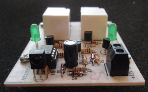
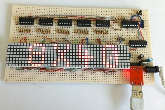
This tutorial is to introduce the microcontroller technolgy the capabilities and the specifications of a commonly used Microcontroller Microchip PIC16F877 and describe the experiments conducted using the Development board Flash PIC development board which accomodates this microcontroller.

Microchip PIC16F877 Microcontrolle

1.1.   What is a microcontroller?

A microcontroller is a compact standalone computer, optimized for control applications. Entire processor, memory and the I/O interfaces are located on a single piece of silicon so, it takes less time to read and write to extrernal devices.

1.2.   Why are microcontrollers used?

Following are the reasons why microcontrollers are incorporated in control systems:

  1. Cost: Microcontrollers with the supplemantary circuit components are much cheaper than a computer with an analog and digital I/O
  2. Size and Weight: Microcontrollers are compact and light compared to computers
  3. Simple applications: If the application requires very few number of I/O and the code is relatively small, which do not require extended amount of memory and a simple LCD display is sufficient as a user interface, a microcontroller would be suitable for this application.
  4. Reliability: Since the architecture is much simpler than a computer it is less likely to fail.
  5. Speed:  All the components on the microcontroller are located on a singe piece of silicon. Hence, the applications run much faster than it does on a computer.
  1. Getting Started

2.1.   Parts list:

The parts list and the vendor list is given in Table-2.1.1

Description   Vendor Part No. Price Qty.
FlashPIC-Development Board PRLLC FlashPIC-Dev 45.00$ 1
CCS ICD-S debugger/programmer PRLLC ICD-S 75.00$ 1
Embedded C Programming and the Microchip PICRichard H. Barnett,Larry D. O’Cull,Sarah A. CoxISBN: 1401837484  Amazon.com N/A 57.70$ 1
12VDC adapter Radioshack 273-1776 16.99$ 1
8 position dip switch Jameco 38842 0.89$ 1
Multipurpose PC Board Radioshack 276-150 $1.69 1
LM35CZ Linear Series Jameco 107107 $5.79 1
Plastic Sphere Bubblegum machine
DAC-0832 8 bit DAC Jameco 128186 3.95 1
LF353 Op-Amp Jameco 22939 $.39 1
10Kohm Resistor Radioshack 271-1335 $.99 1
20Kohm Resistor Radioshack 271-0265 $.99 2
10ohm 10W Resistor Radioshack 271-132 $1.69 1
TIP31 Power Transistor Jameco 33048 $.49 1
0.01uF Capacitor Radioshack 272-1051 $1.19 1
1N4004 Diode Radioshack 276-1103 $.79 1
100 ohm resistor Radioshack 271-1311 $.99 1
Technie Toyz 12V PC Fan Compusa MD-TTF-8025A-2B $10.99 1
9V battery Radioshack 23-875 $3.29 1
6-Ft. Serial RS-232C Cable Radio Shack 26-117 $13.49 1
1×40 pin header Jameco 103270 0.75$ 1

Note: It is assumed that the user has the following common electrical equipment: 1×8 pin ribbon cable, alligator clips, soldering iron and solder.

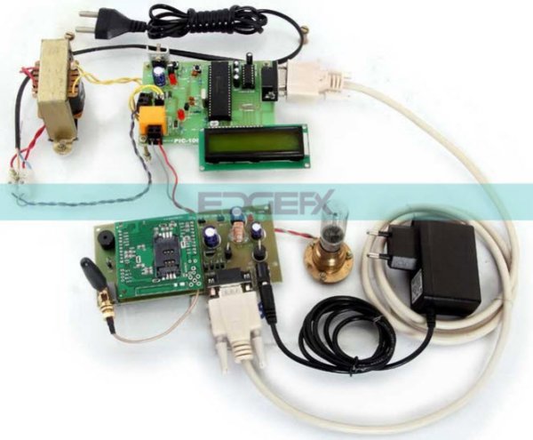
2.2.   Connecting the equipment

  1. Powering up the PIC Development Board

The PIC16F877 chip has to be powered at all times when its being programmed and running an application.

  1. Cut the connector off the DC end of the 12VDC adapter and strip the wire ends.
  2. Determine the + and – wire leads using a voltmeter.
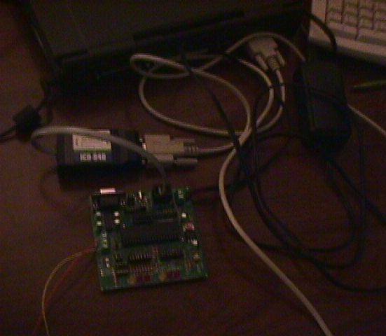
  3. Apply the 12VDC to the board by connecting the 12VDC adapter to + and – pins of J2 of Flash PIC Development Board. See Figure2.2-1

Caution: Make sure you wire the – and + ends of the adapter of the to the right pins of Jumper 2. Do not plug the adapter to 110V/AC outlet before you wire the power to the board. In order to avoid cheking the leads with a voltmeter everytime, its always a good practice to label the leads for future reference.

  1. Plug the adapter to the 110V/AC outlet.
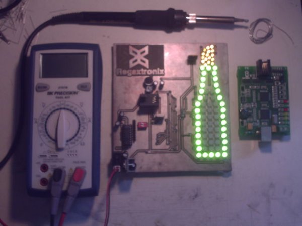
  2. Observe the green LED D9 illuminating and rest of the LEDs flashing in order.

b.Connecting the Flash PIC Development Board to a PC through ICD-S:

After we put power on the FlashPIC development board, now we are ready to program the PIC16F877 chip.

  1. Connect the ICD-S to the computer using the RS-232 cable, which came with the ICD-S.
  2. Conncect the ICD-S to the developmet board using the phone jack.
  1. Coding,Compiling and Transfering the .hex files to the chip

Now that we have our hardware setup, we are ready to write the code and transfer the .hex files to the PIC16F877.

  1. Install the CCS compiler demo version, which came with the reference book ”Embedded C Programming and the Microchip PIC” to your computer
  2. Insall the ICD software which came with the ICD-S unit.
  3. Start the CCS compiler.
  4. Go to menu path: Options>Debugger/Programmer
  5. Change the to the path of Icd.exe. (See Figure2.2-3)This would enable starting the ICD-S software via toolbar button.

6. The software setup is complete. We can type the source code and compile it and transfer the file to the PIC chip as illustrated in Figure2.0-3. After single clicking the “compile” command button on the toolbar and generating the .hex file, we can single click the “program chip” command button.

7. After the “program chip” command button is pressed the ICD V2.7 program is initiated. First we check the RS-232 communications, the ICD-S and the PIC16F877 by using the following command buttons respectively: “Check COMM”, “Test ICD”, “Test Target”. If all of them check to be OK, now we can browse and transfer the .hex file to the chip by using “Download to target Command button”. After the .hex file is transferred, now we can run the software and test its functionality by clicking on “Run Program” command button. (Figure2.2-4)

8. Since the software is tested now the ICD-S can be disconnected and the Development board can be powered up and the .hex file can be run without being connected to the computer.

  1. PIC16F877 Microcontroller

In this section, properties of PIC16F877 microcontroller,CCS compiler, ICD-S, the reference book “Embedded C programming and the microchip PIC” are briefly explained to give a general idea; it may seem confusing for a first time reader who is not familiar to microcontrollers technology or C programming. However, as the funtionality of the components such as timers, A/D converters, I/O Ports are explained in detail in Section 3 as they are being used in the experiments, the fundemental concepts would be better understood and, the reader can flashback to this section to view the schematics and the specifications.

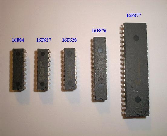
PIC16F877 is one of the most commonly used microcontroller especially in automotive, industrial, appliances and consumer applications. In Figure –1, the block diagram of the PIC16F877 is illustrated.

The core features of PIC16F877 are:

  • High performance RISC CPU
  • Only 35 single word instructions to learn
  • All single cycle instructions except for program

branches which are two cycle

  • Operating speed: DC – 20 MHz clock input

DC – 200 ns instruction cycle

  • Up to 8K x 14 words of FLASH Program Memory,

Up to 368 x 8 bytes of Data Memory (RAM)

Up to 256 x 8 bytes of EEPROM Data Memory

  • Pinout compatible to the PIC16C73B/74B/76/77
  • Interrupt capability (up to 14 sources)
  • Eight level deep hardware stack
  • Direct, indirect and relative addressing modes
  • Power-on Reset (POR)
  • Power-up Timer (PWRT) and

Oscillator Start-up Timer (OST)

  • Watchdog Timer (WDT) with its own on-chip RC

oscillator for reliable operation

  • Programmable code protection
  • Power saving SLEEP mode
  • Selectable oscillator options
  • Low power, high speed CMOS FLASH/EEPROM

technology

  • Fully static design
  • In-Circuit Serial Programming. (ICSP) via two

pins

  • Single 5V In-Circuit Serial Programming capability
  • In-Circuit Debugging via two pins
  • Processor read/write access to program memory
  • Wide operating voltage range: 2.0V to 5.5V
  • High Sink/Source Current: 25 mA
  • Commercial, Industrial and Extended temperature

ranges

  • Low-power consumption:

– < 0.6 mA typical @ 3V, 4 MHz

– 20 μA typical @ 3V, 32 kHz

–         < 1 μA typical standby current

The peripheral features of the PIC16F877 are:

  • Timer0: 8-bit timer/counter with 8-bit prescaler
  • Timer1: 16-bit timer/counter with prescaler,

can be incremented during SLEEP via external

crystal/clock

  • Timer2: 8-bit timer/counter with 8-bit period

register, prescaler and postscaler

  • Two Capture, Compare, PWM modules

Capture is 16-bit, max. resolution is 12.5 ns

– Compare is 16-bit, max. resolution is 200 ns

– PWM max. resolution is 10-bit

  • 10-bit multi-channel Analog-to-Digital converter
  • Synchronous Serial Port (SSP) with SPI. (Master

mode) and I2C. (Master/Slave)

  • Universal Synchronous Asynchronous Receiver

Transmitter (USART/SCI) with 9-bit address

detection

  • Parallel Slave Port (PSP) 8-bits wide, with

external RD, WR and CS controls (40/44-pin only)

  • Brown-out detection circuitry for

Brown-out Reset (BOR)

3.1.   Flash PIC development board

Usually, a microcontroller by itself is not sufficient to perform the intended tasks. For instance, an oscillator chip is necessary to time the programmed instructions. In order to investigate the capabilities or to test a given microcontroller, obviously it is vital to build the proper circuitary. Example: potentiometer and a power supply to simulate analog inputs or LEDs to simulate the digital outputs. Hence, some hardware and sofware vendors provide the microcontroller with the supplemantary circuit elements on the same breadboard. These boards are called Development Boards. One can also build a development board himself/herself if he/she is willing to go through the painsaking process of building the circuit.

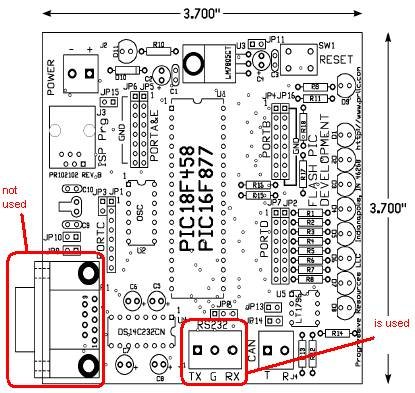
The development board used in the series of experiments is Flash PIC development board. (Figure3.1-1) It has the following features:

– RS232 through a 9-Pin D-Shell as well as screw terminals and a jumper header.

– Up to 32K words of In-System Programmable FLASH memory with up to 256

bytes of EEPROM and up to 1.5K of Internal RAM (depending on processor

selection).

– Up to 8, 10 bit, Analog Inputs, using either internal or user supplied reference.

– 9 I/O controlled LEDs, 8 of which are jumper selectable.

– 32KHz “watch” crystal for on-board Real-Time operations.

– A universal clock socket allows for “canned oscillators”, as well as a variety of

crystals, ceramic resonators, and passive terminations.

– 0.1” centered headers provide for simple connection to the processor special

function pins and I/O.

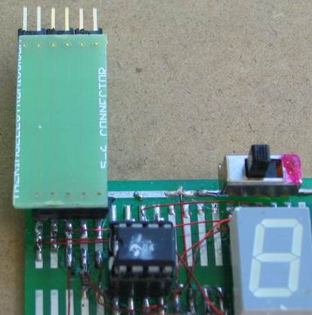
– A 6-pin, ICD connection is provided for in-system programming and debugging.

This connection is directly compatible with the Microchip ICD, ICD2 and CCS

ICD-S programming hardware. Flash PICs can also be programmed through

RS232 using an appropriate boot loader application.

– On-board regulation allows for power inputs from 8-38VDC with an LED power

indicator.

– Termination is provided for 5VDC output at 250ma

3.2.   CCS PIC-C compiler

The CCS PCW compiler is specially designed to meet the special needs of the PICmicro MCU controllers. These tools allow developers to quickly design application software for these controllers in a highly readable, high-level language.

The compilers has some limitations when compared to a more traditional C

compiler. The hardware limitations make many traditional C compilers

ineffective. As an example of the limitations, the compilers will not permit

pointers to constant arrays. This is due to the separate code/data segments in

the PICmicro MCU hardware and the inability to treat ROM areas as data. On

the other hand, the compilers have knowledge about the hardware limitations

and do the work of deciding how to best implement your algorithms. The

compilers can efficiently implement normal C constructs, input/output operations

and bit twiddling operations.

The compiler can output 8 bit hex, 16 bit hex, and binary files. Two listing formats

are available. Standard format resembles the Microchip tools and may be

required by some third-party tools. The simple format is easier to read. The

debug file may either be a Microchip .COD file or Advanced Transdata .MAP file.

All file formats and extensions are selected via the Options|File Formats menu

option in the Windows IDE.

The usage of the copiler is explained in Section 2.0 Getting started. The reference book “Embedded C Programming and the Microchip PIC” comes with a demo version of the compiler.

3.3.   ICD-S Debugger/Programmer

The ICD-S programmer is the hardware/firmware interface to burn the .hex files to the Microchip PIC. The ICD unit works with CCS’s PCW debugger or CCS’s stand-alone ICD control software. CCS’s PCW debugger is a very robust debugger integrated with PCW, and provides very detailed debugging information at the C level. The stand-alone control software allows you to quickly program target chips using ICD’s ICSP. The control software also lets you update the ICD unit’s firmware without having to remove the chip from the ICD unit. (Using these software tools requires you to have loaded the CCS-ICD firmware onto the ICD unit, which is loaded by default).

Authors note 01/22/04 : I found it odd that prllc.com does not provide a freeware program like “AVR bootloader.exe” for FlashPIC Development board as they do for Atmel AVR development board, that would enable programming the chip via serial communication connector P1 in-built to the development board. I don`t think that Development board and Compiler vendors should force the costumers to buy products like ICD-S where an option like programming via serial link exists. I have seen a program in http://sjeffroy.free.fr/Prog__PIC/BootLoader/bootloader.html which seems like it might work given the fact that bootloader file “loader.hex” pre-exists on the chip. Personally, I did not try running this program and programming the chip via RS-232.

3.4.   The Reference Book: Embedded C Programming and the Microchip PIC by Barnett, Cox and O’Cull

This book is a good guide for introducing the microcontroller technology. First chapter is dedicated to teaching basic C programming however, this book shouldn’t be considered a C programming handbook. One should always have a book like: Teach yourself C by Zhang ISBN 0-672-31861 as a C programming reference guide for beginners.

This book is designed to teach C language programming as it applies to embedded microcontrollers and to fuel knowledge in the application of the Microchip family of PIC microcontrollers. Coverage begins with a step-by-step exploration of the C language showing readers how to create C language programs to solve problems. PIC processors are then studied, from basic architecture to all of the standard peripheral devices included in the microcontrollers. Numerous worked-out example programs demonstrate common uses for each of the peripherals. Readers are subsequently introduced to the built-in functions available in C, to speed their programming and problem solving. Finally, readers are taken through use of the C Compiler, and to help custom learn to efficiently develop projects.

Included with the book is a CDROM containing samples all of the example programs from the book as well as an evaluation version of the CCS-PICC Compiler.

Author`s note 01/22/04 : In the first examples and projects in chapter 1, functions like “scanf” and “printf” are used that require prior knowledge to interface the board through RS-232 which is introduced in the late chapters of the book. It might be discouraging for the student not being able to do the first project of the book, hands-on. Although I was able to find answers to most of my questions about using the C compiler and the hardware however, I had to do a lot of skipping between chapters and Appendixes to find these answers which was time consuming. In general it is a nice and descriptive text book.

  1. Experiments

The most quick and effective way of learning a new topic is, having hands on experience. In this section we will conduct some experiments using the FlashPIC Development board to which would give us a jump start on in PIC usage.
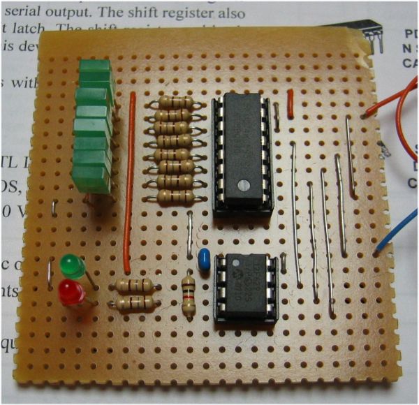
4.1.   LED Experiment

The digital I/O and the timers will be discussed with this experiment. The program will count from 0 to 255 and output the binary equivalent of this number to PortD every 2 seconds. The digital I/O peripherals are discussed in detail in the next experiment “Dipswitch”. In this experiment we will focus on the usage timers.

Timers and counters are one of the most commonly used perpheral in a microcontroller. They can be used to measure time periods, speed and provide output signals in a specified rate.

The PIC16F877 has 4 timers timer0, timer1, timer2 and watch dog timer. Timer0 and timer2 are 8 bit timers and timer1 is a 16bit timer. The inportant issue is to know when the counter reaches the maximum value (255 in 8 bit timers and 65,535 is 16bit timers) and rolls over.
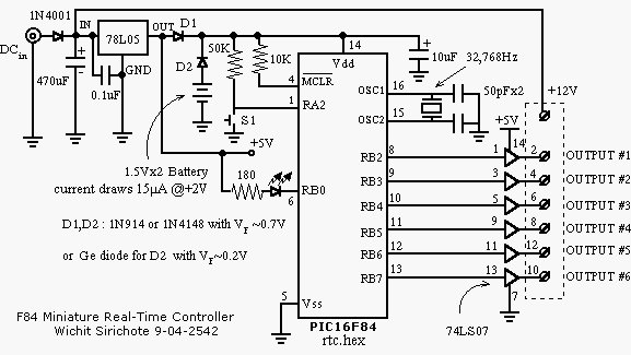
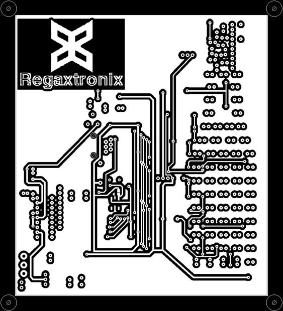
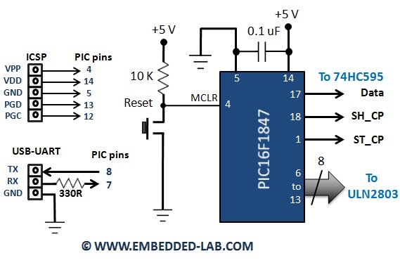
Microchip PIC16F877 Microcontrolle schemetic

The watch dog timer is a safety device. When an unepected event occurs, the watch dog timer resets the microcontroller. In this experiment we will use the watch dog timer as our timer to time the digital output.

#use delay(clock=10000000, RESTART_WDT)

The command line above, is used to tell the compiler to insert an appropriate code to automatically reload the WDT during delay functions.

“delay_ms(2000)”  command line is used to place a delay the event 2000ms in every cycle of the while loop. “output_d(z)” command line is used to output the digital number through portD.


For more detail: Microchip PIC16F877 Microcontrolle

The post Microchip PIC16F877 Microcontrolle appeared first on PIC Microcontroller.
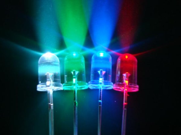
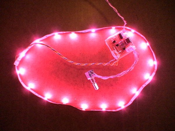
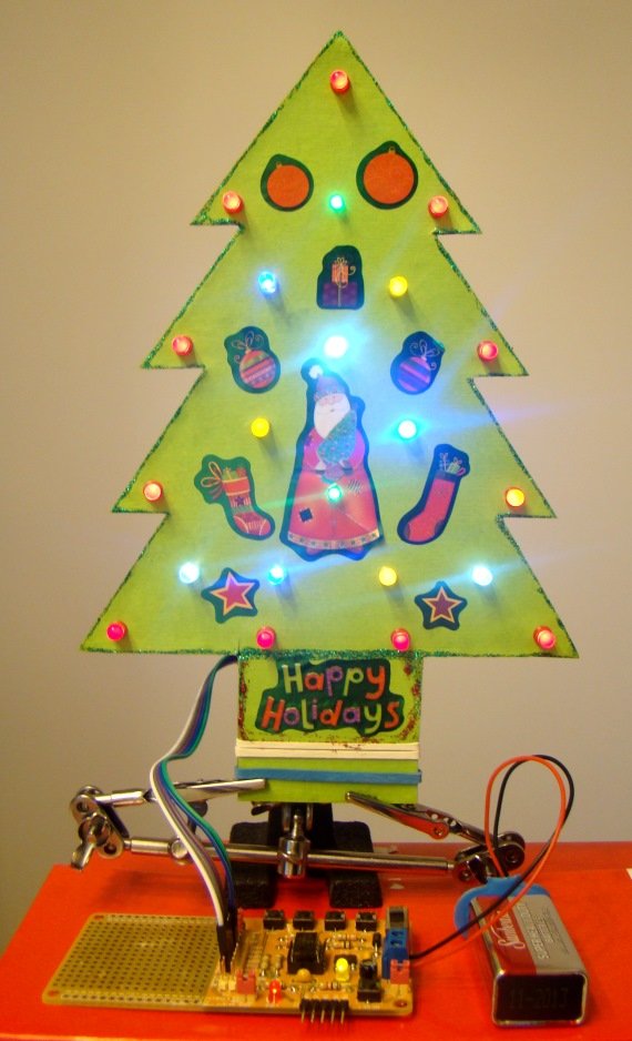
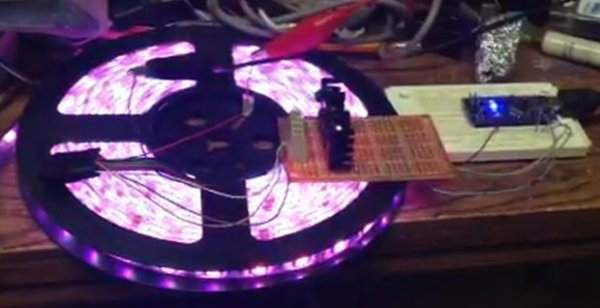
Cheap and Easy Dial Controlled High Power RGB LED(s) Driver

$
0
0

There may be a lot of RGB LED Drivers out there, but this one is a bit different, its versatile, small, cheap, and is simple to control.

A potentiometer with built in switch is used for the controls. A quick press, switches between color cycling and solid color select modes. Pressing in on the dial and holding, toggles an Intensity control, to brighten or dim the LED. Pressing in and holding again, exits Intensity control. Settings are saved when turned on/off.

It supports common anode, common cathode, or single color LEDs. Selectable via jumper wires.

The PCB is  set-up for a single 3 watt RGB LED but, it can be easily made to power a 12 volt string of LEDs in series as long as each color channel isn’t more than the recommended 2 watts ( though the transistors are rated for 2.5w ) or 500 miliamp per color channel. Correct resistor for R1, R2, R3 would have to be calculated and changed. Goto Step 7 to View.

This driver is great for ambient lights, mood lamps, display lights, case light for a PC, I have even made a lantern version that ran off 4 D batteries

And of course best of all its free, with PCB layout, HEX file, schematics are available.Cheap and Easy Dial Controlled High Power RGB LED(s) Driver

Measures 1.5″ x 1.5″ x 1″ finished.

Full Kits including 3 Watt RGB LED,  PCB, all the parts, interconnects, wire, heat sink and thermal grease. Can Be Found Here
All the parts you need. Just need a 5 volt @ 700ma+ Power Supply.

Or get a Full Kit with 0.5 Meters or 12v RGB LED strip with adhesive backing. Dial RGB LED Driver Kit, Full, RGB Light Strip

There is an Economy Kit and Basic Kit available for this project as well. For a Cheaper Project. No Headers, potentiometer or LED, see descriptions.

Get a Programmed PIC and PCB in a Combo Pack

ZIP containing HEX, PCB layout, Schematics, & datasheet is below

Download the Dial RGB LED Driver  v.1 Datasheet

UPDATE 2/15/12: A new refined version has been released.  It is recommended that devices are upgraded to this new firmware. Anyone who has purchased a kit, or programmed PIC can contact me for special price on a new version, or download the HEX from the ZIP file and re-program.

Changes v.1 to v.2:
– Faster PWM Rate
– Better Dimming down to 50%
– Color Select now goes Red -> Green -> Blue -> White (added white)
– Refined user controls
– Fixed misc bugs

I have included 2 modified versions of the firmware both use GP5 as a second button, one toggles the light on/off when the button is pressed, the other version holds the light on/off depending on the state of GP5, designed to work with a QT113 touch sensor. See readme for details.

===NOTE===
This Instructable will assume that the kit with a 3 watt RGB LED is being assembled.

If you are not using a 3 watt RGB LED, R1, R2, R3 will be different values try
led.linear1.org/1led.wiz to find the correct resistor values you should use, or send me a PM, I will help you out. Choosing incorrect resistor values can cause damage.

The author of this Instructable can not be held liable for any damage or personal loss in anyway resulting from the information in this Instructable. use at your own risk.

Common Anode – Common lead goes to V+
Common Cathode – Common lead goes to V- ( gnd )

Step 1: Prepare

Clear a work area, preferably with good light.
Layout the parts and ensure that they are all there.

Parts:
– PCB – Buy a PCB with Free Shipping
– 12F675 programmed with the firmware Or Buy One Programmed
– 8 pin DIP socket
– 3x 500 ohm 1/4 watt resistor
– 1x 10k ohm 1/4 watt resistor
– 3x NPN Transistors, I chose MPSW45ARLRAG
– 2 Pin Locking Header
– 2 Pin Housings
– 10 Crimps ( Purchased kits come with 12, just in case)
– 3 Watt RGB LED
– 10k Potentiometer, with built in momentary Pushbutton
– A regular Pot 1-10k ohm and a momentary Pushbutton can be substituted.
– 2x 4 Pin locking Header
– 2x 4 Pin housing
– Heatsink for LED
– 2 screws
– current limiting resistors for LEDs
– For a 3 watt RGB Star LED
– 1x 5.1 ohm 1 watt, for Green
– 2x 16 ohm 1 watt for Blue and Red
*Note: these need to be small resistors, 8 mm in length. I’ve only found PR010001 that fit.
though larger ones can fit, its just not pretty.
– 0.1uF disc capacitor
– 7805 if the input voltage and LED voltage is more than 7 volts.
– Wire, about 20″ of twisted pair (2 wires)

A power supply of at least 5 volts, at least 700ma ( 1 amp is better ) is also required.

Required Tools:
– Soldering Iron
– Wire Stripper
– Needle Nose Pliars

Optional:
– Hot Glue
– Electrical Tape
– Volt Meter
– Shrink Tube

Step 2: Resistors and Jumpers

Place all the Resistors First, they have no polarity so they can go in either way. Save your lead clippings for later. Placing the resistors in, and then taping them temporarily with electrical tape helps.

( figure below )
R1 – 5.1ohm 1w
R2 – 16ohm 1w
R3 – 16ohm 1w
R4 – 500ohm 1/4w
R5 – 500ohm 1/4w
R6 – 500ohm 1/4w
R7 – 10kohm 1/4w

Then place the jumpers:

Using some solid strand wire of at least 24 gauge, or some of the 1 watt resistors leads that were clipped,.

Take a needle nose pliers, bend the wire into shape pictured below.

If you are constructing the Kit, do this:
If a common anode(common positive) LED is used (3 watt star)(red lines on the figure)
J1 is jumped to NEG1
J2 is jumped to POS2

If a common cathode(common negative) LED is used  (blue lines on the figure)
J1 is jumped to POS1
J2 is jumped to NEG2

Note: If input voltage is more than 5 volts goto Step 7 for jumper details.

All types connect these:
A1 is jumped to A2
B1 is jumped to B2

Place the capacitor C1. Its non-polarized so the capacitor can go in either way, even though the top-side shows polarity.

Step 3: Transistors and Headers

Now that the jumpers, resistors and capacitor are placed. Its time for the IC socket.

The socket has a notch on it that is placed as pictured on the top side illustration on the PCB, or there is reference image below.

When soldering, ensure that there are no solder bridges to other pins, I recommend checking with a continuity meter ( volt meter) to be sure if some pads look to be touching.

The transistors position is based on if the LED(s) to be used are common anode or cathode

For common anode (3 watt Star, This one if you are assembling the Kit)
-The transistors are placed reverse of the topside illustration.  See Image Below

For common cathode
-The Transistors are placed as pictured on the topside illustration.

The full kit with a 3 watt RGB LED should not use a 7805 voltage regulator. A input of 5 volts must be used. And the solder pads for the 7805 be jumped and filled.
– Pin 1 & 3 are jumped ( the 2 outer holes of the 3) and the center hole’s solder pad needs to be filled in with solder.

If you are using interconnects or have purchased the Full Kit.
– Solder in the 2x 4 pin locking headers, they can go in either way works best.
– Install the 2 pin locking header, keeping in mind the polarity.

If you are not using interconnects
You will just solder your wire directly into the holes and
Skip the Next StepCheap and Easy Dial Controlled High Power RGB LED(s) Driver schematic

Step 4: Interconnects


The full kit
at comes with connectors to easily connect and disconnect your LED and potentiometer for easy installation into a lamp or diffusing medium.

There are 3 parts, the headers, the housings and crimp terminals.

Decide how long you need your LED wires and your potentiometer wires and cut the supplied twisted pair into 2 pieces, which you are going to make into 2 sets of 4 wires.

Trim 1/8th” of wire off each end and follow this Short Tutorial, to attach the crimps to the wire.

Once each piece has crimps on all the ends fold evenly and cut in half, so you are left with 2 pieces of double wire with 4 crimps, See images

Slide the crimps into the housings with the tabs facing the slots, they will click when they are in.
Then cut evenly in half, see 2nd image.

Repeat with second set of wires.


For more detail: Cheap and Easy Dial Controlled High Power RGB LED(s) Driver

The post Cheap and Easy Dial Controlled High Power RGB LED(s) Driver appeared first on PIC Microcontroller.

How to Create a Beer Bottle LED VU Meter

$
0
0

Create your own Beer Bottle LED Volume Unit Meter!

This instructable will show you how to create a LED beer bottle VU Meter. A volume unit meter is a device that is used to display a relative volume of audio signals. Basically, sound gets converted into electricity, then amplified and run into a dedicated IC (Integrated Circuit). The IC then determines the level of sound and outputs it accordingly onto its outputs. This particular VU Meter uses a LM3915 Dot/Bar Display Driver to determine the sound level. This circuit is more flexible than a regular VU Meter though, due to the fact that I incorporated a microcontroller into the project. This makes it a little more complex, but also way more flexible.

The main reason that I built this project is because I have always been fascinated with LEDs. There is just so many cool projects that a person can make with them. Also, a couple years ago I made a Chevrolet logo VU Meter which didn’t use a microcontroller. Although it was really cool, there wasn’t a lot that I could do with it once it was made. I had the options of bar mode or dot mode and that was it. With the help of a microcontroller, you can design a project so that you are able to turn on any individual LED or groups of LEDs at any of the 10 different sound levels. That makes things a little more challenging, but also more interesting.

By following each and every step, you will be able to complete your own beer bottle LED VU Meter just like this one. Or if you are feeling really ambitious, create your own customized LED VU Meter and just use this instructable as a guideline.How to Create a Beer Bottle LED VU Meter

Step 1: Skills Required

This isn’t a very difficult project to complete, however it does take quite a bit of time (especially if you make the PCB yourself). There are more than 330 drill holes in the PCB, 78 LEDs that have to be soldered into place and 224 SMD connections. Therefore you should possess the following skills:

– Basic knowledge of electronics
– Basic knowledge of boolean logic and digital circuits
– Know how to solder (This includes SMD parts)
– Know how to create a PCB
– Know how to program a PIC18F4550 microcontroller

Optional:
– Know how to use a multimeter (This is used if you run into errors)
– Know how to program in C
– Know how to use the MPLAB IDE and the C18 compiler

With enough time and patience, anyone can complete this project. If you are looking at this project right now and thinking that it may be too difficult for you, take baby steps and start building the smaller circuits inside of the main circuit and get accustomed to them. For example, play around with the PIC18F4550 and get to know how it works. Then play around with the LM3915 so you know how to operate it, etc. The schematic may seem intimidating, but its really not. Like most electronic circuits, it is comprised of a bunch of smaller electronic circuits all linked together.

Step 2: Tools Required

Here is a list of tools and supplies that were used to build this project:

– Solder
– Soldering Iron
– Flux Pen
– Multimeter
– Drill/Rotary Tool (If making a PCB)
– Needle Nose Pliers
– Side Cutters
– Scalpel/Utility Knife (Used for PCB touch-ups)
– PIC Programmer (I used a MPLAB ICD2 Clone)
– Anti-Static Tweezers for small SMD components
– Perfboard/Breadboard or Materials required to make a PCB
– Toothbrush and Rubbing Alcohol to clean the flux off the PCB

All of the tools are pretty basic and should be found on most electronic hobbyists workbenches.

Step 3: Components Required

Here is a list of the following electronic components required:

34x – 5mm Green LEDs
28x – 5mm Blue LEDs
16x – 3mm Yellow LEDs

2x – 1N4148 Fast Switching Diodes
1x – 1N4007 Rectifier Diode

1x – PIC18F4550 TQFP PIC Microcontroller
4x – 74HC595 SOIC 8-Bit Shift Registers
1x – LM3915N (DIP) Dot/Bar Display Driver
1x – LM7805 TO-220 +5V Regulator
2x – IRL510 TO-220 Logic Level MOSFETs
2x – MMBT2222A SOT23 Transistors

2x – 27pf 0805 Capacitors
1x – 0.1μF Ceramic Disc Capacitor
1x – 1μF Electrolytic Capacitor
1x – 4.7μF Electrolytic Capacitor
2x – 22μF Electrolytic Capacitors
1x – 47μF Electrolytic Capacitor
1x – 220μF Electrolytic Capacitor

36x – 100Ω 0805 SMD Resistors
8x – 10kΩ 0805 SMD Resistors
3x – 50Ω 0805 SMD Resistors
1x – 10kΩ SIL9 Resistor Network
1x – 10kΩ Trim Potentiometer
1x – 390Ω Through-Hole 1/4W Resistor
1x – 2.7kΩ 0805 SMD Resistor
1x – 2.2kΩ 0805 SMD Resistor
1x – 1kΩ 0805 SMD Resistor
1x – 4.7kΩ 0805 SMD Resistor

1x – RJ-11 6p6pc ICSP Connector
1x – 2-Pin 0.1″ Molex Connector
1x – 2-Pin 0.1″ Molex Header
1x – Electret Condenser Mic
1x – SMD Momentary Tactile Switch
1x – SPST Rocker Switch
1x – 2-Position DIP Switch
1x – 20MHz Through-Hole Crystal
1x – TO-220 Heat Sink

All these components I had already had on hand, but I would estimate the cost of this project to be around $40. I have shown a couple of the components used in this project in the photo.

Step 4: Schematic/PCB/Software/Data Calculator

Before we go on to how it works, I have posted the downloadable zip file below which includes:

– Circuit Schematic
– PCB Top and Bottom Layers (PDF and PNG)
– PCB Top Silkscreen (PDF and PNG)
– VU Meter Data Calculator Program
– PIC18F4550 Firmware

I thought I’d post this right away in the instructable so you have it as we go through the steps, rather than get it at the last step when we’re finished.

Step 5: How It Works

I will try to explain how it works in the next couple of paragraphs, however if you are still unclear as to how it works after reading them, check out the photos (they look really unprofessional, but they might help you understand the concept better). Just take your time and if you have any questions feel free to ask.

The first stage of the circuit is an electret mic pre-amplifer. An electret mic is great for applications like this because it is small and versatile, but it has a drawback. When it picks up sound it only puts a small signal, much too small for the LM3915 to even notice it. Therefore we have to amplify the signal of the electret microphone. The two MMBT2222A transistors are the heart of the amplifier and bring the signal of the electret mic up to a large enough value for the LM3915 to work with. Now the sound that goes into the mic gets converted into AC electricity.  In order for the LM3915 to be able to work with the amplified input signal, we need to convert the AC signal to a DC signal. This is taken care of by the 1N4148 diodes. Once the signal is converted to DC, it is fed into the signal line of the LM3915.

The second stage of the circuit is the LM3915 itself. We don’t need to actually know how the LM3915 works, we just have to know how to use it. If your curious, on page 7 of the LM3915 datasheet it shows a simplistic version of the internal wiring diagram. So, we now have a valid signal going into the IC, but how does the MCU (Microcontroller Unit) know what sound level the LM3915 is at? Well if you look at the schematic you’ll notice that each of the LM3915s outputs (LED1 – LED10) are fed into an input on the PIC18F4550. Each output is also tied high by a 10k resistor (I used a resistor network) because the LM3915s outputs are an open collector type. Meaning, the LM3915 can force its outputs into a low state (0v) but it cannot force them into a high state (+v). So when an output is not being forced low, the resistor is keeping it held high. If all of the outputs are in a high state, the LM3915 isn’t detecting any sound. If any or all of the outputs are low, the PIC18F4550 can then interpret the intensity level of the sound.

The third stage of the circuit is the PIC18F4550. The LM3915 may be the heart of the circuit, but the microcontroller is definitely the brains. This stage reads the outputs of the LM3915 and turns on the LEDs according to the sound level. The nice thing about using a microcontroller is that we can turn on any of the inside LEDs (the 28 blue LEDs inside the “bottle”) that we want. Therefore, there is an endless amount of animations that we can create and display (ok, maybe not endless…). I have also added an element to this circuit so that we can control the 16 3mm yellow LEDs which form the lemon at the top of the bottle and we can control the 34 5mm Green LEDs which form the bottle.

The fourth stage of the circuit is the 4x 74HC595’s. Once the MCU has read the sound level, it will then figure out which LEDs it wants to turn on and which LEDs it wants to turn off (this is stored in 4 bytes of data), then it will serially transmit the 4 bytes of data (one byte to each 74HC595) and latch it. Once the 74HC595’s have been latched, the individual LEDs will either turn on or off.

Step 6: Power Supply

The power supply is the most important part of any electronic device. It doesn’t matter how great the device is, having an unreliable power supply can ruin all of that. And having no power supply at all…well that just speaks for itself. In order for us to determine the requirements for a power supply we need to perform a few calculations.

In the schematic you will notice that there are 8 rows of 4x Green LEDs in series and 1 row with only two green LEDs in series, 3 rows of 5x Yellow LEDs in series and 1 row with only one yellow LED and 28x individually controlled Blue LEDs.

LED Voltage Drops:
Blue LED = ~3.3v
Green LED = ~2.2v
Yellow LED = ~1.9v

LED Current Calculations
Blue LED = (5.0v – 3.3v) / 100Ω
= 17mA per Blue LED

Green LED = (10.0v – (4 LEDs * 2.2v/LED)) / 100Ω
= 12mA per Green LED row

Yellow LED = (10.0v – (5 LEDs * 1.9v/LED)) / 50Ω
= 10mA per Yellow LED row

Max LED Current = (9 Green LED rows * 12mA/row) + (4 Yellow LED rows * 10mA/row) + (28 Blue LEDs * 17mA/LED)
= 624mA

74HC595 Current
I595 = Max 74HC595 Current Draw From All 4x 74HC595’s

ICC (Io @ 0mA) = 80uA per 74HC595

I595 = 80uA * 4 74HC595’s
= 320uA

Max PIC18F4550 Current @ 48MHz
IMCU = Max PIC18F4550 Current

IMCU = 50mA

Max LM3915 Current @ 20v (All outputs off)
ILM3915 = Max LM3915 Current

ILM3915 = 9.2mA (There was only ratings for 5v and 20v, so I chose 20v to be safe even though were running at 10v)

The last 3 values are found in each devices datasheets. I left out a few calculations where there is still current draw in the circuit just for the sake of simplicity (We got the main sources of current draw, the other few are next to negligible). We’ll make sure that we use a power supply that can supply more than the bare minimum that we need. So an approximate value of our current draw is:

Current Drawn From +10v Power Supply
Isupply = Total Current Drawn From +10v Power Supply

Isupply = 624mA + 320uA + 50mA + 9.2mA
= ~683.5mA

Checking my VU Meter when it is running at its max power consumption (All LEDs on) it draws 660mA. The reason it is lower than what we calculated is because we used the maximum current values in our calculations and not the typical current values (all those values are located in the datasheets). So at the very least, we’d want a +10v power supply that can supply 700mA. If you wanted to be safer (as I do), we’d use a +10v power supply that can handle 1.0A of current draw. The one I am currently using can actually handle up to 2.0A, which is way more than we need.

I run this VU Meter at  +10v, but it is capable of running reliably from +9v to +18v. Keep in mind that you will want to change the green and yellow LED resistor values if you use a higher voltage or you may put too much current through them and burn them out. Also, if you put a higher voltage through it you will need to use a heatsink that can dissipate the extra heat produced by the LM7805.

Step 7: Wasted Power and Heat Dissipation

Now we need to calculate the current that is drawn from the LM7805 +5v regulator so that we can calculate the power that it wastes. If you look at the schematic you’ll see that the green and yellow LEDs run right off of the +10v supply. The only components that use power from the +5v regulator are the 74HC595’s, the PIC18F4550 and the 28 Blue LEDs. So we can calculate Ireg by adding up the current draw of those components.

Ireg = Total Current Drawn From +5v Voltage Regulator
Iblue_total = Total Current Drawn From The +5v Regulator With All Blue LEDs On

Iblue_total = 28 Blue LEDs * 17mA per LED
= 476mA

Ireg = IMCU + I595 + Iblue_total
= 50mA + 320uA + 476mA
= 526.3mA

Now, because we are using a linear voltage regulator to step our voltage down from +10v to +5v for the PIC18F4550 and the 74HC595’s, we are going to have some wasted power. The larger the current draw through the linear regulator, the more power that will be wasted in the regulator. Here we will do some calculations and find the wasted power in the voltage regulator:

Vin = +10v
Vreg = +5v
Ireg = 526.3mA

Pwasted = (Vin – Vreg) * Ireg
= (+10v – +5v) * 526.3mA
= 2.63W

The power that is wasted by the LM7805 is 2.63W. Now you may be saying “Big deal, we’re not running it on a battery so we can afford to waste that power.” The only problem is that when a linear voltage regulator wastes power it turns that wasted power into heat. This is bad news for the LM7805, therefore we need to attach a heatsink to it to help it dissipate the heat that it generates. If I would have had a switching +5v regulator on hand I would have used it instead of the LM7805, simply because switching regulators are more efficient than linear regulators, which means less heat.

Step 8: LED Connections

This step builds off of Step 4: How It Works, so make sure that you understand step 4 quite thoroughly before you continue on to this step. In this step we will have a look at the PCB board and see where all of the LEDs are placed. From there we can learn how to write data to the 74HC595 shift registers and how to control the state of each individual LED inside the “bottle” (the blue LEDs).

Before we can start writing any code to control our LEDs, we first need to find out where exactly each LED is placed on the PCB. If you look at photo #2 you will see a silkscreen of the PCB board. The outside LEDs that make up the bottle shape are all green LEDs. We cannot control these individually, we can either turn them all on or all off. The same goes for the yellow LEDs that make up the lemon at the top of the bottle. Right now we are going to concentrate on the inside LEDs which are the blue LEDs that we can control individually. On the schematic all of the LEDs are labeled in a left to right, bottom to top manner.

Now, to know which LEDs to turn on we need to figure out which LED connects to which pin on which 74HC595. I have it set up so that if you count in a left to right, bottom to top manner, every 8 blue LEDs will make up one 74HC595 IC. The top 4 blue LEDs are connected to the 4th 74HC595 (IC4) and only use half of its outputs. Here are the LED connections to the 1st 74HC595 (IC1), as seen in photo #3.

QH -> LED7
QG -> LED8
QF -> LED9
QE -> LED12
QD -> LED13
QC -> LED14
QB -> LED17
QA -> LED18

The first 8 blue LEDs connect to IC1, the next 8 connect to IC2, the next 8 connect to IC3 and the next 4 connect to IC4. They all follow the same format as IC1**. Now I know what you’re thinking, “Why didn’t he wire QA to LED7 and QB to LED8 and QC to LED9…etc. instead so they all go in a straight through order?” Seems kinda backwards huh? Well the reason I chose to do it the way I did is because it made the PCB much easier to route. So I made it easier to route the hardware, but now it may make the software a little harder to write (its still quite easy).

**IC4 is actually connected up differently, I should have put the four LEDs on the upper 4 bits not the lower 4 bits. Not sure why I did that.How to Create a Beer Bottle LED VU Meter schematich

Step 9: Controlling The LEDs

Now that we understand how the LEDs are wired up, we can begin learning how to write data to each shift register so that we can control the LEDs. When we write data out of our PIC18F4550, it will first go into IC4. Then after IC4 fills up with 8 bits of data (1 byte), every bit shifted into IC4 after that will cause the MSb (Most Significant bit) of IC4 to be shifted into IC3 which will become the LSb (Least Significant bit) of IC3. So on so forth, all the way to IC1. I won’t go into great detail with this because there are already quite a few instructables here that deal with shift registers, so if you don’t fully understand the concept you can read up on them. I also posted a link to a good tutorial on 74HC595 shift registers at step #16.

Every LED is represented by 1 bit. In order to control each LED, we have to send 28 bits to the shift registers from the PIC18F4550. Seeing as we use the SPI protocol to transfer data to the shift registers, we actually end up sending 32 bits of data (4 bytes). This is because the SPI protocol only sends data 8 bits at a time with this particular microcontroller. Anyways, the extra 4 bits are not used and we will just ignore them (we’ll always leave them as 0). Once we shift the data into the 74HC595’s, we then “latch” them. Which means that whatever data we shifted into them, it will put that value (1 (high) or 0 (low)) onto its outputs. We’ll head into some examples now which may clear up some questions.

Example 1
Say we want to turn all of the blue LEDs ON. What would be the values for each byte of data we shift into each register? This is where some basic boolean logic will come into play. Seeing as these LEDs are active high (they turn on when we write a 1 to them) we have to write a 1 to turn them on or a 0 to turn them off. So if we want them all on, we would have to write this to the shift registers:

MSb         Lsb        Hex
IC1 – 1st Byte Sent -> 11111111          0xFF
IC2 – 2nd Byte Sent -> 11111111         0xFF
IC3 – 3rd Byte Sent -> 11111111          0xFF
IC4 – 4th Byte Sent -> 00001111          0x0F

So that one was pretty easy. We just made every bit that represents an LED equal to 1 (+5v). Then we’d latch the data in and it’d turn on all of the blue LEDs. Of course the 4 bits that are 0 are those ones that we are going to ignore and aren’t connected to any LEDs.

Example 2
Say we want to turn all of the blue LEDs OFF. This is another easy one, but what would we write to the shift registers?

MSb       Lsb            Hex
IC1 – 1st Byte Sent -> 00000000            0x00
IC2 – 2nd Byte Sent -> 00000000           0x00
IC3 – 3rd Byte Sent -> 00000000            0x00
IC4 – 4th Byte Sent -> 00000000            0x00

Now we just made every bit that represents an LED equal to 0 (0v). Then we’d latch the data in and it’d turn off all of the blue LEDs.

Example 3
What data would we send to turn on LED7, LED8, LED42, LED43, LED47 and LED52? All the other LEDs not mentioned should be turned off.

bit 7 —— bit 0
MSb          Lsb         Hex
IC1 – 1st Byte Sent -> 11000000           0xC0
IC2 – 2nd Byte Sent -> 00000000         0x00
IC3 – 3rd Byte Sent -> 00000110           0x06
IC4 – 4th Byte Sent -> 00001001           0x09

Once we latch it, it’ll turn on LED7 and LED8 which are bit 7 (QH) and bit 6 (QG) on IC1. Also bit 1 (QB) and bit 2 (QC) on IC3 will go high, turning on LED42 and LED 43. On IC4, bit 0 (QA) and bit 3 (QD) will go high, turning on LED47 and LED52.

Its really simple to turn on any of the inside LEDs. Just have a look at the schematic, figure out where the LEDs are that you want on and off, convert it into 4 bytes and your set. Next we’ll learn how to use functions that have been written for the PIC18F4550 to transmit the data to the shift registers.


For more detail: How to Create a Beer Bottle LED VU Meter

The post How to Create a Beer Bottle LED VU Meter appeared first on PIC Microcontroller.

Aurora 9×18 Kit

$
0
0

*** There’s an updated version of this kit available at http://www.theledart.com/blog/store ***

Responding to many requests, Aurora 9×18 Kit is now available, so this is the Instructable specific to building the kit.

Please leave comments, especially tips for successful assembly.Aurora 9x18 Kit

Step 1: Identify the Parts

First, identify all the parts contained in the kit.
Below is the parts list.

[Parts List]
qty item
1x Custom PCB
162x 150Ohm (0603)
9x 220 Ohm (0603)
3x 470 Ohm (0603)
13x 1k Ohm (0603)
1x 10k Ohm (0603)
1x 1uF (0603)
2x 10uF (0603)
1x AP7333-33 or AP7313-33 (“JZ” or “NZ” printed on it)
1x PIC24F08KA101-SS
3x DMP3098L (“DMB” printed on them)
12x MMBT2222A (“K1P” printed on them)
1x 4-way Stick Switch EVQQ7
162x Tricolor LED (common-cathode)
1x Molex 2 pin header (right angle)

Resistors have their values written on them. Two top digits followed by the number of 0’s after. So 150 ohm would have 151 written on them. Those are so small, be careful not to misplace them. I always tidy up the work area before starting assembly. Make sure you have a good lighting, too.

Capacitors do not have anything written on them, so be sure to keep them in the carrier (tape) until you are ready to solder them.

Transistors have letters printed on them, however they are codes, so the codes are noted on the list above.

Other parts are quite obvious, I think.

Step 2: Tools & Supply

  • Magnifier visor or other visual aid device (I think this is essential)
  • Tweezers (fine tip ones)
  • Solder paste in syringe*
  • Electric hot plate*
  • Soldering iron (temperature controlled)
  • Solder (flux core. go for the highest quality solder you can afford. 0.015 inch / 0.4 mm diameter recommended for SMD.)
  • Solder wick (thin braid recommended – mine is about 1.5 mm wide.)
  • Wire cutter (I recommend this one.)
  • Microchip PIC programmer (supports PIC24F08KA and capable of In-circuit programming through a standard 6-pin ICSP connector, such as ICD2, ICD3, PICKit2, PICKit3) and a computer

(* If you are doing the reflow method)

Good lighting is also very important. You can work much better when you can see the details.

Step 3: Solder the SMDs

I’ve shown the “poor man’s reflow” method using solder paste and electric griddle on the Aurora 9×18 Instructable. You can do the same, however hand soldering is still a viable option. I think hand soldering might be quicker for more experienced solderers.

* I don’t recommend Aurora 9×18 to be your first SMD project. If you have not done any SMD soldering before, please practice before taking on Aurora 9×18. Aurora 9 bar might be a good project to get your feet wet.

There are so many videos showing the SMD soldering techniques on YouTube. You might want to search “SMD soldering” and watch some. You will realize that SMD soldering is nothing to be afraid of.

(This one is very informative: http://youtu.be/3NN7UGWYmBY )

Print out the part placement guide (ideally in color) and follow the order to minimize the errors.Aurora 9x18 Kit schematich

Step 4: Inspect & Program

Once all the SMT parts are soldered, inspect carefully for bad joints and shorts.

After making sure everything is good, it’s time to program the PIC microcontroller. This part is described in the step 10 of the original Instructable. However here are the points:

  • Connect 5V power supply – you can not supply the power from the programmer, as that will stress the voltage regulator on board.
  • See the chart for the pin assignments.
  • 6th pin of the ICSP connector (LVP) is not used. Use only pin 1 – 5.
  • You need to use “High-Voltage Programming” mode, in order to write all of configuration bits required for Aurora 9×18. You will find this option in IDE, under “Programmer” menu -> “Settings”. On “Program Memory” tab, check “Use high voltage on MCLR”.
  • If you are using older programmers which output higher than 9V to program (like ICD 2), please add a voltage limit circuit to protect the PIC24F used. See the photo with my comment.
  • PICKit 2 and 3 are fine without any modifications.


For more detail:  Aurora 9×18 Kit

The post Aurora 9×18 Kit appeared first on PIC Microcontroller.

Making a mini LED Christmas tree

$
0
0
My two and a half year old son loves toys with flashing lights. For this Christmas I thought of making a mini LED Christmas tree for him. This project uses 22 multi-color LEDs which are driven by a PIC12F683 microcontroller using the Charlieplexing technique. The details of the build procedure is described in the following sections. – See more at: http://embedded-lab.com/blog/?p=8116#sthash.HFMkB7wL.dpufMaking a mini LED Christmas tree

Christmas tree control circuit

This section describes the electronics part of the project. It uses the PIC12F683 microcontroller that operates at 4.0MHz using the internal clock source and drives 20 LEDs through 5 I/O pins (GP0, GP1, GP2, GP4, and GP5) using the Charlieplexing technique. The 20 LEDs are connected to the five Charlieplexing signal lines (named A through E) as shown in the figures below. Multiple color LEDs are chosen to make the Christmas tree colorful and attractive.

– See more at: http://embedded-lab.com/blog/?p=8116#sthash.HFMkB7wL.dpuf

Construction of tree

First of all, make a paper layout of the tree and stick it on a cardboard or a foam board using glue. I am using the 0.2″ thick black foam board from Dollar Tree. Mark the places where you want to place LEDs on your Christmas tree. Next drill two holes (approximately 0.1″ apart) for LED legs at each marked LED position. Then cut the foam board along the layout of the tree. These steps are illustrated in the following pictures.

– See more at: http://embedded-lab.com/blog/?p=8116#sthash.HFMkB7wL.dpuf

Next take a construction paper (I am using Green color) for the front view of the tree. You can glue the cut foam board tree to it first and then cut the paper along the edges of the foam board. Now you will have a more colorful front look for the tree, as shown below. – See more at: http://embedded-lab.com/blog/?p=8116#sthash.HFMkB7wL.dpuf
The holes for LEDs are covered on the top with the newly added layer of the construction paper. You can extend these holes across the construction paper by inserting a sharp pin through each hole from back side to the front. Next insert LEDs from front side and bend their legs on back side for their support. The following picture shows the arrangement of LEDs in my Christmas tree. I put 11 5.0mm Red color LEDs (1-11) along the edges, and 11 more (multi-color) in the body area of the tree. This makes total 22 LEDs. The LEDs marked 1 through 20 are connected to the Charlieplexing circuit (discussed above) in the same way as described in the circuit diagram. LED 21 is connected in parallel with LED 16, and LED 22 is connected in parallel with LED 20. I added these two extra LEDs just for the symmetry of the LED distribution in the tree. – See more at: http://embedded-lab.com/blog/?p=8116#sthash.HFMkB7wL.dpufMaking a mini LED Christmas tree schematich
Note that the LED labels (1-22) in the above picture are added later with Paint.net software for readers convenience and are not printed in the actual tree. You can also decorate your tree with various Christmas shape stickers as I did. All the LED wiring are done on back side of the tree. I fixed a small piece of general purpose prototyping board on back side that carries the five Charlieplexing signal lines along with 100 Ohm resistors in series. Each LED terminals should be connected to two Charlieplexing signal lines as shown in the circuit diagram before. This is the most time consuming part of this project. The second end of the five resistors are accessible through header pins on the prototyping board. – See more at: http://embedded-lab.com/blog/?p=8116#sthash.HFMkB7wL.dpuf

For more detail: Making a mini LED Christmas tree

The post Making a mini LED Christmas tree appeared first on PIC Microcontroller.

LED scrolling Christmas tree ornament with built in video game!

$
0
0

Hello all and welcome to this Christmas tree decoration instructable.

This ornament is designed to hang on your Christmas tree just like any other decoration, but it’s just that little bit more eye catching! When you turn it on it will scroll a “MERRY CHRISTMAS” message across the 8×8 display. Not interesting enough for you? Well just grab the ornament from the tree, turn it off – hold down one of the push buttons – then turn it on and now you will be presented with (possibly) the worlds smallest Christmas tree ornament video game – SANTAS SCRAMBLE!

The game is very simple, you press one of the two push buttons (on the rear of the unit) to move santa either to the left or to the right in order to avoid the oncoming obsticles (preventing him from delivering presents to the children…) the game gets faster the further you get and will tell you what level you made it to if you crash.
LED scrolling Christmas tree ornament with built in video game
To return to the scrolling message, just turn it off then on without holding down a game button.

If you would like to buy a make it yourself kit, feel free to send me a message. Or if you would just like the circuit board on it’s own then let me know also.

The kit contents:

– 1 x PIC16f677 microcontroller (SMD)
– 1 x 8×8 bi-colour LED matrix
– 1 x coin cell battery holder
– 1 x PCB
– 2 x coin cell batteries
– 2 x 10k ohm resistors (SMD)
– 2 x mini push buttons
– 1 x mini slide switch (SMD)

The complete kit is $8.95US
PCB on its own is $3.95US

Alternatively you can download the pcb layout from the link below. It is in diptrace format you can download a freeware version of diptrace from www.diptrace.com

Step 1: Getting everything together.

First off we need to gather together all the items required to make this kit.

The kit contents:

– 1 x PIC16f677 microcontroller (SMD)
– 1 x 8×8 bi-colour LED matrix
– 1 x coin cell battery holder
– 1 x PCB
– 2 x coin cell batteries
– 2 x 10k ohm resistors (SMD)
– 2 x mini push buttons
– 1 x mini slide switch (SMD)

You will also need:

– pickit 2 (or similar programmer)
– Experience in soldering
– Soldering Iron (with a small tip)
– Solder
– Solder wick (optional)
– Flux (optional)

The solder wick is very handy when soldering surface mount components if you ever solder pads or connections together. Also, flux is unbelievably handy when you want to achieve a nice smooth finish and ease of soldering.

So fire up your soldering iron and lets get started!

Step 2: Soldering in the pic microcontroller.

The first component to solder in is the microcontroller. Now this is the trickiest component due to the close spacing of the legs on the chip. This is why I can’t emphasise enough the importance of flux. It will make soldering this chip in so much easier.

So with that said, apply some flux to both sides of where the microcontroller will solder onto.

Once done, apply a touch of solder to the top right and bottom left pads.

Then get your microcontroller and line it up with the pads. heat up the two pads that you presoldered. This will hold the microcontroller in place which will make it easy to solder in the remaining legs.

Once all legs are soldered in, it should look a little something like this picture.

Step 3: Ready for programming!

Now that you have soldered in the microcontroller you are ready to program it with the hex file.

(You can download this file from this page)

The PCB has 5 pads where you can connect your pickit programmer to. To do this you will need a five pin header. Plug this into the programmer and then you just need to ‘touch’ these pins to the pads on the circuit board.

(please note, I have the programmer around the wrong way in this photo! you need to flip the programmer around the other way!)

I am guessing that If you have your own programmer, that you have the pickit software installed on your computer.

So open up the pickit program and load the Merry_Christmas.HEX file. program it to the board and you’re done! You now don’t need to connect your programmer again, unless you want to reprogram it with your own code.

Step 4: Solder in the shorting links and slide switch.

The reason that I am using shorting links instead of SMD resistors is due to the low voltage (3volts) that powers this little project. The LEDs drop most of that 3volts and the rest is then dropped within the microcontroller. Adding any external resistance just makes the display too dim.

If you were planning on using some other power supply (such as 5volts) then you would definately want to use resistors here. (100 – 150 ohm would be perfect)

The easiest way to do this is to solder little blobs on all of the pads and then get little offcuts of wire to solder the pads together (as shown in the pic)

Next, you will need to grab the SMD slide switch. Since the slide switch has two plastic tabs underneath it, you will need to cut these off with a blade – otherwise the switch will stick up a fair way off the circuit board. (see picture)

Then solder in the switch to the position shown. Make sure you are a little more generous in the amount of solder that you use on the two sides of the switch (this is what holds it to the board)LED scrolling Christmas tree ornament with built in video game schematich

Step 5: Solder in the two 10k resistors.

Flip the board over and grab your two surface mount 10k ohm resistors (they are small so dont lose them!)

This photo shows where they need to be soldered to. Pretty much the middle of the board.


For more detail: LED scrolling Christmas tree ornament with built in video game!

The post LED scrolling Christmas tree ornament with built in video game! appeared first on PIC Microcontroller.


Temperature and relative humidity display with adaptive brightness control

$
0
0
The objective of this project is to illustrate a technique of implementing adaptive brightness control to seven segment LED displays. It consists of a closed loop system that continuously assesses ambient light condition using an inexpensive light-dependent resistor (LDR) and uses that information to adjust the brightness of the display. For the proof of concept, the technique is applied to construct a digital temperature and relative humidity meter that adapts the brightness of the seven segment LED displays to the surrounding lighting conditions. There are 8 seven segment LED displays used in this project and they are all driven by one MAX7219 chip. The ambient temperature and relative humidity are measured using the DHT11 sensor. The microcontroller used in this project is PIC12F683, which is a low-pin-count (8) device from 8-bit PIC microcontroller family. Auto-adjusting the brightness of the seven-segment LED display with surrounding illumination enhances the readability in all ambient lighting conditions.Temperature and relative humidity display with adaptive brightness control

Theory and circuit setup

Many smartphones, HDTVs, PDAs, tablets, and computer screens now come with an automatic brightness control that aims to conserve power as well as to make the display easier to see in a broad range of illumination conditions. This feature basically dims the display screen in a dark environment and brightens it when the ambient light level is higher. The brighter screen helps to counteract the effects of glare from ambient light and also takes into account for the decreased sensitivity of human eyes to brightness as the ambient light level increases.

An automatic brightness adjustment is basically a closed loop system that has the capability to assess ambient light and adjust the brightness of the display accordingly. In our project, a general purpose LDR and a fixed value resistor (10K) are connected in series between the power supply and ground pins to create a voltage dividing network, as shown in the circuit diagram below. The resistance of a typical LDR is less than 1 K? under bright lighting condition. Its resistance could go up to several hundred K? under extremely dark condition. Therefore, the voltage across the 10K resistor increases proportionally with the surrounding illumination. For the given setup, the voltage across the 10K resistor can vary from 0.1V (under dark condition) to over 4.0V (under very bright illumination). The PIC12F683 microcontroller reads this analog voltage through its AN3 (GP4) ADC channel and then sends out appropriate signals to the MAX7219 display driver to adjust the brightness of the seven segment LED displays.

The MAX7219 chip provides a serial interface to drive 7-segment LED displays (common-cathode type) up to 8 digits and requires only 3 I/O pins from microcontroller. Included on the chip are a BCD decoder, multiplex scan circuitry, segment and digit drivers, and an 8×8 static RAM to store the digit values. The segment current for all LEDs is set through only one external resistor connected between the ISET pin and power supply. However, the device also provides a digital control of the display brightness (16 steps from minimum to maximum) through an internal pulse-width modulator. To learn more about the MAX7219 device, read my previous article Serial 4-digit seven-segment LED display. In this project, the GP0, GP1, and GP2 I/O pins of PIC12F683 are used to drive LOAD, DIN, and CLK signal lines of the MAX7219.

In order to measure the temperature and relative humidity, the DHT11 sensor is used. It can measure temperature from 0-50 °C with an accuracy of ±2°C and relative humidity ranging from 20-95% with an accuracy of  ±5%. The sensor provides fully calibrated digital outputs for the two measurements. It has got its own proprietary 1-wire protocol, and therefore, the communication between the sensor and a microcontroller is not possible through a direct interface with any of its peripherals. The protocol must be implemented in the firmware of the MCU with precise timing calculations required by the sensor. I have described more about this sensor and its communication protocol in Measurement of temperature and relative humidity using DHT11 sensor and PIC microcontroller. The PIC12F683 uses the GP5 I/O pin to communicate with the DHT11.

To make prototyping easier, I am using my PIC12F Project board and my Serial 8-digit seven segment LED display in this project.Temperature and relative humidity display with adaptive brightness control schematich

Software

The firmware for this project is written in C and compiled with mikroC Pro for PIC compiler version 5.30. The subroutines for initializing the MAX7219 and sending display-digit bytes are written in a simple and understandable way so that they can be easily implemented with any other programming language. If you are not familiar with MAX7219′s internal control and display registers, I would recommend to read one of my earlier posts, Serial 4-digit seven-segment LED display. The MAX7219 allows display brightness to be controlled through software by an internal pulse-width modulator (PWM). The PWM output is controlled by the lower nibble (D3-D0) of the intensity register (address 0x0A) and allows 16 brightness levels. The zero nibble value sets the display intensity to minimum, whereas all nibble bits set to 1 selects the maximum intensity level for the display. For auto-brightness control, the ADC output of the LDR sensor is first scaled down to 0-10 (11 brightness levels) by simply dividing the 10-bit ADC count by 100. Then a look-up table is used to map the scaled brightness levels to appropriate nibble values for the intensity control register of the MAX7219. The temperature is displayed in Fahrenheit (F) scale and the relative humidity in percentage (P).


For more detail: Temperature and relative humidity display with adaptive brightness control

The post Temperature and relative humidity display with adaptive brightness control appeared first on PIC Microcontroller.

Making a 8×40 LED matrix marquee using shift registers

$
0
0
LED matrix displays provide flexibility to display text, graphics, animations, and video, and therefore, they have become a popular mean of displaying information these days. You can see them at gas stations displaying the gas prices, or in the public places displaying information, and alongside highways displaying advertisements on large dot matrix panels. This project is about constructing a mono-color LED matrix display board that consists 320 LEDs arranged in 8 rows and 40 columns. The heart of this project is PIC16F1847 microcontroller which receives data from a PC through a serial port (or USB using an USB-UART interface), and display on the LED matrix with the help of five 74HC595 shift registers.Making a 8×40 LED matrix marquee using shift registers

Theory

If you are not familiar with LED matrices at all, I strongly suggest to read my two experimental tutorials that were posted earlier: Basics of LED matrix display  and Scrolling text message on an LED matrix. The first tutorial describes the basic structure of LED matrices and the multiplexing technique of driving them to display static characters. The second tutorial is focussed more on creating animation and demonstrates the concept of displaying a scrolling message on a matrix of 16×8 LEDs. This project is basically a continuation of those two tutorials and I am hopeful it will further improve your understanding of driving a bigger size LED matrix display, both at hardware and software level. The operational part of the project hardware is described in the following section along with the circuit diagram.

Circuit diagrams

Five 8×8 square LED display modules are arranged in a linear fashion to construct an 8-row X 40-column display matrix. The LED display modules I used in this project are NFM-12883AS from Futurlec. They are common-row-cathode type, which means the cathodes of all the LEDs in each individual row are interconnected, and therefore each row pin is supposed to sink currents from eight LEDs in that row. The similar row pins of all 5 modules are further connected together and are fed to the the output sinks of an ULN2803 IC, which consists of 8 Darlington arrays. Now each output pin of ULN2803 is a sink for 40 (=8×5) LEDs in that particular row. Since ULN2803 can sink current up to 500 mA per pin, the current per LED is limited to 500/40 = 12.5 mA.

The anode terminals of LEDs are accessible through column pins. Since we are going to apply row scanning technique (read  Scrolling text message on an LED matrix), each column pin needs to source current for only one LED, as only one row is active in that column at a time. The columns are driven by the outputs of a 40-bit serial-in-parallel-out arrangement constructed by cascading five 74HC595 ICs. The 74HC595 device is an 8-bit serial-input and parallel/serial output shift register. The serial output feature allows cascading of multiple 74HC595 devices. From engineering point of view, 74HC595 may not be a good choice as column drivers because they are not meant for sourcing current for LEDs. But several experiments done by people (including me) have shown that they can drive LEDs reasonably bright, and therefore can be used as column drivers in an LED matrix project like this.

The microcontroller used in this project is PIC16F1847 from the enhanced mid-range 8-bit PIC family. It runs at 32 MHz using its internal clock source (with PLL enabled). PORTB provides ground path for individual rows (cathode) through the ULN2803 darlington pair array, whereas RA0, RA1, and RA2 pins are used to control the Data, SH_CP, and ST_CP lines of the cascaded shift registers. Pin 8 and 7 of PIC16F1847 are the default pins for UART communication. They go to the USB-UART module for serial communication with the PC. A serial terminal program running on the PC can be used to send character data to the microcontroller which saves the received information into its internal EEPROM.

I constructed the above circuit on a general purpose perforated prototyping board. You definitely need a bigger one to fit all 5 LED display modules along with other components. I used VECTOR ELECTRONICS 3-hole solder pad circuit board from Newark which is a very good quality 4.5″ x 8.08″ perfboard. An LM7805 IC is used to derive regulated +5V power supply. The power supply circuit is not shown above because it is a very common circuit and I assumed you know it.

The following picture shows the finished LED display board with an USB-UART module plugged in. [A crystal oscillator is also seen in the board but it is not really used. The microcontroller runs at 32MHz using its internal clock source. I first thought I would use an external clock, but later changed my mind but I was lazy to take the crystal off the board.]

Software
The firmware for this project is developed using mikroC Pro for PIC compiler. The program uses an 8×5 byte (=320 bits) array (Buffer[8][5]) to store the display pixel information. Each bit corresponds to one LED. The user can send message from PC to the display board using a serial terminal program. I am using Termite 2.9 program on Windows. The message sent is saved onto the PIC’s internal EEPROM. The first two EEPROM locations are reserved for a data input flag and number of characters in the message. The following sequence describes in detail how the firmware of this project works.Making a 8×40 LED matrix marquee using shift registers schematich

  1. Power is turned ON. The PIC MCU initializes the ports, and listen to its serial port. It prints a message ‘ARE YOU READY FOR YOUR INPUT? Y/N’ to serial port and the message is displayed on PC serial terminal application window. The user gets 3 seconds to send character ‘Y’. Otherwise, the MCU continues and displays the pre-stored message. The message is displayed scrolling from right towards left. The serial communication between the MCU and PC happens at 115200 bps.
  2. If the user sends ‘Y’, the MCU waits for incoming data. The MCU reads the incoming bytes until it receives ‘#’, which is an indicator of last character byte sent from the PC. The MCU then writes 1 to EEPROM location 0×00, and saves the number of bytes received at EEPROM location 0×01. The received characters are sequentially saved into sequential EEPROM locations starting from 0×02.
  3. Next, the MCU loads the character data from EEPROM into RAM and display it on the LED matrix scrolling from right to left. Each character is mapped to its graphic font which is saved in to the program memory as static array. Please read Scrolling text message on an LED matrix tutorial for more detail on LED matrix font.


For more detail: Making a 8×40 LED matrix marquee using shift registers

The post Making a 8×40 LED matrix marquee using shift registers appeared first on PIC Microcontroller.

Generic Automotive Light Effect PIC/Arduino Modules

$
0
0
These are simple modules I made with a pic 12c508 microcontroller. I use them to create different effects. The Mosfets are capable of some decent curernt with very little heating. I have used these for sequential turn signals, flashing brake lights, alternating flashers, strobe effects for leds, fade in out for a dome light etc etcGeneric Automotive Light Effect PIC Arduino Modules

Step 1: Picking a Mosfet

there are two ways to do this. Use P channel mosfets to switch the power lead or N channel mosfets to switch the ground lead.

I made an 8 channel one for a traffic advisor clone for my truck. I got a bunch of 3rd brake lights from a surplus house for $2 each. I mounted them to a piece of kindorf and used a couple of muffler clamps to hold it to the rollbar. they all share a common ground lead so P-channel mosfets were used. that requires a 2n2222 transistor to pull the gate down. if you tried to hook the gate to the micro directly the mosfets would partially turn on and heat up. the trick is to always run them fully on or off. there will be very little heating.

Step 2: Single Light Controller

this is the simplest one to build. it can be used for a third brake light flasher or sequential flasher for signal lights that have 2 bulbs in a horizontal layout. This is common on the front on many trucks i’ve seen..

Step 3: Double Light Controller

This is the one I use for Mustang/Cougar sequential turn signals and alternating headlight or taillight flashers.Generic Automotive Light Effect PIC Arduino Modules schematich

Step 4: Triple Light Controller

this one is great for those RGB light strips. You can replace the pic micro with an arduino to make it easier to experiment with. just remember to use digital pins d9 d10 and d11 to drive the mosfets. Many of those strips are common Anode style so you need to use the schematic with N-Channel Mosfets….


For more detail: Generic Automotive Light Effect PIC/Arduino Modules

Current Project / Post can also be found using:

  • led driver pic

The post Generic Automotive Light Effect PIC/Arduino Modules appeared first on PIC Microcontroller.

F84 Miniature Real-Time Controller

$
0
0

Build a simple real-time controller with PIC16F84 running at low power X-tal 32,768Hz. Daily scheduler for 6-channel resided in 64-byte EEPROM can easily be preprogrammed  using Nigel PicProg.
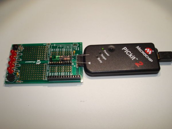
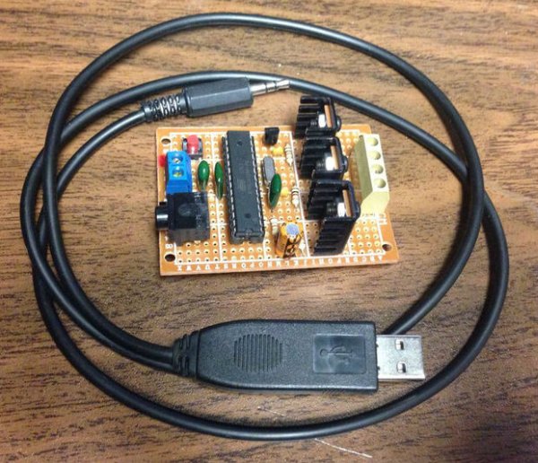
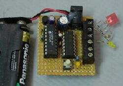
RTC2.C provides user programmable set current time without the need of recompilation.
Fixed bug on minute conversion! Introduction

F84 Miniature Real-Time ControllerThe F84 MRTC was my second design of a miniature real-time controller. This version uses PIC16F84 running with a low power X-tal 32,768Hz. The scheduler for 6-channel output was saved in EEPROM. No terminal for serial downloading of the scheduler. It’s suitable for fixed scheduler job. Two AA size battery provides +3V backup for clock operation when main power has failed. Time setting at 19:00 is set only once by pressing S1 button. The 6-channel open collector output provides max. 30mA @30V load.

Hardware

A circuit diagram of the F84 MRTC is shown in Figure 1. The controller is  PIC16F84, Flash based RISC uController running with a low-power X-tal 32,768Hz. The 6-channel output is RB2 to RB7 connected to a 74LS07 open collector buffer providing approx. 30mA @30V suitable for driving a homemade opto-triac shown in Miniature Real-time Controller 2051 version. D1 and D2 forms a simple switch between main supply and +3V battery. As can be seen, D1 may be silicon signal diode 1N914 or 1N4148. D2, however, can use a Ge diode having lower V forward. S1 is a momentary switch when pressed, it set current time to 19:00. The small LED at RB0, indicates functioning of the controller, after reset the blink rate is 1Hz, after press S1 set time to 19:00, it will blink at 1/3Hz or every 3 second.

F84 Miniature Real-Time Controller

Software

The original source program for the F84 MRTC was written using ‘C’, RTC.C with header file RTC.H. The hex file, RTC.HEX was compiled by PICC PCW V2.666. Daily scheduler is resided in 64-byte EEPROM data space. Editing for your scheduler can be made under PicPro by Nigel Goodwin. As shown in Figure 2, each byte may edit and enter into Nigel’s Picpro buffer before write the code and EEPROM data into the F84 chip. See details of setting scheduler in RTC.C.


For more detail: F84 Miniature Real-Time Controller

The post F84 Miniature Real-Time Controller appeared first on PIC Microcontroller.

PIC microcontroller led flasher circuit using PIC16F627A

$
0
0

This is microcontroller led flasher circuit using PIC16F627A as first PIC microcontroller learning of mine son. it is basic for really beginner.

Important issue,we have to make The PIC micro controller is easier. Children 8 years old, he does not understand the computer language at all.

My friends say that children should not play computer. He should try to build a lot of real electronic projects. I avoid to teach computer programming. It is difficult and tedious for him.

Thus, We start learning the micro controller with creating the one LED Flasher circuit using PIC16F627A.

It is a very simple circuit. In the past, I’ve recommended his son play Dual LED Flasher. by 2N2907PIC microcontroller led flasher circuit using PIC16F627A

The circuit diagram
First of all, Assembling the components by the circuit in Figure 1 in to the Bread board, Very few devices. The PIC16F627A is important.

All Software for PIC microcontroller
We get a pic programmer software CD for USB PIC programmer.
1. Driver for USB PIC Programmer is PICKit 2 Programmer of Microchip
2. mikroC compiler for PIC

We install both software on Windows 7 OS computer.

PIC micro controller programming

Then we will write PIC micro controller on source code (human language), with C complier code. We perform the following steps.

1. Make new folder name : One_LED_Flasher
as Figure 3 for this project only.

2. Make new project : step by step as Figure 4
(1) Click at new project
(2) Fill in name project
(3) Browse folder of this project
(4) Select Device : PIC16F627A
(5) Set clock : 3.579545 MHz as we use crystal in circuit.
(6) Set Device Flags: to Default
(7) Click OK to finish this step

3. Typing simple one LED flasher CODE into a blank board below.

main()
{
TRISB = 0xFE ;
while(1)
{
PORTB = 0x01;
Delay_ms(2000);
PORTB = 0x00;
Delay_ms(2000);
}
}PIC microcontroller led flasher circuit using PIC16F627A schematich

4. We will build Project…as Figure 6
(1) Click save all
(2) Then Click Build Project button (Ctrl+F9)
(3) Look at message text as Success

5. Open the PICKit 2 Programmer to write HEX code (machine language) to PIC16F627A as Figure 7 we apply the PIC16F627A to socket on the Programmer tool. Next take the usb cable to computer. The LED power on display. We will look at “PICKit 2 found and connected. PIC Device Found. Show Device: PIC16F627A.


For more detail: PIC microcontroller led flasher circuit using PIC16F627A

The post PIC microcontroller led flasher circuit using PIC16F627A appeared first on PIC Microcontroller.

Emergency Vehicle LED Light

$
0
0

Described here is a low-component count Emergency Vehicle LED Light circuit which can be used for capturing the attention of (or warning) drivers and pedestrians. These type of lighting gadgets kindle an instant response that makes people look up and pay attention -an important consideration when a matter of moments can mean life or death in an emergency situation. It is 100% suitable for emergency vehicles of all types, police and first responders. The bright LEDs ensure the vehicle is clearly visible, even in bad weather conditions.Emergency Vehicle LED Light

Schematic of the Emergency Light Circuit

Note that there’s no external crystal is used so it works on PIC12F675 micro-controller’s internal 4MHz oscillator.

About Initial Test!

Initial test was carried out using 2 white LEDs with current limiting resistors on a breadboard. Please check the unedited video. Note that this video is of very poor resolution, for which i deeply regret.

The circuit is wired around the popular and less-expensive PIC microcontroller PIC12F675 (IC1) and a bunch of 6 white LEDs (LED1 – LED6) to produce an alternating flashing effect (near-replica of the famous US police signal light). It can be powered from the 12V automotive battery. After construction and testing, try to enclose the entire circuit in a suitable polycarbonate (or similar) box with enough accessories like small reflectors, two color (usually Red & Blue) transparent cover plates, and mounting hardware, etc.Emergency Vehicle LED Light schematich

Enclosure idea

The program written in C (not included here), and compiled using MicroC PRO for PIC enables IC1 to flash one branch of LEDs 3 times then the other branch of LEDs 3 times, endlessly. Ready-to-use Hex Code required to program the PIC micro-controller (IC1) is available here (author’s Google Drive) for free download: http://goo.gl/TKPllt


For more detail: Emergency Vehicle LED Light

The post Emergency Vehicle LED Light appeared first on PIC Microcontroller.

Test For Presence of Internal Oscillator Calibration Word for PIC12F629

$
0
0

Description

The PIC 12F629 and 12F675 devices have an internal 4Mhz oscillator that enables the devices to be used without an external crystal or RC network.  This frees up one or two pins for I/O use and allows the device to be built into minimum component count designs.

Problems arise if by accident or otherwise, the factory programmed oscillator calibration word, located at program memory address 0x3FF is erased or over written.  If application code tries to read the calibration word and it has been erased, the code will normally crash.

It turns out that erased calibration words on the 12F629/675 PIC are the cause of almost all queries relating to code on my website that uses a 12F629/675.  People using JDM type programmers and associated software seem to have this problem more than most.  This is, in part I suspect, due to the free software / cheap hardware used by the JDM programmer that attracts inexperienced users.

Internal Oscillator

My advise to people with problems is to put the PIC into their programmer hardware and read out the program memory to see if the calibration word is present.  However, experience again shows that many users just become even more confused so I’ve written this application to give a quick Good/Bad test of the calibration word.  There’s also an optional bit of hardware that will display the value of the calibration word if it’s present.


How it works

If the calibration word has been erased, when the application code tries to read it, instead of returning with the calibration value, it wraps back round to the start of program memory as if it had been reset.  When the PIC starts after a Power-on-reset (POR)  certain internal registers are initialised to known values.  If the code wraps back round to the reset vecotr because of a missing calibration word, unlike the Power-on-reset, these registers are not initialised.

The application use the fact that this wrap-around doesn’t affect the internal registers so if we alter the value in a specific register after a power-on-reset we can tell if it has had a Power-on-reset or the code has wrapped back round due to a missing calibration value.

The code indicates the result of the test as Good/Bad by blinking an LED; green LED meaning the calibration word is present, and red LED if it has been erased.

With some extra hardware around a 74HC595 it can also display the value of the calibration word, if present, as a binary number using eight LEDs.  This is optional and the good/bad test works without it being present.

For the basic calibration good / bad test, you only need to build the circuit on the left of the dotted line in the schematic. I deliberately kept it simple so you can quickly and easily build the test circuit.

The circuit around 74HC595 is only used to display the binary value of the calibration word. I added it for a bit of fun, you don’t need it if you just want to test for the presence of the calibration word.

Software

Download HEX code  (for use with either 12F629 or 12F675)

Source code ASM (if you want to see how it works)

For more detail: Test For Presence of Internal Oscillator Calibration Word for PIC12F629

The post Test For Presence of Internal Oscillator Calibration Word for PIC12F629 appeared first on PIC Microcontroller.


Remote controlled LED lighting effects

$
0
0

LED’s have become most important component in lighting industry due to its miniature size and less power consumption. Also LED lights are lot more attractive than the primitive lights used once. This project focused on building an remote controlled LED with multiple lighting effects. Imagine setting the mood of your room using remote, will be cool isn’t it.Remote controlled LED lighting effects

DESIGN OF RECEIVER AND CONTROLLER:

The receiver and Controller part comes with TSOP1738, a receiver capable of receiving IR beam of 38Khz which is the operating frequency of a normal household remote. This receiver acts as an activator for the controller connected to it. PIC12F1822, a 8 pin low end microcontroller is deployed as a controller in this project. Other low end microcontrollers can also be used for this purpose.

The Microcontroller cannot produce enough current to drive a large set of transistors. So we are using a Transistors as a driver element in this circuit, RA2 pin from the controller feeds the signal to the base of these transistors. The reason for using two individual transistors is to create attractive effect when driven by a pulse from the Microcontroller. When the Pulse from MCU is Logic 1 Q1 will activate the LED’s connected to it, when it was logic 0 Q2 will activate all the LED’s connected to it.

TSOP 1738:

TSOP1738 is a simple IR receiver capable of receiving IR pulses of frequency 38Khz. The output of this component is active low which means that this component gives low output when IR beam is incident on it and high output in the absence of IR beam. Refer the “Datasheet” for more information about this component.

METHODS TO IMPLEMENT MULTIPLE EFFECTS IN LED LIGHTS:

We are going to add effects using two methods in this project. You can choose the method you find it comfortable to use.

1) USING INBUILT PWM:

This is a pretty old trick in sleeves of every designer when comes to controlling. The PIC12F1822 has an inbuilt PWM module using which we are going to control the illumination of led.Remote controlled LED lighting effects schematich

CODE:

  1. #include <main.h>
  2. #bit TRIS_PIN1=0x8C.0
  3. #bit PIN1=0x0C.0
  4. void main()
  5. {
  6. int16 i=0;
  7. TRIS_PIN1=1;
  8. setup_timer_2(T2_DIV_BY_16,255,1); //819 us overflow, 819 us interrupt
  9. setup_ccp1(CCP_PWM|CCP_SHUTDOWN_AC_L|CCP_SHUTDOWN_BD_L);
  10. while(TRUE)
  11. {
  12. set_pwm1_duty(i);
  13. if((PIN1==0)&&(i<=600))
  14. {
  15. i=i+100;
  16. }
  17. else if((PIN1==0)&&(i>600))
  18. i=100;
  19. }
  20. }


For more detail: Remote controlled LED lighting effects

The post Remote controlled LED lighting effects appeared first on PIC Microcontroller.

Power MOSFET RGB LED PWM Driver for PIC12F683

$
0
0

Description

Since I published the original RGB LED driver (photo right) I’ve had many enquiries from people asking how they could make the original board work with more LEDs.  I’d already made a couple of custom boards up for myself, so I finally decided it was time to put together one for the website.

MOSFET RGB  LED PWM Driver

The RGB LED driver described on this page uses logic level ‘N’ channel MOSFETs which allow it to control LED arrays or lamps at up to 5 amps per channel without heatsinks.

The driver uses exactly the same firmware as the small RGB LED driver  so you can use the same code and sequences with this board to control big arrays of LEDs.

Piranha LED colour bar

Here’s a one off light bar I built using 20 Piranha RGB LEDs and the (prototype) MOSFET driver board.  Assembled into a 25mm x 50mm x 1000mm aluminium ‘U’ section.  This was fitted under a wall shelf to illuminate the floor.  It’s very bright and gives a nice even illumination without any additional diffuser.

Circuit Description

This circuit is essentially the same as the smaller RGB driver using the 5mm LEDs elsewhere on this website except that this version uses high power MOSFETs capable of sinking 5 amps on each channel without heatsinks (at 5amps the MOSFETs will run hot)

The input power to the board must be regulated DC and be capable of suppling the power requirements of the output load.

The circuit will operate from a supply voltage in the range 9 to 24 volts.  This voltage range is dictated by the input requirements of the 78L05 voltage regulator and capacitors C3/4.

Switch S2 is not used with the firmware on this website and you do not need to fit it.  I’ve incorporated it the PCB design because I’ve written some customized versions of the code that did require two switches.

How much power can it handle?

During testing I connected the controller to some 50W / 12Volt halogen downlight bulbs, one on each channel then ran them at 100% PWM duty cycle.

Ambient temperature during test 22oC
MOSFET temperature after 5mins (measured on metal tab) 52oC
Current (sink per channel) 4.4A
Voltage drop across MOSFET Source-Drain terminal (measured) 20mV

Based on these measurements and the specification of the MOSFETs and PCB connectors, the controller should comfortably handle 5 amps per channel.  While the individual MOSFETs could handle more current, the PCB screw terminal connectors are rated at 16 amps and since there is only a single Ground connection to the board, total load for the three RGB channels should not exceed this.


PCB

PCB only option is available to buy
from the on-line shop page

Component List

Buy the complete kit for this project from the Picprojects on-line shop page

You can buy all the parts needed to build this project from most component suppliers world wide. In the UK you can get everything from Rapid Online and I’ve included a parts list with their part numbers below.


For more detail: Power MOSFET RGB  LED PWM Driver for PIC12F683

The post Power MOSFET RGB LED PWM Driver for PIC12F683 appeared first on PIC Microcontroller.

PIC Microcontroller Basics and Applications for Engineeing Students

$
0
0

The microcontrollers plays an essential role in the embedded industry  after the development of Intel 8051. The research in the field of embedded  industry gave high efficient, low power consumption microcontrollers. The Arm, AVR and PIC microcontrollers are the prime examples. These microcontrollers are getting smart with communication protocols such as I2C, USB, SPI,CAN and Ethernet. In the year 1998, microchip technology developed microcontrollers with new complex architecture and superior inbuilt peripherals. PIC microcontroller is based on Hardward Architecture and these microcontrollers are widely used for industrial purposes due to its high performance and low power consumption.The applications of this microcontroller mainly involves in PIC microcontroller projects.This article discusses about the PIC microcontroller projects, that are listed below.PIC Microcontroller Basics and Applications for Engineeing Students

PIC Microcontroller Projects

PIC microcontroller gives a fantastic way of making projects. This microcontroller is a processor with built in memory & RAM, these are used to control the projects. PIC microcontroller has various useful built in modules like timers, EEPROM, UART and analog comparators.Even with just these four modules we can build many PIC microcontroller projects.

PIC Microcontroller based Solar Photovoltaic Power Measuring

The main goal of this project is to measure solar cell parameters through various sensor data acquisition. This project uses a solar panel that always monitors the sunlight, and the different parameters of the solar panel like current, voltage, temperature and light intensity are monitored  using a PIC microcontroller. The light intensity is measured using an LDR sensor. Similarly, the current by current sensor, voltage by voltage divider principle and the temperature by temperature sensor. All these data are displayed on the LCD display, which is interfaced to the PIC microcontroller.

Auto Intensity Control of Street Lights using PIC Microcontroller

The main aim of this project is designed to control the auto intensity of street lights. This project uses LEDs  in the street lighting system, because LEDs consumes less power as compared to the conventional HID lamps.The PIC16F8 microcontroller is used to control the light intensity by developing PWM signals that makes a MOSFET to switch the LEDs to achieve the desired operation.A bunch of LEDs are used to form a street light. The PIC microcontroller contains programmable instructions to control the light intensity based on PWM signals generated. The intensity of the lights are kept high during the peak hours, as the traffic on the roads tend to decrease slowly in the late nights, the light intensity will decreases progressively till morning.Finally, it shuts down at morning and again continues at evening.

PIC Microcontroller based Medication Reminder

The main intention of this project is to design a medication reminder using PIC microcontroller. This project helps to remind a patient to take medicine at the arranged time and also displays the name of the medicine. This project is very helpful for old people and also who are very busy. A patient can store the particular time of a medicine through a matrix keypad. Based on the clock interfaced to the microcontroller, the programmed time for the medicine is displayed on the LCD. A buzzer is used to give an alert to the patient to take the medicine.

Pre Stampede Monitoring and Alarm System using PIC Microcontroller

The main goal of this project is to design a pre warning system to avoid stampede in places where a large crowd of people takes place. This proposed system warns in advance to authorities about the gathering of people in a particular place before any stampede occurs. This project uses a large number of pressure switches that are interfaced to a PIC microcontroller. When a certain number of switches are pressed, then the microcntroller generates an o/p to switch on a buzzer to give an alert to the authorities about a possible stampede.The status is also displayed on the LCD display.PIC Microcontroller Basics and Applications for Engineeing Students schematich

RFID Based Device Control and Authentication using PIC Microcontroller

This project is used to provide security in an organization by letting only the authorized person to access the secure area. This project uses RFID technology that contains an IC, used for processing and storing information and modulating and demodulating the RF frequency signal which is being transmitted. Once the person shows the RFID tag to the card reader, it scans the information stored in the tag and compares it with the data stored in the system. When the data matches with that in the microcontroller, the load will be turned ON  which is driven by a relay and it displays a message and ldquo;”AUTHORIZED” and rdquo; else states “UNAUTHORIZED” and doesn’t allow access.


For more detail: PIC Microcontroller Basics and Applications for Engineeing Students

Current Project / Post can also be found using:

  • microcontroller programming and project led

The post PIC Microcontroller Basics and Applications for Engineeing Students appeared first on PIC Microcontroller.

LED FX using PIC12F629 Microcontroller

$
0
0

This project produces a number of effects on a set of three LEDs.
You can also produce your own sequence and store it by using the 3 buttons.
You can build the project on Matrix Board or buy a complete kit with pre-programmed chip.
You can also program the chip yourself and use this project as the beginning to: “learning to write your own programs.”

6 Pin 5 Pin Connector

This project takes the place of a number of flashing circuits and can be set so that any of the sequences will show when the circuit is first turned on.
The main purpose of the project is to teach programming, however it also offers a challenge to constructors as it is laid out on matrix board, using surface-mount components. .
We have used SM components for convenience AND for ease-of-use. Once you start using them you will never go back to through-hole components. They are smaller, neater and make a very compact design.
They also make the project look simpler as they “disappear” under the board; or if you are developing a single-sided project, they reduce the size of the final design appreciably.
So, we have two areas of interest. Constructions and programming and it’s up to you to take it on.
The project is designed for all sorts of uses, including models such as train layouts, alarms and similar effects.
It can also be expanded to accept more LEDs and these can be placed on a separate display board.
But the real thing we want to get across, is programming.
This is another example of using a simple 8 pin chip to provide a number of features that would take many logic chips (such as counters and gates) and lots of components to duplicate.
It also highlights our method of hand-coding as an effective way to produce a program.
It is doubtful if the same effects could be produced on any of the pre-packaged microcontroller modules, using a tiny 8 pin chip.
This project uses about 400 instructions to produce the effects and it uses the EEPROM to store the sequence produced by the user (sequence 1) – and show it at turn-on.
In this respect, some of the sub-routines in the program are quite complex and suitable for the advanced programmer. However, if you are a beginner, you can read through the program and most of the sub-routines will be easy to follow as each line of code is explained. You have to start somewhere and this project offers a challenge.
Most projects with a program of this complexity are only available as a pre-programmed chip or only the hex code is available. There is usually no attempt at educating the reader in programming.
That’s the difference between our projects and all others.
We offer a learning curve.
For every hour of effort you put into reading, building and using one of our microcontroller projects, you get the experience of 100 hours of effort that has been put into the design to make it appear simple.
All you have to do is start . . .


For more detail: LED FX using PIC12F629 Microcontroller

Current Project / Post can also be found using:

  • led fx pic16
  • pic led circuit

The post LED FX using PIC12F629 Microcontroller appeared first on PIC Microcontroller.

PIC Projects using pic microcontroller

$
0
0

  • Some of the various PICs from Microchip, 16F84, 16F627, 16F628, 16F876 and a 16F877.

  • So far, I have only played around with the PIC16F84 PIC chip, with exception to using a PIC16F876 with the HamHUD. I have found the most documentation is on the 16F84. I have also found the most homebrew programmers for this PIC. I am starting to use 16F877 PICS now for larger projects. I mainly have to write for these in another compiler other than Hi-Tech’s because I do not have a full registered version ($850). Below, I have posted a pinout diagram I created in MS Paint. I usually get most of my PICs and ocillators from Digi-Key

PIC ProjectsIt’s fun to make the PIC do simple things like making LEDs blinks and related projects, but I like to do more exciting things, like using an LCD. If programmed right, the 16F84 can be a very usefull in many different applications. Below is another pinout I created to show the 14 pin serial/power inputs for the LCD. It uses an industry standard chipset (Hitachi HD44780). Any LCD using this chipset can be used. A great source of cheap, high quality LCDs is Crystalfontz

  • Here is the basic wiring for an LCD to a PIC16F84. This is the most basic wiring diagram. This is a 4 bit interface. It uses PORT B pins 0-3 for the data input. Most engineers like to add a cap at pin 5 of the PIC and take the PIC side of the cap to ground. Also adding a 4.7K limiting resistor to pin 4 of the PIC can help from voltage jolts, I personally have not experienced this. This circuit has much design flexability and a lot can be added if wanted. Mosty protection components.

  • Here is the programmer I use to program my PICs. It’s called the P16PRO40. This was a cheap programmer kit that only cost me $25. The programmer itself was about $15 but I opted for the extra ZIF socket (Zero Insertion Force Socket) which cost about another $6 or so, plus shipping brought it up to about $25. It can be found at Amazon Electronics. It’s under the Soldering Required Kits – Microcontrollers and Programmers. This programmer will program almost every PIC out there.

HI-Tech’s C compiler

  • I have started to use a C compiler for PIC programming provided by www.htsoft.com. It’s a demo or student version that is not limited to function as far as programming commands but it will only allow for code to be written for the 16F84 and 16C84 PICs.
  • So far I have not had much luck since this type of C programming is completely new to me. It is NOT C++, not even close if you ask me. HTLPIC sets up differently from other PIC C compilers. It requires more lines of set-up code at the top of the program file.
  • Such as, __CONFIG(x), this command tells the compiler what configuration to load for the particular processor. In this case we are talking about the 16F84, so __CONFIG(0xnnnn) is the configuration command required. This command is unique to the particular processor.
  • The CONFIG word determines what initial features are activated on the PIC, such as, Watchdog Timer, Code Protection, What type of occillator. The the configuration word is represented in HEX

PIC Projects

  • The syntax is very basic: __CONFIG(0xnnnn); //nnnn being the HEX value
  • Some examples: __CONFIG(0x3FF1);
  • This was my first sucessful project with a PIC chip. I used a 16F84 with a 10MHz resonator with built in caps.

  • Click here to view the source code to this project. The code is written in Hi-Tech C.
  • Click here to download the source code to this project. File has a “.c” extension.

  • Here is a neat PIC project that I created using the 16F84 chip and a neat little bi-color LED from Radio Shack. The LED can be red or green depending on the bias of the diode. By using two of the PORT B pins, I can control the bias of the LED. If the LED is on PORT B, Pin 0 and Pin 1, I can set Pin 0 HIGH and Pin 1 LOW, this would make the LED light red. If Pin 0 is set LOW and Pin 1 is set HIGH, the LED will light green. PORT B has 8 pins, so I was able to connect up to 4 LEDs and have full control of them all (as seen in the schematic).

For more detal: PIC Projects

The post PIC Projects using pic microcontroller appeared first on PIC Microcontroller.

Viewing all 387 articles
Browse latest View live


<script src="https://jsc.adskeeper.com/r/s/rssing.com.1596347.js" async> </script>