WARNING: Some people try to build this with an optocoupler with zerocrossing coz ‘that is better’ right? Some are even told in electronics shops it is better to use such an optocoupler. WRONG. This will only work with a random fire optocoupler: NOT igniting at zerocrossing is the principle of this dimmer.
Switching an AC load with an Arduino is rather simpel: either a mechanical relay or a solid state relay with an optically isolated Triac. (I say Arduino, but if you use an 8051 or PIC16F877A microcontroller, there is stuff for you too here.)
It becomes a bit more tricky if one wants to dim a mains AC lamp with an arduino: just limiting the current through e.g. a transistor is not really possible due to the large power the transistor then will need to dissipate, resulting in much heat and it is also not efficient from an energy use point of view.
Phase cutting
One way of doing it is through phase control with a Triac: the Triac then is fully opened, but only during a part of the sinus AC wave. This is called leading edge cutting.
One could let an Arduino just open the Triac for a number of microseconds, but that has the problem that it is unpredictable during what part of the sinus wave the triac opens and therefore the dimming level is unpredictable. One needs a reference point in the sinus wave.
For that a zero crossing detector is necessary. This is a circuit that tells the Arduino (or another micro controller) when the sinus-wave goes through zero and therefore gives a defined point on that sinus wave.
Opening the Triac after a number of microseconds delay starting from the zero crossing therefore gives a predictable level of dimming.
Pulse Skip Modulation
Another way of doing this is by Pulse Skip Modulation. With PSM, one or more full cycles (sinuswaves) are transferred to the load and then one or more cycles are not. Though effective, it is not a good way to dim lights as there is a chance for flickering. Though it might be tempting, in PSM one should always allow a full sinuswave to be passed to the load, not a half sinus as in that case the load will be fed factually from DC which is not a good thing for most AC loads. The difference between leading edge cutting and PSM is mainly in the software: in both cases one will need a circuit that detects the zero crossing and that can control a triac.
A circuit that can do this is easy to build: The zero crossing is directly derived from the rectified mains AC lines – via an optocoupler of course- and gives a signal every time the wave goes through zero. Because the sine wave first goes through double phased rectification, the zero-crossing signal is given regardless whether the sinus wave goes up through zero or down through zero. This signal then can be used to trigger an interrupt in the Arduino.
It goes without saying that there needs to be a galvanic separation between the Arduino side of things and anything connected to the mains. For those who do not understand ‘galvanic separation’ it means ‘no metal connections’ thus —> opto-couplers. BUT, if you do not understand ‘galvanic separation’, maybe you should not build this.
The circuit pictured here does just that. The mains 220Volt voltage is led through two 30k resistors to a bridge rectifier that gives a double phased rectified signal to a 4N25 opto-coupler. The LED in this opto-coupler thus goes low with a frequency of 100Hz and the signal on the collector is going high with a frequency of 100Hz, in line with the sinusoid wave on the mains net. The signal of the 4N25 is fed to an interrupt pin in the Arduino (or other microprocessor). The interrupt routine feeds a signal of a specific length to one of the I/O pins. The I/O pin signal goes back to our circuit and opens the LED and a MOC3021, that triggers the Opto-Thyristor briefly. The LED in series with the MOC3021 indicates if there is any current going through the MOC3021. Mind you though that in dimming operation that light will not be very visible because it is very short lasting. Should you chose to use the triac switch for continuous use, the LED will light up clearly.![Arduino controlled light dimmer]()
Mind you that only regular incandescent lamps are truly suitable for dimming. It will work with a halogen lamp as well, but it will shorten the life span of the halogen lamp. It will not work with any cfl lamps, unless they are specifically stated to be suited for a dimmer. The same goes for LED lamps
If you are interested in an AC dimmer such as this but you do not want to try building it yourself, there is a somewhat similar dimmer available at www.inmojo.com, however, that is a 110 Volt 60Hz version (but adaptable for 220 50Hz), that has been out of stock for a while. You will also find a schedule here.
NOTE! It is possible that depending on the LED that is used, the steering signal just does not cut it and you may end up with a lamp that just flickers rather than being smoothly regulated. Replacing the LED with a wire bridge will cure that. The LED is not really necessary. increase the 220 ohm resistor to 470 then
STOP: This circuit is attached to a 110-220 Voltage. Do not build this if you are not confident about what you are doing. Unplug it before coming even close to the PCB. The cooling plate of the Triac is attached to the mains. Do not touch it while in operation. Put it in a proper enclosure/container.
WAIT: Let me just add a stronger warning here: This circuit is safe if it is built and implemented only by people who know what they are doing. If you have no clue or if you are doubting about what you do, chances are you are going to be DEAD! DO NOT TOUCH WHEN IT IS CONNECTED TO THE GRID
Materials
Zerocrossing
4N25 €0.25 or H11AA1 or IL250, IL251, IL252, LTV814 (see text in the next step)
Resistor 10k €0.10
bridge rectifier 400 Volt €0.30
2x 30 k resistor 1/2 Watt (resistors will probably dissipate 400mW max each €0.30
1 connector €0.20
5.1 Volt zenerdiode (optional)
Lamp driver
LED (Note: you can replace the LED with a wire bridge as the LED may sometimes cause the lamp to flicker rather than to regulate smoothly)
MOC3021 If you chose another type, make sure it has NO zero-crossing detection, I can’t stress this enough DO NOT use e.g. a MOC3042
Resistor 220 Ohm €0.10 (I actually used a 330 Ohm and that worked fine)
Resistor 470 Ohm-1k (I ended up using a 560 Ohm and that worked well)
TRIAC TIC206 €1.20 or BR136 €0.50
1 connector €0.20
Other
Piece of PCB 6x3cm
electric wiring
That is about €3 in parts
Step 1: Arduino controlled light dimmer: The PCB
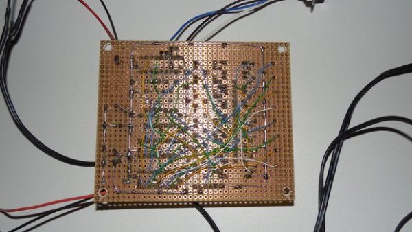
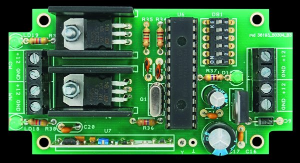
You will find two pictures for the PCB: my first one, that I leave here for documentation purposes and a slightly altered new one. The difference is that I left out the zenerdiode as it is not really necessary and I gave the LED itś own (1k) resistor: it is no longer in series with the Optocoupler, that now has a 470 Ohm resistor. I made the PCB via direct toner transfer and then etched it in a hydrochloric acid/Hydrogenperoxide bath. There are plenty of instructables telling how to do that. You can use the attached print design to do the same. Populating the print is quite straightforward. I used IC feet for the opto-couplers and the bridge rectifier.
Download the print here.
Note: You need Fritzing for this. For the direct toner transfer, the printed side of the printed pdf file, goes directly against the copper layer for transfer. Once it is transferred, you will be looking at the ink from the other side and thus see the text normal again. I made slight alterations in thePCB: I removed the zenerdiode and the LED is no longer in series with the optocoupler.
I used a TIC206. That can deliver 4 amperes. Keep in mind though that the copper tracks of the PCB will not be able to withstand 4 Amperes. For any serious load, solder a piece of copper installation wire on the tracks leading from the TRIAC to the connectors and on the track between the two connectors.
In case it is not clear what the inputs are: from top to bottom on the second picture:
+5Volts
Interrupt signal (going to D2 on arduino)
Triac signal (coming from D3 on Arduino)
Ground
NOTE:
If you have an H11AA1or IL 250, 251 or 252 opto-coupler then you do not need the bridge rectifier. These have two anti-parellel diodes and thus can handle AC. It is pin compatible with the 4N25, just pop it in and solder 2 wire-bridges between R5 and + and R7 and -. The LTV814 is not pincompatible
Step 2: A word on inductive loads: theory
The presented circuit is suited for pure resistive loads such as incandescent lamps.
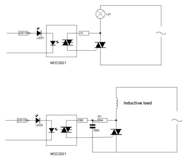
Should you want to use it for inductive loads, then a snubber circuit is necessary. The figure shows the modifications for use with Inductive loads. Mind you, this is not something I tried as I just wanted to dim lamps, but it is based on examples and theory available on the internet. You would have to adapt the provided PCB
The top figure shows the circuit as is, for dimming a lamp. It is in all its simplicity just a resistor to trigger the gate via the diac in the optocoupler. The value of 1k may be changed as discussed in the text before.
The bottom figure gives an omnipresent circuit for use in inductive loads.
It consists of an additional resistor and capacitor. The gate current is below 15mA. If you are using a less sensitive triac to control the inductive load, reduce the resistor from 2.4kΩ to 1.2kΩ, providing more current to drive the triac and increase the capacitor to 200nF. This snubber circuit is there to protect the triac from the high voltage generated from an inductive load. The feedback may cause some problem for non-inductive load. The small leakage can be significant enough to turn on small load (for example a lamp).
There are other snubber circuits, e.g. a resistor and capacitor in series directly over the load
Step 3: The software, a bit of theory
If you could care less about the theory, but just want the software, go to the next step
The way to use an AC dimmer/fader is quite simple once you understand the basics:
In AC the power fed to the lamp is directly related to the total surface of the sinuswave, the lamp can be regulated by only allowing a predictable part of that sinuswave to flow through the lamp.
As such we need a reference point on that sinus from where we calculate when the lamp has to be switched on.
The easiest reference point to use is the so called ‘zero crossing’: the moment that the light goes through zero.
After each zero crossing there is one full half of the sinuswave available to send through the lamp.
So what the software needs to do is to detect the zerocrossing, and then wait for a set amount of time on that sinuswave to switch on the TRIAC.
There are 2 major net frequencies in the world: 100Hz in Europe and most of Asia and Africa and 120 Hz in the America’s (and parts of the Caribean). There are 2 major voltages in the world: 110-120V and 220-240V but they are not important for the mathematics here.
For ease of use I will take the 50Hz frequency as an example:
50Hz is 50 waves per second.
Each sinuswave thus takes 1000ms/50=20ms (miliseconds)
As there are 2 sinuspeaks in a wave that means that after every zero detection there is a 10ms period that we can regulate.
Should we ignite the lamp directly at the beginning of that period, the lamp will receive full power, should we do it at the end of that 10ms period the lamp will receive no ower and should we do it halfway, the lamp will receive half power.
As we are using TRIACs, what the software needs to do is to wait for the zero point at the sinuscurve, take note of that and then wait a specified amount of time within that 10ms period to send a pulse to the TRIAC.
If it sends that pulse at 5ms, the lamp will only burn at half power.
In the Circuit, the zero detection is done by the biphase optocoupler and is available as the X-signal on the board.
There are basically 2 ways for a microcontroller to detect that signal:
1-a continuous ‘polling’ of the Zero Crossing pin
2-using an interrupt to tell the program that there was a zero crossing
The main difference between the two is that in ‘polling’ everytime the computer goes through it’s main loop it needs to check the pin. If your program is busy doing a lot of other things, it might be too late in checking the zero crossing pin, while when using an interrupt, it does not matter what the program is busy with. The interrupt is sort of ‘tapping it on the shoulder’ saying “Hey look, something came up that you need to attend to NOW”.
After the zero crossing is detected the program needs to wait for a specified amount of time and then switch on the TRIAC.
Also here, that waiting can be done in two different ways
1- by issuing a ‘wait’ command
2-by using a timer interrupt
Again, both these methods have their pro’s and con’s. The ‘wait’ command (‘delay’ in Arduino language) literally let’s the computer wait for the required time and it cant do anything else in the mean time. if the lamp is burning at low power by letting the computer wait say 9ms, that means that every 10ms the computer is told to wait 9ms: ergo it will be idle 90% of the time. That is fine if your controller is only used to control the lamp, but if it needs to do other stuff then little time is left.
Using a timer interrupt solves that. Basically what that does is that the program tells the timer: ¨Hey, I just heard we have a zero crossing, I got to do something else, but you just wait 4.5ms and then switch on the Triac” So the program goes on it’s merry way and 4.5ms (as an example) after it was given notice there was a 0-crossing, the timer switches on the TRIAC.
Polling: (note this is a rough example for illustration of polling, obviously it needs some enhancement)
int AC_LOAD=3; //   We use pin 3 to ignite the TRIAC
int state; // integer to store the status of the zero crossing

void setup()
{
pinMode(AC_LOAD, OUTPUT);// Set AC Load pin as output
}

void loop()
{
state=digitalRead(AC_LOAD);
if (state=1) {
delayMicroseconds(5000); // =5 ms=half power
digitalWrite(AC_LOAD, HIGH);   // triac firing
}
Interrupt driven:
To use an interrupt, first we need to set that up. On the Arduino that is as follows:
void setup()
{
  pinMode(AC_LOAD, OUTPUT);// Set AC Load pin as output
  attachInterrupt(0, zero_crosss_int, RISING);  // Choose the zero cross interrupt # from the table above
}
What this says is that the interrupt is attached to interrupt 0, it goes to a function called “zero_crosss_int” and it reacts to a rising flank on the pin.
In the Zero_cross_int function that the program jumps to after the interrupt we determine the time we need to wait before firing the TRIAC. We will also add a bit of functionality. We don’t just want one level set that the lamp burns on, we are going to add some functionality to regulate the light level in steps.
For that I have chosen the fully arbitrary amount of 128 steps. That means that every step is 10ms/128 = 10000us/128=75us (in fact it is 78, but I get to that later). The total dimtime then is calculated from 75x(1 to 128). The number between 1-128, which determines our level of dimming, we assign to the variable integer ‘dimming’
void zero_crosss_int()  // function to be fired at the zero crossing to dim the light
{
  int dimtime = (75*dimming);    // For 60Hz =>65
  delayMicroseconds(dimtime);    // Off cycle
  digitalWrite(AC_LOAD, HIGH);   // triac firing
  delayMicroseconds(10);         // triac On propagation delay (for 60Hz use 8.33)
  digitalWrite(AC_LOAD, LOW);    // triac Off
}
What happens here is that the program first calculates the dimtime (=time to wait before the triac is fired)
It then waits that amount of time, subsequently waits that amount of time and fires the Triac. The Triac will switch off again at the following zero crossing, but we are going to already write a low on the TRIAC pin to avoid accidental ignition in the next cycle. We need to wait a bit however to know for sure the TRIAC is on, so we wait 10us. Now (10000-10)/128 is still 87 but i found 75 to work well. Feel free to use 78 though.
The only thing then left to do in the main program is to set the level at which we want the lamp to burn:
void loop()  {
  for (int i=5; i <= 128; i++){
    dimming=i;
    delay(10);
   }
What happens here is a simple loop that regulates the lamp up in a 128 steps. I have chosen not to start at 1 but at 5 because at that level there could be some timing issues that could cause the lamp to flicker.
The above program is only an example of how to control the lamp, obviously you want to add some other functionality rather than just have a lamp go up and down in brightness.
Using a timer:
If you want your program to be time efficient you will need to use an interrupt for the zero-crossing detection and a timer to determine the amount of time to wait.
Roughly a program would look as follows:
Initialize
Set up the various constants and variables you need and include the libraries used (such as the TimerOne Library)
Setup
Setp the pins and the 2 interrupts
The zero-crosssing interrupt points to a function and so does the timer interrupt
Zero-cross functie
Set a boolean indicating if a zero cross has occurred
Timer function
If we regulate the brightness again in 128 steps, then the timer function is set up to be called whenever the time of a step has passed (e.g. 75us) and then checks if the number of steps passed is equal to the number of steps set. If that is the case, the Triac is switched on
Step 4: Arduino controlled light dimmer: The software
As discussed in the previous theoretical page, the software is fairly easy.
If you want to develop your own software all you need to do is:
Wait for the zerocrossing
Wait a specific time between 0 and 9090 microseconds (9090=10.000-10)
switch on yr TRIAC
Wait for about 10us (that is the time you need to make sure the TRIAC is on)
switch off yr TRIAC (in fact, you only remove the triggersignal to the TRIAC, the TRIAC will stay on till the next zerocrossing)
I just briefly sketch the flow of the program that I used:
(make sure you read the ‘NOTE’ below)
The zero X-ing signal generates an interrupt.
At 50Hz that interrupt is every 10ms or 10.000uS
At 60Hz that interrupt is every 8.333 ms or 8333 uS
The interrupt routine then switches on the Triac after a specific time. That time is set in the main program loop.
As the program varies the dimming from Full to Off in 128 steps (that is just a choice that was made, could be 100 steps as well), at 50 Hz we need the steps to be 75 uS and at 60Hz they need to be 65 uS
It works as follows:
The interrupt function”zero_crosss_int” gets called every time a zero-crossing is detected, which is 100times/second. It’s only function is to set the time that the Triac is switched on to the value of the variable ‘dimming’
In the main loop of the program the actual value of that variable is set
/*

AC Voltage dimmer with Zero cross detection
Author: Charith Fernanado <a href="http://www.inmojo.com"> http://www.inmojo.com
</a>
Adapted by DIY_bloke
License: Creative Commons Attribution Share-Alike 3.0 License.
Attach the Zero cross pin of the module to Arduino External Interrupt pin
Select the correct Interrupt # from the below table
(the Pin numbers are digital pins, NOT physical pins:
digital pin 2 [INT0]=physical pin 4 and digital pin 3 [INT1]= physical pin 5)
check: <a href="http://arduino.cc/en/Reference/attachInterrupt"> http://www.inmojo.com
</a>

Pin    |  Interrrupt # | Arduino Platform
---------------------------------------
2      |  0            |  All -But it is INT1 on the Leonardo
3      |  1            |  All -But it is INT0 on the Leonardo
18     |  5            |  Arduino Mega Only
19     |  4            |  Arduino Mega Only
20     |  3            |  Arduino Mega Only
21     |  2            |  Arduino Mega Only
0      |  0            |  Leonardo
1      |  3            |  Leonardo
7      |  4            |  Leonardo
The Arduino Due has no standard interrupt pins as an iterrupt can be attached to almosty any pin.

In the program pin 2 is chosen
*/
int AC_LOAD = 3;    // Output to Opto Triac pin
int dimming = 128;  // Dimming level (0-128)  0 = ON, 128 = OFF

void setup()
{
  pinMode(AC_LOAD, OUTPUT);// Set AC Load pin as output
  attachInterrupt(0, zero_crosss_int, RISING);  // Choose the zero cross interrupt # from the table above
}

//the interrupt function must take no parameters and return nothing
void zero_crosss_int()  //function to be fired at the zero crossing to dim the light
{
  // Firing angle calculation : 1 full 50Hz wave =1/50=20ms
  // Every zerocrossing thus: (50Hz)-> 10ms (1/2 Cycle)
  // For 60Hz => 8.33ms (10.000/120)
  // 10ms=10000us
  // (10000us - 10us) / 128 = 75 (Approx) For 60Hz =>65

  int dimtime = (75*dimming);    // For 60Hz =>65
  delayMicroseconds(dimtime);    // Wait till firing the TRIAC
  digitalWrite(AC_LOAD, HIGH);   // Fire the TRIAC
  delayMicroseconds(10);         // triac On propogation delay (for 60Hz use 8.33)
  digitalWrite(AC_LOAD, LOW);    // No longer trigger the TRIAC (the next zero crossing will swith it off) TRIAC
}

void loop()  {
  for (int i=5; i <= 128; i++){
    dimming=i;
    delay(10);
   }
}
About the software: theoretically in the loop you could let variable ‘i’ start from ‘0’. However, since the timing in the interrupt is a bit of an approximation using ‘0’ (fully on) could screw up the timing a bit. the same goes for 128 (Full off) though that seems to be less critical. Wether ‘5’ or perhaps ‘1’ is the limit for your set up is a matter of trying, your range may go from e.g. 2 to 126 instead of 0-128. If anybody has a more precise way to set up the timing in the interrupt I’d be happy to hear it.
Ofcourse it is not necessary to work with interrupts. It is also possible to keep polling the zero crossing pin for going to 0.
Though the software works with an interrupt to determine the moment of zero crosssing, it is still not so efficient because the time (dimtime) we need to wait after the zero crossing before the triac is fired is literally spent ‘waiting’ in the zero cross interrupt function.
It would be more efficient to set a timer interrupt to fire at the right moment so in the mean time the arduino can do something else. Such a program can be found in step
NOTE
Let me just reiterate the above statement: This program is a demo of how you can control the dimmer. It is NOT and efficient program as it spends most of its time waiting. It is therefore NOT the most suitable to combine with other tasks of the processor. If you need a more efficient program use a timer instead of delay
Step 5: Arduino Controlled Lightdimmer: The Software II
I found another piece of Software that allows controlling the lamp via the serial port. I have not tested it myself yet, but I see no reason why it should not work. It triggers on the falling edge of the zero-crossing signal, so the timing is a bit different.
int AC_pin = 3;//Pin to OptoTriac
byte dim = 0; //Initial brightness level from 0 to 255, change as you like!

void setup() {
  Serial.begin(9600);
  pinMode(AC_pin, OUTPUT);
  attachInterrupt(0, light, FALLING);//When arduino Pin 2 is FALLING from HIGH to LOW, run light procedure!
}

void light() {
  if (Serial.available()) {
    dim = Serial.read();
    if (dim < 1) {
      //Turn TRIAC completely OFF if dim is 0
      digitalWrite(AC_pin, LOW);
    }

    if (dim > 254) { //Turn TRIAC completely ON if dim is 255
      digitalWrite(AC_pin, HIGH);
    }
  }

  if (dim > 0 && dim < 255) {
    //Dimming part, if dim is not 0 and not 255
    delayMicroseconds(34*(255-dim));
    digitalWrite(AC_pin, HIGH);
    delayMicroseconds(500);
    digitalWrite(AC_pin, LOW);
  }
}
void loop() {
}


Even more software <a href="http://wiki.dxarts.washington.edu/groups/general/wiki/4dd69/AC_Dimmer_Circuit.html" rel="nofollow">here</a>


 If you don’t want the power save feature, replace D3 with a wire link and omit R2,R3,R5,Q2 and Q3.