Quantcast
Channel: LED Projects - PIC Microcontroller
Viewing all 387 articles
Browse latest View live

Easy Way to Design an Automatic Driverless Train

$
0
0

Every one in the metro cities like Kolkata, Delhi enjoying the luxuries of the metro train ever spared a thought about the train? No, then let me give you a brief idea about the driverless automatic driven and controlled train. But before that let us have a brief recall about types of metro automation.

The Driver Controlled Mode:

In conventional modes, it’s the manual driver who drives the train and controls the train motion using the stationary light signals.

Easy Way to Design an Automatic Driverless Train

The Partially Automatic Mode:

In this mode, the driver drives the train while an external control system is used to constantly monitor the speed and acceleration of the train and provide required feedback to the driver.

Driverless Mode:

The whole operation and maintenance of the train is done automatically without any human intervention. The train stops and starts automatically and the doors are closed and opened automatically.

So, now let us fix our attention to the last mode i.e. The Driverless Mode

In a fully automatic driverless train, the control is done through a Communication based train control where a trackside computer is used to monitor the train running on the assigned line and convey this information to the centralized computer. The train is controlled by the automatic train control system.

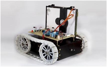
Designing a Basic Prototype of a Automatic Driverless Train

The design will include the following components:

  • A rectangular body which holds all the other robotic components like the control circuit, the door etc.
  • A sliding door prototype
  • A couple of IR LED and photodiode arrangement
  • A control circuitry using a Microcontroller

Working of the Basic Prototype:

So let us see how our basic prototype works does:

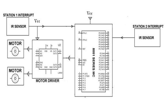
  • The Automatic platform sensing and Door control system: It consists of an IR LED and a photodiode system. When the sensor senses the coming of the station, the motor driver automatically drives the motor such that the train comes to a halt and the door is opened when a person is sensed.
  • Passenger counter system: The train is also equipped with a passenger counter system which counts the number of passengers entering the train and when the count reaches a certain limit the door is closed automatically and the train will start moving after a certain time limit.

Easy Way to Design an Automatic Driverless Train Schematic

How to controls the Train Prototype:

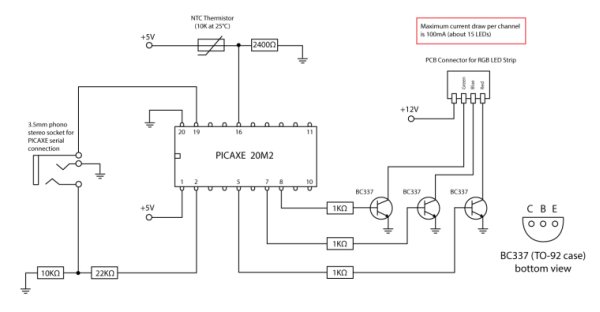
  • Controlling the movement of the train: Normally when the train is moving, the IR LED-photodiode arrangement is placed such that both are placed parallel to each other and thus as the photodiode doesn’t gets the light pulses, it doesn’t conducts and as a result the microcontroller will get a high signal. Now as the train approaches a station, the IR light from the IR LED gets reflected by any object (suppose the station signal) and the reflected light falls on the photodiode, causing it to conduct and thus an interrupt low signal is given to the microcontroller through the transistor. The microcontroller is programmed so as to send signals to the motor driver to stop the motors. The operation of the motor is driven by the motor drive IC; here two stations are connected to the microcontroller through the motor drive.


For more detail: Easy Way to Design an Automatic Driverless Train

The post Easy Way to Design an Automatic Driverless Train appeared first on PIC Microcontroller.


Cheap PIC Programmer

$
0
0

This programmer works only with PIC16F84 but it’s great because it never causes errors and works with almost all computers,unlike some other homemade programmers.

Step 1: Step one : Materials

For this programmer you won’t need many materials.In fact , you will find all you need in your local electronics shop 😉

So here’s what materials you will need:
-IC Board
-RS232(Serial) FEMALE connector
-BC547B or 2N3904 (I couldn’t find the BC so i used 2N3904,it works great)
-5.1 V diode
-100 uF 16V Electrolytic Capacitor

Cheap PIC Programmer
-18 PIN IC Socket
-10Kohm resistor
-15Kohm resistor
OPTIONAL[
-Flashing red LED / 2.1 V Standard Red LED
-3.3Kohm Resistor]
-PIC16F84A Microcontroller
Tools:
-Soldering Iron
-Scissors or any other cuting tool

OPTIONAL[
-Hot glue gun]

Step 2: Step two : The scheme

This is the scheme you will use for your programmer.
As you can see , i tagged two connection in the scheme as “Optional point” one and two .
Those are the points where you will connect the “Optional” circuit i will show you in step 3

Step 3: Step three : The optional circuit

The optional circuit consists of the LED and 3.3 Kohm resistor marked as optional in step one.
One pin of the resistor goes in the Optional point one , the other pin goes in the anode(+) of the LED.
The cathone(-) pin of the LED will go in Optional point two.
If you don’t understand , use the ellipse marked area of the scheme below.

Cheap PIC Programmer Schematic

Step 4: Step four : Let’s build it !

Ok , you’ve got all you need.Now it’s time to build it.
DON’T CUT THE IC BOARD YET!
First solder the RS232 female connector in a corner of your IC Board.If you don’t know what are the connectors of the RS232 i uploaded an image.
After you soldered the RS232 , solder all elements according to the schematic,and then cut the board.
After you cut the board,secure all solderings with hot glue (optional).
You’re done!


For more detail: Cheap PIC Programmer

The post Cheap PIC Programmer appeared first on PIC Microcontroller.

RGB REMOTE (pinguino+web+linksys) using PIC18F2550 microcontroller

$
0
0

RGB REMOTE (pinguino+web+linksys)

This project has several uses, it is basically a way to control an RGB LED group (tricolor with common ground) via a web page to select which color we want to show.

RGB REMOTE
It may be a way to harmonize a room, change the color of a swimming pool or just fooling aroun

Step 1

RGB REMOTE webserver and serial connection

RGB REMOTE webserver and serial connection

In my case the web server is in Linksys router which I have “hacked / tunner” and installed a version of Linux opensource … in this case OpenWRT 9.02, with this special version for this type of equipment, It can be more flexible than the original software. Installing LUA and one webserver and I have all that I will need.

As to the little memory space of this team, to host my website, I have included a change and I have installed a 1GB SD card as hard drive so you can play and install things without fear to occupy the 5Mb which has by default. I’ve also created two output interfaces for internal serial ports by default has LINKSYS and that, in principle are control consoles, modifying a bit its used to connect any computer with RS232 communication.

Step 2

RGB REMOTE pinguino

I use a hardware interface with the 18F2550 microcontroller PINGUINO PIC Firmware v2, 12. This has a basic programming, which attempts to transfer via serial communication from the web server and has scripts that send orders and data via serial port. For example by sending the character “R” means to tell the microcontroller that the LEDs turn RED ONLY. And so with all the colors and combinations.

link original http://www.hackinglab.org/pinguino/index_pinguino.html
link Madrid http://pinguino.walii.es

The program basically tells the microcontroller that the serial port and listen when you get status R eg send a pulse to continuous 5volts particular output for the red LEDs. And finally sent to the serial port the color name that is kindled.
The code is as follows. USE PINGUINO GUI to programate it.
// Prueba de Puerto serie comandando RGB

// walii.es 2010

//aquí agregamos las posibles variables.

int i; //para nuestro contador de puertos

int key; //para la tecla que escucha por el Puerto serie.

void setup()

{

//Aquí configuramos los puertos de salida para que inicien

//en estado de SALIDA y APAGADOs.

for (i=1;i<4;i++){

pinMode(i,OUTPUT);

digitalWrite(i,LOW);

}

//Aquí configuramos el Puerto serie, para que escuche peticiones a 9600bps,

//suficiente para este proyecto.

Serial.begin(9600);

}

//Y por acá podemos ver la configuración de comandos a escuchar en el Puerto

//serie y hacer lo necesario para iniciar los leds que correspondan a la acción

void loop()

{

if Serial.available()

{

key=Serial.read(); //escucha el Puerto serie…

if (key==’r’) digitalWrite(1,1),digitalWrite(2,0),digitalWrite(3,0),Serial.print(“rojo”);

if (key==’v’) digitalWrite(1,0),digitalWrite(2,1),digitalWrite(3,0),Serial.print(“verde”);

if (key==’a’) digitalWrite(1,0),digitalWrite(2,0),digitalWrite(3,1),Serial.print(“azul”);

if (key==’m’) digitalWrite(1,1),digitalWrite(2,1),digitalWrite(3,0),Serial.print(“marron”);

if (key==’b’) digitalWrite(1,1),digitalWrite(2,0),digitalWrite(3,1),Serial.print(“morado”);

if (key==’n’) digitalWrite(1,0),digitalWrite(2,1),digitalWrite(3,1),Serial.print(“celeste”);

if (key==’w’) digitalWrite(1,1),digitalWrite(2,1),digitalWrite(3,1),Serial.print(“blanco”);

if (key==’c’) digitalWrite(1,0),digitalWrite(2,0),digitalWrite(3,0),Serial.print(“apagado”);

Serial.print(“\n\r”); //por ultimo imprimimos el nombre del color seleccionado.

}

//vuelve a comenzar el loop

}

For more detail: RGB REMOTE (pinguino+web+linksys) using PIC18F2550 microcontroller

The post RGB REMOTE (pinguino+web+linksys) using PIC18F2550 microcontroller appeared first on PIC Microcontroller.

Knight Rider Light computer – version 2

$
0
0

This knight rider light computer is a successor of my first version of the Knight Rider. This version is much smaller and justifies the use of a microcontroller. The project is based on the PIC 12F629 microcontroller.

The hardware part

Unlike my previous project this light computer is build around the PIC12F629: a microcontroller with only 8 pins. It is shipped in a DIL-8 housing.

Knight Rider Light computer - version 2An external clock is not necessary: the chip has an internal 4 MHz oscillator. The reset circuit is not necessary either: I configured the PIC to use its internal reset circuit. So only 2 pins are needed to power the microcontroller. All other pins are available for I/O.

The schematic diagram can be kept very small. You only need the PIC12F629, eight LEDs, two resistors and a zenerdiode.

Each output of the PIC drives two LEDs. The cathode of all LEDs is common and connected to a single resistor. This is not a good design practice: each LED should have its own resistors as LEDs should never be placed in parallel. I did it anyway in this particular design because I needed a very compact solution (2 LEDs of the same type can slightly differ: they can have a different forward voltage. This can cause problems when they are placed in parallel).

The PIC’s GP03 port doesn’t drive any LEDs because it is solely an input port.

The circuit itself must be powered by a 9 VDC supply. This voltage is down sized to 4.7V by a zenerdiode D1 and resistor R2. Eventually they can be replaced by a 7805 regulator.

Possible PCB Layout

The image at the left illustrates how small this circuit could be when you create a PCB of it.Please note I drew this PCB very quick – I didn’t check it for errors as it is just an example. The PCB can’t be downloaded from this website.

Knight Rider Light computer - version 2 SchematicThe software part

I wrote the software in the C language. I used the (free) HI-TECH C language that was included with MPLab, a tool for the PIC microprocessors.

I used an array that contains all the 6 different output states. A loop is cycled: each cycle another output state is retrieved from the array.

I programmed this microcontroller with my very cheap Olimex USB PIC programmer [External]. This programmer can be used with Microchip MPLab so you don’t need any additional software.


For more detail: Knight Rider Light computer – version 2

The post Knight Rider Light computer – version 2 appeared first on PIC Microcontroller.

Pimp My Rocket (Espresso Machine)

$
0
0

Combining Coffee and Electronics – An Idea for a Project

Having played around with fixed function logic ICs, such as the Johnson counter used in the Spindicator project, I was keen to move on and experiment with programmable microcontrollers. I decided to obtain and play with some PICAXE chips, as they looked like they would provide an easy introduction to using microcontrollers. Soon enough I was flashing LEDs and building touch-activated computer power switches. But what I really wanted to try was using the chip to control the colour of an RGB LED. For a suitable project I came up with the idea of using a strip of RGB LEDs to provide accent lighting for my Rocket Espresso coffee machine, where the colour of the LED would depend on the temperature of the machine (specifically the inlet water to the brew head). I thought this had the potential to not only look pretty, but actually provide useful visual feedback on the all important brew water temperature. If you are reading this because you’re a coffee geek interested in E61 HX type espresso machines, you may want to skip the electronics part and read the last section to see how it turned out.

PICAXE is a low-cost, easy to use microcontroller system which uses a simple BASIC like programming language. I’m not going to provide a tutorial on how to use and program PICAXE chips in this post. If you are interested in that, the PICAXE website has excellent documentation, free programming software, and lots of circuit and code examples. There are several different PICAXE chips you can buy, with different numbers of inputs/outputs and different inbuilt functionality. The inbuilt PICAXE function that is central to this project is PWM (pulse-width modulation).

Pimp My Rocket (Espresso Machine)Controlling RGB LED Colour with PWM

An RGB LED is actually made of three LEDs under one lens, a red, blue and green LED (I’ll call these sub-LEDs). Each sub-LED can be switched on separately, so you can switch on blue and red to get purple for example. By switching each sub-LED completely on or off  you can make six colours (red, blue, green, purple, cyan and yellow). In order to gain access to a complete spectrum of colours, you need to be able to precisely control the brightness of each sub-LED, and the way to easily do that is via pulse-width modulation. PWM controls the brightness of an LED by switching it on and off very fast (20,ooo  times per second in my program), and controlling the amount of time it is on during each on-off cycle. The time for an on-off cycle is called the period (50µs in this case), and the time of the on pulse as a percentage of the period is called the duty cycle. So a for duty cycle of 50% at 20kHz, the LED will be switched on for 25µs, then off for 25µs. The switching is too fast for the eye to see, and so the overall result is that the LED will just look half as bright. Thus the LED brightness is directly proportional to the duty cycle. Most PICAXE microcontrollers have a PWM control function built in and accessible on one or more of the chip’s pins (see pinout diagrams in the PICAXE manual). Some PICAXE chips also have separate PWM control circuitry referred to as “HPWM”, or hardware PWM. The circuit and program described below uses the software PWM function. To control an RGB LED you need a chip with three (or more) independent PWM outputs such as the 14M2 or the 20M2. For this project I used the 20M2.

The Circuit

The circuit for this project is fairly simple as the PICAXE microcontroller does most of the work. For the LEDs I used a strip of six RGB LEDs. These  are pre-wired to a strip of adhesive backed flexible circuit board as shown in the photo above. They come on a long roll which can be cut to any multiple of three LEDs. Initially I was going to use two sets of six, one mounted under the Rocket on each side. Consequently, this circuit is designed to drive 12 LEDs, and can drive up to 15 using the transistors and resistors specified. When I tried it though, I didn’t like the look of the reflections of the individual LEDs off the stainless steel bench on which my machine sits. In the end I decided to use one strip of six mounted behind the machine and reflecting a nice diffused colour off the wall behind. The first circuit diagram below shows the power supply for the PICAXE and LEDs. The 12 volt DC input is supplied from a small 500 mA 12V plug-in power adaptor. This 12V input is used directly as the power supply for the LEDs, and also as the input to a 7805 voltage regulator with 5V output. The 5V rail powers the PICAXE chip and peripheral circuitry. I added a small LED to the 5V output as visual confirmation of PICAXE power on. The switch on the 12V input is to assist with programming the PICAXE (the best way to program the chip is to initiate transfer from the computer with the power off, then quickly switch the power on). To save space I implemented this switch with a simple two pin header and jumper, which is actually a bit fiddly. If I were to build it again I would use a proper PCB-mounted mini toggle switch.

The rest of the circuit is shown in the diagram below. It can be divided into four parts; the 20M2 PICAXE chip itself, the serial programming interface circuit, the thermistor voltage divider and the LED switching transistors.

The serial interface part of the circuit consists of two resistors and a 3.5mm stereo phono jack,  and is the standard minimum serial communication circuit as specified in the PICAXE literature. This can be used with either a simple serial cable (for connecting to a computer serial port, if your computer still has one), or the PICAXE USB  cable. For a temperature sensor I used a standard 10KOhm NTC thermistor (a component whose resistance changes in response to temperature). The thermistor forms half of a voltage divider with a 2.4K resistor, the divided voltage being read by the PICAXE analog to digital conversion function (ADC). The value of 2.4K was chosen to give a reasonably linear relationship between the divider voltage and thermistor temperature over the range of interest (25 to 120°C), as well as the greatest change in voltage over this range. This relationship can be calculated, and is shown in the plot below for my thermistor, which has a specified calibration constant (beta) of 4,100K.

The PICAXE ADC function converts the voltage at the input pin to a number between 0 and 255  in direct proportion to the voltage. This number is then used by the program to calculate and adjust the duty cycle of each sub-LED (red, blue and green). Because the LED strip requires a supply voltage of 12V, and because a PICAXE output can only sink or source up to 20mA, the LEDs are switched via three BC337 transistors (for my final 6-LED configuration, I could have also used BC548 transistors with say a 2KOhm base resistor). For the particular RGB LED strip I used, I measured the 100% duty cycle current per sub-LED at 6.2mA (red), 5.5mA (green) and 5.7mA (blue). Thus for a strip of six LEDs, the maximum current that any transistor will switch is 37mA. In the circuit shown above, the BC337’s can switch 100mA and remain saturated (probably more, but that’s a safe figure), which means that the circuit will safely switch a strip of 15 LEDs (they come in multiples of 3 remember). By reducing the base resistor value you could switch a lot more LEDs, as BC337’s have a maximum collector current of 800mA (you may need a gruntier 12V supply than I’ve specified though, and don’t forget the PICAXE per-output 20mA maximum current, with 90mA maximum per chip).

Pimp My Rocket (Espresso Machine) SchematicAfter going to some trouble to design a PCB layout in Illustrator, I decided that I couldn’t be bothered trying to etch a circuit board, so I made up the circuit using a prototype board and jumper wires, with screw terminals to connect the power supply, thermistor and LED strip. The board is illustrated below.

The rest of the circuit is shown in the diagram below. It can be divided into four parts; the 20M2 PICAXE chip itself, the serial programming interface circuit, the thermistor voltage divider and the LED switching transistors. The serial interface part of the circuit consists of two resistors and a 3.5mm stereo phono jack,  and is the standard minimum serial communication circuit as specified in the PICAXE literature. This can be used with either a simple serial cable (for connecting to a computer serial port, if your computer still has one), or the PICAXE USB  cable. For a temperature sensor I used a standard 10KOhm NTC thermistor (a component whose resistance changes in response to temperature). The thermistor forms half of a voltage divider with a 2.4K resistor, the divided voltage being read by the PICAXE analog to digital conversion function (ADC). The value of 2.4K was chosen to give a reasonably linear relationship between the divider voltage and thermistor temperature over the range of interest (25 to 120°C), as well as the greatest change in voltage over this range. This relationship can be calculated, and is shown in the plot below for my thermistor, which has a specified calibration constant (beta) of 4,100K.


For more detail: Pimp My Rocket (Espresso Machine)

Current Project / Post can also be found using:

  • how to play matrix led with pic in proteus

The post Pimp My Rocket (Espresso Machine) appeared first on PIC Microcontroller.

Text in the air with PIC16F84

$
0
0

Writing LEDs air

Today, most electronic systems with complex functions, micro-controllers are designed using. Easily programlanabilmeleri, prices to be cheaper and less due to external hardware requirements microcontrollers have an important place in the field of electronics. For example, Series produced by the company Microchip PIC microcontrollers, is one of the most preferred in the market of integrated, programmable. Bu entegreler 8, 18, 28 or 40 produced, many types of legs.

16F8X series of these PIC microcontrollers, 18 and flash memory technology has legs. Thanks to this technology, and can be removed easily integrated to integrated re-installed program can be programmed at any time. 13 One input-output port (Port A Port B ve) Not enough for most applications. Integrated in assembly language for programming, as well as high-level languages ​​such as BASIC or C can also be used. PIC microcontrollers are many books on the market. Detailed information can be learned from these books [1].

Text in the air with PIC16F84In this article,, From PIC16F84A microcontroller and 8 writing up the construction of an electronic circuit using LEDs is described. With this circuit 8-10 of characters that can be created with any text in the air.

Circuit diagram

Circuit diagram as shown in Figure 1 PIC16F84A micro-controller port B outputs 8 number LED and resistors connected. 422pF’lık MHz crystal and oscillator circuit consisting of two condenser produces clock pulses required for the operation of the PIC. Supply circuit is provided with a 9V battery and a 5V regulator circuit.

Required materials

  • 1 One PIC16F84A microcontroller
  • 1 One LM7805 voltage regulator
  • 1 took 4MHz crystal
  • 1 adet buton
  • 1 One key
  • 1 aThe 100nF kondansatör
  • 2 aThe 22pF kondansatör
  • 1 adet 4.7k direnç
  • 1 adet 1N4148 diyot
  • 8 ADET Parlak Mavi LED
  • 8 number 100 ohm direnç
  • 1 One 9V battery, and the battery cap
  • Copper plate or perforated phenolic

The logic is

Operation of the circuit is based on the principle of illusion. As we know, the eye, recognizes and repeats periodically repeated events, such as the time between durağanmış short enough not to realize the impact of the flicker. For example 1 second 50 A flashing light on fire, gives the impression of a continuous time. Likewise television motion of the picture of the frame repetition frequency is selected high enough continuously detected. Feature of the error of the eye, LED provides up into the air with a few pieces of writing.

Equipped electronic circuit shown in Figure 1, although a fairly simple circuit must be installed in order to run a program the PIC microcontroller. The job of the loaded program, based on the characters printed on the air 8 One LED is lit and put out all about setting a schedule. After you install the program correctly PIC LEDs quickly moved to the right-to-left text is provided in the air the formation of. Briefly, The logic of operation of the system, Sent to the PIC 8 at which time the LED stays on with columns of bits which can be summarized as set.

Before writing the program to write letters in the air (or character) need to be made through the column by. To do this, I need to make a few drawings on paper. For example in figure 2, A, B, C to form letters 8 Depending on the time step should be lit LEDs showing which.

Each letter is illustrated in, 8 rows and 5 consists of columns. Letters between 1 column is empty. According to this logic into the air 8 writing letters to a total of 48 pieces of information needed by the column. So the PIC microcontroller 48 One column information in time

intervals must be programmed to send port.

Text in the air with PIC16F84 SchematicFigure 3 shows in detail how the information is obtained from the column. For example, a letter needs to be done to get the column information, Instead of off-state LEDs 0 figure, LEDs are lit as a substitute for 1 figure consists of writing. In this case, for each column 0 and consisting of 1s 8 bit number is obtained.

This number of 16 (hexadesimal) data is written to the base column is obtained. For example, the letter A in the first column 8 bit 11111100 0xFC’dir for the base number of 16. In the same way in the last column 00000000 for the base number of 16 is 00 or 0 ×. Here, at the base 0x symbol indicates that the number of 16. In this way, information can be easily obtained all the letters column for.


For more detail: Text in the air with PIC16F84

Current Project / Post can also be found using:

  • projects for LED using micro controller
  • simple led projects

The post Text in the air with PIC16F84 appeared first on PIC Microcontroller.

Navigation Lights for Models for PIC12F629

$
0
0

Description

This project was inspired from a post on the Picprojects forum where a member had adapted the RGB Moodlight project for use as a strobe and beacon for a model aircraft.

I thought this would be of interest to others so I’ve put this page together with schematic, examples and free code download.  You can also buy a PIC pre-programmed with the firmware from the Picprojects e-Shop

The sequence data has been custom written to produce the beacon and strobe light effects found on aircraft and boats.

The design has been kept as simple as possible to keep the size small and therefore easy to build into a model.  The circuit has very low power consumption and can be powered from Alkaline or rechargeable batteries.

It is not necessary to use all the outputs, for example the beacon output is also very effective for use in a model Lighthouse.

For those with access to a PIC programmer the source code is available to allow you to customise the sequences and program the PIC with your own effects.

Navigation Lights

Circuit Description

The circuit use a PIC microcontroller, IC1, to drive LEDs with a pulse width modulated (PWM) signal that allows the brightness of each LED to be controlled and faded

There are a number of sequences programmed into the PIC and these can be selected by pressing the sequence select switch SW1.  Each time the switch is pressed the next sequence is selected, when the last sequence has been reached it returns to the first.   The selected sequence is saved to non-volatile EEPROM about 10 seconds after the switch is pressed.  On power-up the last saved sequence is used.

There are two versions of this project and two versions of the firmware which can be downloaded at the bottom of the page.

Basic version: all outputs operate continually while powered on.

Servo Controlled Version:  Outputs are activated under control of an RC servo pulse input.  The outputs still perform the same stobe/beacon/position lights when active but can be turned off under control of the servo signal

The servo pulse is monitored on the GPIO4 input of the PIC.  The signal on the PIC input needs to be active low so the NPN transistor Q1, is used to invert the normal servo pulse signal.

When the servo pulse is between:

  • 1ms – 1.25ms all outputs are off
  • 1.25ms – 1.5ms output GPIO2 is active
  • 1.5ms – 1.75ms outputs GPIO2 and GPIO1 are active
  • 1.75ms – 2ms GPIO2, GPIO1 and GPIO0 are active

Outputs

For the Model Navigation Lights project the function of the outputs is predefined.

  • GPIO0 (pin 7) operates as a anti-collision beacon simulating a rotating light.
  • GPIO1 (pin 6) operates as a strobe
  • GPIO2 (pin 5) is driven with a constant 30% duty cycle signal for navigation lights

LEDs on GPIO2 are driven with a 30% duty cycle which reduces overall battery drain and if you want to dig into the source code and alter the sequence data (in the RCnavLightsData.inc file) you can modify the duty cycle to adjust the brightness.  You could can also leave this output unused and just wire the LEDs directly across the battery (not forgetting the current limit resistors!)

The schematic shows one LED attached to each of the GPIO0 and GPIO1 outputs.  You can if required add a second LED to these outputs by using a second resistor and LED as we have done with the navigation LEDs connected to GPIO2.

The resistor values shown on the schematic for the LEDs are 270 ohms.  This will work for almost all types of 3/5/10mm LEDs.  To increase the LED current and brightness (at the expense of battery life) you can use a lower value resistor but don’t go below 150 ohms.

LEDs

For the navigation lights shown we have used red, green and white LEDs but you can use any colour LED you want to suit your project.   The PIC can directly drive (via a current limit resistor) LEDs up to 25mA per output.  Most small 3/5/10mm LEDs will work.  If you want to drive higher power LEDs you can use the firmware for this project with the Power MOSFET RGB LED Driver project

Capacitor C1 and Resistor R5

Capacitor C1 provides power supply decoupling.  It is important this is fitted as close to the power supply pins of IC1 as possible.  Ceramic capacitors come in either disc or multilayer type – multilayer ones are generally smaller but either type will work.

Resistor R5 is used to pull up the MCLR reset input on the Microcontroller.  If it isn’t fitted the circuit will operate erratically or not at all.

Transistor Q1 and Resistor R6

Only used with the servo controlled version.  Q1 inverts the normal active high servo pulse which is required by the PIC microcontroller.  R6 is a 1K0, 0.25w resistor. 

SW1 Switch

Is used to select the sequence effects.  Any small push-to-make type switch should work here. 

Since the last selected sequence is saved, if you are trying to keep the circuit as small as possible you can make a temporary switch connection to set the sequence you require, them remove it before building it in your model.

SW2 Power Switch

Depending on how you use this project you may be powering it from some other power source that already has a power switch.  If not, you will probably want to fit a SPST (single-pole, single thow) slide or toggle switch to allow the circuit to be switched on and off.

Power Supply

The circuit as shown in the schematic draws an average current of around 7mA operating from a 4.5 volt supply.

It can be powered from three 1.5 volt alkaline batteries or four 1.2 volt NiMH rechargeable batteries.   The PIC microcontroller  will operate with a supply voltage from 3 volts to 5 volts but high brightness LEDs will need a minimum supply voltage of 4 volts to operate effectively.   The power supply must not exceed 5 volts otherwise the PIC microcontroller may be permanently damaged.


For more detail: Navigation Lights for Models for PIC12F629

The post Navigation Lights for Models for PIC12F629 appeared first on PIC Microcontroller.

Skateboard with PIC microcontroller and LEDs

$
0
0

What do you get when an Electrical Engineer builds a Skateboard from scratch for a 13 year old’s Christmas present? You get a skateboard with eight white LEDs (headlights), eight red LEDs (tailights) all controlled via PIC microntroller! And I might add, one very happy 13 year old, well as happy as a 13 year old can be. Following is how I modified a skateboard kit (from ROAROCKIT.COM), added LEDs to the front and back, added PIC circuit, and covered with a comic book and custom graphics.

Skateboard with PIC microcontroller and LEDs

Step 1: Start building the Skateboard

Starting with a laminate kit that was purchased from www.roarockit.com, laminate the first three layers together. The laminate kit from roarockit includes everything needed to laminate and form your own skateboard. This is the second kit that I have used from them and have been very happy with their product.
1. Place the first laminate on the foam mold.
2. Spread the skateboard glue on the first layer.
3. Place the second laminate on top of the first.
4. Spread the skateboard glue on the second layer.
5. Place the third laminate on top of the second.
6. Insert guide pin.
7. Slide the assembly into the netting.
8. Slide the assembly into the vacuum bag, seal the bag, and pump out all the air.

Skateboard with PIC microcontroller and LEDs Schemetic

Step 2: Create Channel for Wires

The wires that connect the LEDs at the front and the back of the Skateboard to the circuit board are installed in the fourth (middle) laminate of the skateboard.
1. After 24 hours remove the first three laminates from the vacuum bag.
2. Cut a channel/groove into the fourth laminate.
3. Add glue to the top of the first three laminate.
4. Place the fourth laminate on top of the assemble.
5. Place the assembly onto the foam mold, insert guide pin.
6. Place the entire assembly into the netting, then vacuum bag, and vacuum all the air out again.


For more detail: Skateboard with PIC microcontroller and LEDs

Current Project / Post can also be found using:

  • led RGB blinking of pic microcontroller
  • build rgb led blinking of pic microcontroller
  • microcpntroller based led project
  • pic16f628 led project

The post Skateboard with PIC microcontroller and LEDs appeared first on PIC Microcontroller.


LEDs sync to music (with pics of my awesome computer case mod)

$
0
0

I’m finishing up my computer table i’ve been working on and one of the final touches is making LEDs sync to the speakers.  I have some pics of my computer too.  This project took me about 15 minutes and was free because i had the parts laying around.

LEDs sync to music (with pics of my awesome computer case mod)

Step 1: Materials

 Items:
-TIP31 transistor
-4 LEDs or 12v led strips
-wire
-on/off switch
-3.5mm jacks (1 male and 1 female)
-solder
Tools:
-soldering iron
-wire strippers/cutters

Step 2: Build the circuit

Here is the circuit i used.  For the 12v power supply i found a spare molex connector from the computer power supply and cut it. I used a multi meter to find which 2 was the positive and negative.  (for me the yellow was positive and the black wire beside it was negative).  Be careful when doing this and make sure the computer is off to prevent the risk of electric shock. (im not responsible if you get shocked or hurt).   If you have any questions just comment below.


For more detail: LEDs sync to music (with pics of my awesome computer case mod)

The post LEDs sync to music (with pics of my awesome computer case mod) appeared first on PIC Microcontroller.

PIC16F84A LED blinking code + Proteus simulation

$
0
0

This post provides the code to make an LED blink using PIC16F84A microcontroller. This code is written in C language using MPLAB with HI-TECH C compiler. This code is intended to be the first step in learning how to use PIC16F84A microcontroller in your projects. You can download this code from the ‘Downloads’ section at the bottom of this page.Following figure shows the minimum circuit required to make an LED blink with PIC16F84A.

PIC16F84A LED blinking code + Proteus simulationIn this figure, first thing to note is that there is a crystal of 20MHz used with PIC16F84A[1]. You can use any crystal from 0 to 20MHz with PIC16F84A. MCLR master reset pin is pulled high to keep PIC16F84A out of reset. RA0 pin is being toggled in the code.

microcontrollers, then you have to include “htc.h” file in the code. After including “htc.h” file, configuration bits are being set in the code shown above. To understand the details of how these configuration bits are being programmed, you can read this post.After the configuration bits, LED pin is being defined as the RA0 pin. You can replace RA0 with any other pin name if you want (e-g RB0 etc). After LED pin definition, CPU frequency is being defined.

PIC16F84A LED blinking code + Proteus simulation SchematicYou have to define _XTAL_FREQ macro, if you want to use built in delay functions like __delay_us() and __delay_ms(). Here CPU frequency is defined to be 20MHz, which is the crystal oscillator frequency attached with PIC16F84A in the circuit.In the main function, firstly RA0 pin direction is set to be an output pin using TRISA0 = 0; statement. Using TRISx register[2], we can set the direction of any pin i-e if it is an input or output. Then LED pin is made low using LED = 0;statement.LED pin is being toggled in the while loop after every half second. In this way you can easily make LED blink using PIC16F84A microcontroller.


For more detail: PIC16F84A LED blinking code + Proteus simulation 

The post PIC16F84A LED blinking code + Proteus simulation appeared first on PIC Microcontroller.

PIC 3x3x3 LED cube

$
0
0

Here´s my 3x3x3 LED cube, it’s controlled by a PIC16F628A microcontroller.
This is my first microcontroller project that finally works, so i suppose is not that difficult to make for beginners.

I hope you’ll enjoy that instructable and even make your own LED cube!

Step 1: Materials

The PIC drives the cube without external IC’s and with very few extra components.
To make your own LED cube you’ll need:

-A PIC16F628A Microchip microcontroller ($2 ebay)

PIC 3x3x3 LED cube

-27 diffused LEDs ($3.50 50pcs ebay)

-7805 voltage regulator ($0.99 3pcs ebay)

-9 330ohm resistors ($1.14 ebay)

-12 male + 12 female headers ($2.59 ebay)

-18 pin DIP IC socket ($0.99 10pcs ebay)

-Controller and cube circuit boards (make them yourself)

-16v 100uF electrolytic capacitor (recycled from old boards)

-100nF ceramic capacitor (recycled from old boards)

-Plug and small heatsink (recycled from old boards)

Step 2: The controller

First, make the controller board (instructions here), drill the holes and tin the pads carefully.
Place all the components as shown in the picture and solder them in place.

Step 3: The cube

Mark a 3×3 1 inch grid in a corck and hole the places for the LEDs, this will keep them aligned while you bend and solder the leads.
Place them diagonally so the leads won’t touch, solder the cathodes to one side and then bend the anodes above the cathodes. Solder the anodes 90º away from the cathodes.

PIC 3x3x3 LED cube Schematic

Repeat the process to make two more grids and place them on each other making anodes and cathodes be in the same side.
Bend the 9 protuding cathodes down and solder them in 3 columns.

I’ve bent the 9 anodes so they came arranged in three groups of three, you can simply solder a ribbon cable, but it won’t hold the cube up as a structure.

Use the pictures to guide you.


For more detail: PIC 3x3x3 LED cube

The post PIC 3x3x3 LED cube appeared first on PIC Microcontroller.

Wave JT – Larson Scanner with Joule Thief

$
0
0

I love LED chasers. A bunch of LEDs neatly turning on and off on a precise timing – lights running one way, then the other way… It’s relaxing, soothing, and hypnotic.
There are so many LED chaser/scanner/sequencer circuits out there, some are made with discreet transistors, some based on logic ICs, and more and more others are using microcontrollers.

There is one thing in common with all of the LED chaser circuits you find on the net – none of them can operate with just one alkaline battery!
Most of us know that LEDs need at least 2.2V or so to light. Blue and white LEDs require even higher, typically 3.2V. So obviously you can’t use just one AA battery to operate an LED chaser. But we all know that there is Joule Thief that boosts voltage high enough to light any LEDs. Why not use that to operate an LED chaser?

Missing Link

Joule Thief is a nickname for this simple voltage boost circuit, predominantly used to light LEDs with one battery cell. However Joule Thief can be used to power more than just LEDs. I decided to power a microcontroller circuit with Joule Thief. (Although I ended up still lighting LEDs.)

Wave JT - Larson Scanner with Joule ThiefStep 1: Features

Wave JT is not only powered by a single AA battery, but it’s feature rich. Here are the highlights of the Wave JT.

  • Compact & streamlined design.
  • Uses only one AA battery (or any 1.5V battery you can hook up to).
  • Works well with rechargeables (NiMH or NiCd) too.
  • Eight LEDs, each with its own 256 level brightness control.
  • Energy efficient – works even with a run-down battery, down to 0.6V (0.8V to startup).
  • Versatile PIC microcontroller based LED chaser/scanner/sequencer.
  • Many light animation patterns to choose from.
  • Speed control via multiple taps of a button (double/triple taps to speed up/down).
  • Start up “Quick-select” mode to choose from top 8 of over 16 pat

Step 2: Technical Overview

Brief Background on Joule Thief
“Joule Thief” circuit is an inductor based voltage booster circuit to light LEDs with low supply voltage. The original circuit was published in 1999 and has been quite popular. You can see the principle of the circuit here: http://en.wikipedia.org/wiki/Joule_thief

My version is a variation that uses single coil inductor, to make the inductor easily obtainable. I designed the circuit using readily available parts only, to make it an ideal DIY project.

Why Joule Thief?

There are many options to create 5V from low voltage. First of all, there are many ICs made specifically for this purpose. Those ICs are usually simple to use, and very energy efficient. However they are not cheap – typically a few Dollars a piece.
Compare that with a Joule Thief – two transistors, two resistors, a capacitor and an inductor together is still cheaper than just the IC. Plus you know how the circuit works, instead of just taking a black box someone created. I think this is an important point for Makers.
As it turned out, a simple Joule Thief circuit that I used here is more than adequate for supplying power for microcontroller project. The fact that microcontroller can actively regulate the Joule Thief’s output voltage (more on this later) to improve overall efficiency makes this simple arrangement attractive.

Some Thoughts on Efficiency

I see a lot of discussion made about conversion efficiency of voltage converter circuit (Joule Thief included). No matter how efficient we make the converter, there will be some energy loss. So why use a voltage booster when you can simply use more batteries?
While a simple Joule Thief circuit like the one used with Wave JT does not have very high efficiency in converting voltage, it does allow us to use one battery instead of two or three. The net result is that there will be less batteries consumed because only one battery is used at a time (instead of two or three).

Step 3: Circuit

The power supply (voltage booster) part of schematic shows somewhat typical Joule Thief circuit, plus a few extra parts.
D1 (Schottky diode) and C2 form a rectifier to create DC voltage out of the Joule Thief. Zener diode D2 is added to “clamp” or limit the voltage at 5.1V to prevent damaging the microcontroller (maximum voltage this chip can withstand is 6V). Without the Zener diode there, the output voltage from the boost circuit can go over 6V when no LEDs are lit.
When the battery is first connected, the voltage charges the capacitor C2, then nothing happens until SW1 is closed. Once the SW1 is closed, current goes through R1 to turn on Q2, and the Joule Thief circuit starts working. In a fraction of a second, the voltage at C2 reaches high enough for the microcontroller to start up. Once the microcontroller starts running, it puts PWR signal high, so that the Joule Thief will keep running even after SW1 is open. (Power-on latch)
Note that after initial power up, microcontroller watches its own supply voltage via A/D converter and adjusts it slightly below the zener voltage, so to not waste precious power from the battery. “PWR” connection to the microprocessor does this by turning on/off bias current to Q2.
This “PWR” pin has two purpose; one is to control the booster circuit, the other is to read the status of the button switch. (this arrangement saves a precious microcontroller pin.)

Wave JT - Larson Scanner with Joule Thief SchematicThe button switch SW1 is more than a power switch, it provides pattern change, animation speed change (double tap to increase the speed, triple tap to decrease the speed). Microcontroller reads the button state by periodically turning the “PWR” pin into an input pin. This happens roughly every 8 milliseconds (125 times/second). The reading of the button takes about 2 microseconds each. The booster circuit turns off during this 2 microseconds, but it won’t be felt because capacitor C2 supplies the power during that period.

PWM LED Brightness Control

Each of eight LEDs can have its own brightness level. Brightness is specified (in firmware) in 8 bit number 0 – 255. Timer interrupt routine reads the brightness levels and turn on/off each LED accordingly, in sync with the hardware PWM signal. (PWM frequency is 31.25kHz. Interrupt occurs every 32 microseconds with firmware version 1.0)
Brightness change is very smooth – using the same PWM technique as my Aurora projects. Unlike other PWM implementations, the curve of brightness change is not linear, but exponent (anti-logarithmic). This is important because our eye’s response to brightness change is more or less logarithmic, therefore LEDs need to change brightness in the opposite fashion.
With Wave JT, the hardware PWM output is used as a precision clock to drive the LED bus (common line that connects to all LEDs) and “COLx” pins select which pulse to turn on the LED that’s connected to.
(Please see my Aurora 9×18 instructable for deeper explanation if you are interested.)


For more detail: Wave JT – Larson Scanner with Joule Thief

The post Wave JT – Larson Scanner with Joule Thief appeared first on PIC Microcontroller.

Aurora 9×18 RGB LED art

$
0
0

My obsession of LEDs has led me to this. Aurora 9×18 is a thing of beauty (if I can say so myself) – has 162 RGB-LEDs in a circular configuration. The color of each circle is controlled by a microcontroller using a twisted form of PWM.
The microcontroller (PIC24F08KA101) only has one PWM module, yet Aurora is capable of 27 (9xR,G,B) independent brightness control. This Instructable reveals the inner-working of Aurora 9×18 through the building process.

Step 1: Concept

A RGB LED is nothing more than a LED that actually encases 3 small LEDs of primary colors inside. RGB LEDs can create wide range of colors by combining 3 primary colors – Red, Green, and Blue. By changing the ratio between the 3 colors, you get many in-between colors. RGB LEDs are often called full-color LEDs.
Most of brightness controlling circuit utilizes the method called PWM. Many of microcontrollers today have a PWM controller or more built in, however there are usually less than 4 or 5 of them in a controller. So if I were to control 9 LEDs, I needed to use multiple controllers or external circuits. If those 9 LEDs were RGB LEDs, then there would be 27 PWM controllers needed.
I’ve gone through a few approaches – multiple microcontrollers working together in various configurations – some are complex and exotic. I was trying to solve more than just the number of LEDs that I can control –

Aurora 9x18 RGB LED art

I wanted to make the fades in/out of brightness as smooth as possible. Turned out, 8 to 10 bit PWM resolution that most PIC microcontrollers provide was not good enough to create smooth transition in the darker/dimmer part of the brightness change. When the brightness is low, the transitions look more like steps than fading. Due to human eye’s non-linear or exponential response to light intensity necessitates gamma correction of the brightness change curve, which requires at least 12 bits of PWM resolution to give smooth fades (in my conclusion).
If I simply design a circuit where each LED is controlled by it’s own PWM controller having 12 bit or more resolution, I’d have to use a speciality LED controller IC. While this solves the problem, the added cost and size to the final product did not appeal to me. (Those LED controller IC are not very small or cheap.)
So I came up with an idea of combining PWM with multiplex drive. I further broke up each PWM cycle into multiple pulses, so that multiple LEDs were lit multiple times within one PWM cycle. (Kind of hybrid between PWM and PDM, I guess.) This way, the average output of LEDs are the sum of the many pulses within the short period. By combining more than one PWM pulses increases effective PWM resolution.
This technique also helpes reduce the perceived flicker of the light out of LEDs. Aurora 9×18’s LED refresh rate is about 246 Hz, but LEDs blink a lot more often. This creates the illusion of much higher refresh rate.
Take a look at the timing chart. I picked 7 LEDs and R/G/B bus signals to present the concept.
As you can see, R/G/B buses go up momentarily, taking turns. These pulses control the actual duration that LEDs light up. Each common lead of the LEDs controls whether that LED will light during the period that R/G/B buses go high. The actual timing that LEDs light up are marked with the color on the chart.
The condition here is:
LED 1 is on level 1 red (the lowest brightness).
LED 2 is on level 2 green.
LED 3 is on level 3 blue.
LED 4 is on level 3 yellow (red + green).
LED 5 is on level 3 purple (red + blue).
LED 6 is on level 3 turquoise (green + blue).
LED 7 is on level 255 (maximum brightness) white.
* time scale is about 8.1 ms for the entire width of the chart.
Hope this explains the way Aurora controls the brightness/colors of LEDs.
References
PWM on wiki
PDM on wiki
Correction
LED refresh rate originally stated was wrong – it’s 246 Hz not 123 Hz.

Step 2: Circuit

Aurora 9×18 has 18 RGB-LEDs in each of 9 circles, total of 162 LEDs. Each circle is LEDs are connected in parallel, so there are 9 LED circuits (x3 because they are RGB) to control.
I chose PIC24F08KA101 as the controller. It needed to be powerful enough (16 bit), and requires minimum of external parts (no crystal needed to run at the max speed of 32 MHz) to save space.
The circuit itself is quite simple. The microcontroller is connected to a joystick like switch (5 switches in it) and there are 3 MOSFETs and 12 BJTs controlling the current that goes into LEDs. There’s a 3.3V linear voltage regulator to supply for the PIC as well. (The LED circuit is driven by 5V power.)

Aurora 9x18 RGB LED art Schematic.jpg
If you look at this circuit you might realize that it’s just like 9×3 matrix circuit, but instead 3 rows are replaced with 3 primary colors of RGB LEDs. So now you know that RGB channels are multiplexed – in other words those 3 colors turn on one by one, not together at the same time. In general I don’t like multiplexing, but I needed to compromise in favor for the simplicity and physical space.
Given that this microcontroller only has one PWM module (to control the brightness of LEDs), I had to come up with a way of extending that PWM signal into 3. I’m doing that with a simple “AND” logic utilizing the lower part of the R/G/B bus driving circuit. In short, R-BUS only turns on when PWM signal is high and R-DRV signal is low. For G-BUS, PWM -> high and G-DRV -> low, and so on. This circuit works remarkably well, saving my precious space on the board and a few dimes.
I’m using MOSFET on the high-side switch simply because BJTs that I can find in the small package do not handle the current drawn by 162 LEDs in parallel (about 3 A peak!). This MOSFET (DMP3098L) has a remarkable current handling capability. Highly recommended.
Low-side (column, or each LED) driver/switch circuit is very straight forward. NPN BJT in common emitter configuration.
There are 1k Ohm resistors connected to the output of each driver, which some of you wonder as to why. Those resistors help the transistors turn off quicker when there are no LEDs conducting (transistors turn off quicker when there is current going through drain or collector). Those transistors are switching at the timing in the order of nanoseconds, so turn on/off speed becomes critical.
In a nutshell, those resistors allow PWM to run at a higher speed (less visible flicker).
References
PIC24F08KA101 datasheet
DMP3098L datasheet

Step 3: PCB

I wanted to make this object as small as possible, so designing the PCB took some work. In reality, I went back & forth between the circuit design and PCB design, trying to reduce part count to the minimum.
I had the PCB fabricated by DorkbotPDX. They have a community based PCB program (kind of like BatchPCB) that I like. As you can see, the boards are beautifully manufactured (in the USA :). The solder mask is dark purple.
Links
DorkbotPDX PCB Order


For more detail: Aurora 9×18 RGB LED art

The post Aurora 9×18 RGB LED art appeared first on PIC Microcontroller.

LED Character Moving English Font Display Project (8×16)

$
0
0

LED Character moving play Project is Very popullar and very valuable project in microcontroller field.In here we play English Language font on 8×16 play.You can Expand this 16 colun to up to 32 column.We use 16 LED columns and 8 LED Rows in this play.We use Microcontroller for drive LEDs and you can easily change your play message on this project .

LED Character Moving English Font Display Project (8×16)
Mainly we use Mikro C Programming Language in this Project and ISIS Proteus Software use for testing Purposes.
Mikro C Programming Language Software  Here..
ISIS Proteus Full Software  here..

Basically LED Column side connect to LEDs Cathode and Row side connect to LEDs Anode side in here.PIC16F887 Microcontroller IC use for this project and 74HC595 IC and ULN2803A IC use for LED Column side.74HC595 IC and BC337 Transister use for LEDs Row side.See Circuit…

1) PIC16F887 Data Sheet Download

2) 74HC595 Data Sheet Download

3) ULN2803A Data Sheet Download

LED Character Moving English Font Display Project (8×16) Schematic

This Project Succesfully Tested in Real Hardware and Work very well.

Watch ISIS Simulation Video Go to Video..

FULL CODE + CIRCUIT + ISIS FILE DOWNLOAD Page Link

How to play Different Language on LED Display >> Read This Post in Here


For more detail: LED Character Moving English Font Display Project (8×16)

The post LED Character Moving English Font Display Project (8×16) appeared first on PIC Microcontroller.

30 volts Panel Volt Meter Using PIC MCU

$
0
0

This is a simple application of internal 10-bit ADC(analog to digital  converter) of PIC16F676 microcontroller.you can use this  circuit  to measure  up to 30 v dc. the possible  applications are on bench top power supply or as a panel meter in various system.

Circuit description 
            MICROCHIP’S PIC16F676 is the heart and brain of this circuit .the internal adc of the mcu with a resistor network voltage  divider is used to measure the input voltage . then 3 digest of comm anode 7 segment display is used to display final converted voltage. as you can see in the schematic the displays are multiplexed with each other . means we switch on one display and put the corresponding digit on this while other two displays are off this cycle go for each of the display. 30 volts Panel Volt Meter Using PIC MCU
you can find more about driving multiplexed 7 segment led display from a pic mcu in application note from microchip AN557 Four Channel Digital Voltmeter with Display and Keyboard
in my circuit the refresh rate is about 50hz.

as you can seen in the schematic the 47k resistor and 10 k trim pot is connected ias a voltage divider configuration  .we all know very well that by default pic micro controller ADC reference voltage is set to vcc(+5v in this case) . so what we have to do is make such voltage divider that can divide out maximum range 30 volts to 5 volts . so we need is Vin/6 ==> 30/6 =5v   voltage divider . and to keep as less as possible attenuation on the under test voltage we have to keep the voltage divider resistor value in few thousand ohms because it takes very little current from the target but as much to drive adc of pic.

calculation   
10bit adc resolution we get 1023 maximum count
with 5 v reference  we get  5/1023 = 0.0048878 V/Count
means if the adc count is 188 then input voltage is 188 * 0.0048878 == 0.918 volts
but now with the voltage divider  the maximum  voltage  is 30v so the calculations
will be  30/1023= 0.02932 volts/count
if now we get 188 then 188*0.02932==5.5 Volts
you can also increase  or decrease  the range by changing resistor network and the calculations a little bit.
the capacitor 0.1uf makes the adc input a bit stable because 10bit adc is really sensitive .30 volts Panel Volt Meter Using PIC MCU schematic
the 5.1v zener will provide over votage protection to the internal adc because it wont allow voltage more than 5.1v.
Accuracy and calibration 
overall  accuracy of this circuit is great but it totally depends on the values of 47K resistor and 10k trim pot . as fine as you can go by adjustment of the trim pot your accuracy goes fine.
calibration of this circuit is done by adjustment of the 10k trimpot around value of 7.5k or so .
all you have to do is take any standard power like 5v or 12v and apply that to the input of the resistor network and adjust the trimpot until you get correct value on the display

The post 30 volts Panel Volt Meter Using PIC MCU appeared first on PIC Microcontroller.


Password Based Door Lock System using 8051 Microcontroller

$
0
0

Traditional lock systems using mechanical lock and key mechanism are being replaced by new advanced techniques of locking system. These techniques are an integration of mechanical and electronic devices and highly intelligent. One of the prominent features of these innovative lock systems is their simplicity and high efficiency.

 Such an automatic lock system consists of electronic control assembly which controls the output load through a password. This output load can be a motor or a lamp or any other mechanical/electrical load.

Here we develop an electronic code lock system using 8051 microcontroller, which provides control to the actuating the load. It is a simple embedded system with input from the keyboard and the output being actuated accordingly.Password Based Door Lock System using 8051 Microcontroller

This system demonstrates a password based door lock system wherein once the correct code or password is entered, the door is opened and the concerned person is allowed access to the secured area. Again if another person arrives it will ask to enter the password. If the password is wrong then door would remain closed, denying the access to the person.

Recommened Reading: Electronic Code Lock System using Single Transistor

Principle Behind the Circuit:

The main component in the circuit is 8051 controller. In this project 4×3 keypad is used to enter the password. The password which is entered is compared with the predefined password.

If the entered password is correct then the system opens the door by rotating door motor and displays the status of door on LCD. If the password is wrong then door is remain closed and displays “pwd is wrong” on LCD.

Circuit Diagram of Password Based Door Lock System using 8051 Microcontroller:

Password Based Door Locking System Project Required Components:

Hardware Requirements:

  1. at89c51 controller
  2. 8051 programming board
  3. Programming cable
  4. DC battery or 12V,1A adaptor
  5. 4×3 matrix keypad
  6. 16×2 LCD
  7. 5V Relay
  8. DC motor
  9. BC 547 Transistor
  10. 10k, 330 Ω  resistor (1/4 watt)
  11. 10uF electrolytic capacitor
  12. 33pF capacitors – 2
  13. 12MHz Crystal
  14. Pot 10k (1/4 watt) – 1
  15. connecting wires

Software Requirements:

  1. Keil compiler
  2. Flash magic
  3. Proteus

Electronic Code Lock System Circuit Design:

Password based door lock circuit design uses five major components – a Microcontroller, a Relay, a DC motor, a 4×3 matrix keypad and a LCD. Here AT89C51 microcontroller is used and it is an 8-bit controller. This controller requires a supply voltage of +5V DC. In order to provide regulated 5V DC voltage to the controller we need to use 7805 power supply circuit. We can use 9V DC battery or 12V, 1A adaptor as a power source.

Reset Circuit Design: The reset pin of the microcontroller is kept active till the power supply is in the specified range and a minimum oscillation level is maintained.  In other words to ensure the supply voltage does not falls below the threshold level of 1.2V and the reset pulse width is greater than 100ms (recommended for 89C51),  we select the values of resistor and capacitor such that RC >=100ms.  Here we select a 10K resistor and a 10uF electrolyte capacitor.

Oscillator Circuit Design: A crystal oscillator is used to provide external clock signal to the microcontroller. To ensure smooth operation, we connect two ceramic capacitors ranges from 20pF to 40pF. This crystal oscillator is connected between pin 18 and 19 of the microcontroller.Password Based Door Lock System using 8051 Microcontroller schematic

Compilation of Microcontroller Code: Once the circuit is designed and drawn on a piece of paper, the next step is to write and compile the code. Here we select the Kiel uVision software to write the program in C language.

Prior to writing the code, general steps needs to be followed like creating a new project and selecting the target device or the required microcontroller. Once the code is written, we saved it with .c extension and then added it to the source file group under the target folder.  The code is then compiled by pressing F7 key.

Once the code is compiled, a hex file is created.  In the next step, we use Proteus software to draw the circuit. The code is dumped into the microcontroller by right clicking on the IC and then adding the hex file.
For more detail: Password Based Door Lock System using 8051 Microcontroller

The post Password Based Door Lock System using 8051 Microcontroller appeared first on PIC Microcontroller.

Digital Temperature Sensor Circuit

$
0
0
Temperature sensors are widely used in electronic equipments to display the temperature. You can see the digital clock displaying the room temperature value. It is due to the temperature sensor embedded in it. Generally, temperature value is analog. It is converted to digital value and then it is displayed. This article describes the same converting analog value to a digital value.Digital Temperature Sensor Circuit

Digital Temperature Sensor Circuit Principle:

The main principle of this circuit is to display the digital temperature value. Here, ATmega8 microcontroller is used. The ATmega8 has inbuilt analog to digital converter with six multiplexed channels. This reduces interfacing of external analog to digital converter IC. The analog temperature value is directly applied to input ADC channels of microcontroller. Successive approximation method is used for Analog to digital conversion internally.

Digital Temperature Sensor Circuit Diagram:

Circuit Components:
  • Resistors – R1 to R7 having the value of 330 Ohms each.
  • LM35 Temperature sensor
  • ATmega8 Microcontroller
  • 7 Segment Display

Digital Temperature Sensor Circuit Design:

The digital temperature circuit consists of ATmega8 microcontroller, LM35 temperature sensor, 7 segment display. The temperature sensor Lm35 is connected to one of the ADC channels of microcontroller.Digital Temperature Sensor Circuit schematic
ATmega8 has six ADC channels at Port C. PC0-PC5 pins of Atmega8 act as ADC channels. This shows that one can interface six analog values. But only one conversion is done at a time depending on the priority of the input channels. The resolution of ADC is 10 bit. Remember that for conversion Vref and Avcc are externally connected as shown in circuit.
Generally, all the port pins of ATmega8 microcontroller act as normal input /output pins until their special functions are declared. ADC registers inside the controller have to be declared in order make Port C to act as ADC channel.
Lm35 temperature sensor has three terminals. Placing the flat surface towards you first pin is Vcc, Second pin is Output and the third pin is Ground. Output pin of temperature sensor is connected to the first ADC channel i.e. PC0 pin of microcontroller.
Seven segment display has eight pins and one common pin. Leaving Dp, connect all the seven pins to port B. Connect A to PB0, B to PB1,_____, G to PB6. Seven segment display used here is common cathode display. Current limiting resistors were used between controller and the display.


For more detail: Digital Temperature Sensor Circuit

Current Project / Post can also be found using:

  • how to control led lights with pic16 ic
  • pic with led

The post Digital Temperature Sensor Circuit appeared first on PIC Microcontroller.

LED Scrolling Display Project Working With Circuit Diagram

$
0
0

We normally use a simple static LED display screen to convey a message. Earlier, when we want to display large data, we used to change message for every few instances. Now scrolling displays are more preferred to static. By using a pre programmed controller, we can make LED display in scrolling way. We can also make LED to adoptable by using PC controller based system. Simple Outdoor LED Message Moving or Scrolling Sign Board, Electronic projects using LED Scroller Generator for outdoor digital signs, Marketable LED sign board with Message scrolling are the examples of the scrolling LED display.LED Scrolling Display Project Working With Circuit Diagram

Scrolling LED Display Working With Circuit Diagram

Let’s have a discussion about LED scrolling display with circuit diagrams. Scrolling LED display can be implemented in various methods. Two methods are widely in use, first one is decade counters and another one using shift registers. The shift register is easy to implement for beginners. Let’s discuss about LED using shift registers. Scrolling LED display panel is implemented by using microcontrollers like 8051, AVR and PIC micontroller. Here we discuss about implementing using 8051 microcontroller for simple electronic projects.

LED Dot Matrix Construction

When we want to construct LED Dot Matrix, lets know about how to drive LED and which resistance is added to protect LED. LEDs are two types

  • High power LEDs
  • Miniature LEDs

High power LEDs are costly, so generally we use miniature LEDs in practical experiments. Generally a red color LED can be made ON by using 2 or 3 volts. If we want to make LED to glow more 20mA current to flow.

LED Circuit

Below figure describes about how to make LED using the 5v supply. If we connect directly 5v supply to LED, it may get damaged. For that, we connect a resistor in series with the resistor. Current flowing through the LED scrolling sign can be described as load current. For better brightness 20mA is needed to glow LED, so load current is 20mA and LED takes 2v to turn ON.

Using ohm’s law
R=V/I
R= (5-2) V / 20mA
R= 150 ohms.
R = 150 ohms,

(Driving an LED using 5v source)

LED  Array Single Column

To construct an LED Array, entire cathodes are connected together and grounded. Each anode drives by the microcontroller. The microcontroller is programmed to generate different patterns on the LEDs. A total of 160mA current sinks into ground.

Construction of  LED Dot Matrix

Using a single array of LED scrolling display board, we can generate different types of patterns. If we arrange the LED arrays side by side with multiplexing technique, it generates letters, symbols, numbers, pictures, animations also. This LED Dot Matrix can be constructed by connecting all the anode terminals of LED’s together in each row and all the cathode terminals are joined together in each column.

Anode Circuit in LED Scrolling Board

Some microcontrollers don’t have enough output voltage/currents to drive the rows of the LED scrolling display board. Hence, we need to place a transistor array or a latch between the led matrix and microcontroller. Usually for LED Scrolling board, the latch is enough to provide sufficient current. We can use 8-bit latch (74ls573). Each output of the 8-bit latch is able to provide current greater than 20mA, Which is enough to produce sufficient brightness to the LED.LED Scrolling Display Project Working With Circuit Diagram schematic

LED Dot Matrix To Work

LED scrolling message display matrix can be made to work, by connecting all the anodes to a microcontroller and the columns are connected to shift register (74LS164). Every column contains ‘N’ LED’s so that the total current flowing through the column is the sum of current flowing through each LED. The current flowing through each LED is 20mA and the total current is N*20mA .The shift register is not capable to sink such a large current n*2mA, Here we need a large current sinker (IC ULN 2803) which is capable to sink 500mA current.


For more detail: LED Scrolling Display Project Working With Circuit Diagram

Current Project / Post can also be found using:

  • Project report about LED Chaser using PIC Microcontroller
  • light sensor with LED on and off after some value embedded c for pic16f877a
  • pic de leds
  • pic mocrontroller running led

The post LED Scrolling Display Project Working With Circuit Diagram appeared first on PIC Microcontroller.

RGB LED PWM Driver for High Power 350mA LEDs using PIC12F629

$
0
0

Description

This project combines a PIC and three constant current ‘buck’ converters to produce an RGB LED controller that will operate with the the high power 350mA LEDs using PWM to control the LED brightness.  By driving the red, green and blue LEDs with varying pulse widths the controller can generate up to 16 million colours using fades, strobe and static effects.

RGB LED PWM Driver

The use of surface mount components and the low power dissipation in the three current sources allows for a very compact design.

The circuit can drive one or two LEDs in each of the three channels and will work with devices from Luxeon, Prolight, Laminar, Lumileds and others.

The project uses a slightly modified version of the code used for the Standalone RGB controller described elsewhere on this site allowing the sequence data file to be used from the other controllers.

As the board uses surface mount components this project is not really suitable unless you have the soldering skills and experience to work with this technology.

Mood Light

Here we have a mood light made using the circuit described on this page and a light fitting I bought from Homebase DIY store.  It’s a 26cm metal rim flush light fitting with brushed chrome finish.  The frosted glass dome diffuses the light from the LEDs while the silver metal base helps distribute the light evenly.

Assembly was kept very simple.  A hole was drilled in the base for the ‘mode’ switch to fit through and the PCB was fixed down with double sided tape.  Another hole was drilled and then filed square for the DC power connector which was secured with two M2.5 screws.  The RGB LED came from www.led-bulbs.com  It wasn’t fitted to a heatsink so one was made from a piece of copper plumbing pipe cut open and flattened; the heat spreader in the base of the LED was then soldered to the copper.  When the whole assembly is screwed to the metal body of the lamp fitting it provides excellent heat dissipation for the LED.

Once assembled it can be fixed to the ceiling, hung from a wall or simply placed on top of a table or other furniture.  If it’s placed on a flat surface at eye level when you’re sitting down, the low profile of the fitting illuminates upwards without being too obtrusive and the overall effect is very pleasing.

  • The Zetex ZXLD1350 and ZLLS1000 parts are available from Farnell and Digi-Key

  • Inductor Panasonic Part No: ELL6RH680M, Farnell Order Code: 1198602.

  • The inductors listed below appear to be suitable on specification only, I have not tried them. 

    Panasonic
    ELL-6PM680M, Digi-Key part No PCD1714CT-ND

    Sumida
    68µH Digi-Key part No 308-1536-1-ND CR54NP-680KC
    47µH Digi-Key part No 308-1316-1-ND CDPH4D19FNP-470MC
    82µH Digi-Key part No 308-1501-1-ND CDRH6D28NP-820NC
    100µH Digi-Key part No 308-1488-1-ND CDRH6D28NP-101NC


For more detail: RGB LED PWM Driver for High Power 350mA LEDs using PIC12F629

Current Project / Post can also be found using:

  • led ON Off project for pic
  • Pic18 scrolling led message project

The post RGB LED PWM Driver for High Power 350mA LEDs using PIC12F629 appeared first on PIC Microcontroller.

Build this microcontroller controlled rainbow flying disc – and then throw it!

$
0
0

Hello all and welcome to this super simple and inexpensive instructable.

If you like throwing frisbees AND you like flashing lights AND you like night time – then this instructable is for you!

Have you ever waved a light or torch around and found that it ‘draws’ lines in the air? What if that light was changing colour multiple times per second and then you waved it around? well you would end up with a ‘stream’ of different colours in the air. It is this principle that this instructable works on.

You can try it out here, click on the link below to open up a flashing dot animation.

www.retrobrad.org/flashing_dot.swf

The dot is cycling through seven colours at a rate of 60hz (I.E. it changes colour sixty times per second) Now keep looking at it but shake your head from side to side REALLY FAST! (or you could pick up your monitor and shake it really fast but it’s probably not a good idea…)Build this microcontroller controlled rainbow flying disc - and then throw it!

You should start to see the single dot seperate into multiple dots of various colours.

Basically this instructable consists of a cheap $2 frisbee, a pic microcontroller a few resistors and an RGB (RED, GREEN, BLUE) LED mounted to the outer edge of the frisbee. The LED cycles through seven different colours (multiple times per second). When you throw the frisbee, it will give the illusion of a rainbow ring as it flies across the sky. It does look really cool!

So before we get started on this instructable, here’s what you are going to need:

Components:
– One Frisbee
– pic 16f648a or 16f628a microcontroller
– one 18 pin IC socket
– one RGB LED (I was originally going to use three, thats why the pic has three LED’s)
– three resistors (I have used 100 ohm for each)
– one coin cell battery (I have used CR2032 which runs at 3 volts)
– one coin cell battery holder.
– small piece of veroboard (AKA experimenters board)

– hookup wire

Tools:
– Soldering iron
– Solder
– Glue gun
– solder wick (optional – if you make a soldering mistake)
– flux (optional – just helps with soldering)
– pic programmer
– stanley knife or sharp blade (to cut tracks)
– side cutters (to cut the wire)

All the items required to make this can be bought for under $10

Please note, the rainbow ring image below is of the actual project although I had to edit it a little bit because a single image from a digital camera does not capture a complete rainbow ring due to the refresh rate differences. It looks really cool in real life though = )

So, let’s get started!

Step 1: Program the microcontroller.

You can download the hex file to program to your microcontroller on this page.

Load up your programmer software and open the hex file. Program it to the pic and your done!

You are now ready to start building this great rainbow frisbee!

Step 2: Prepare the veroboard

Cut your veroboard to size. approx 20 holes by 10 holes should do the job nicely. This will allow you to fit all of the components on the board quite snuggly.Build this microcontroller controlled rainbow flying disc - and then throw it! schematic

Step 3: Prepare veroboard tracks.

This step is very simple.

You just need to cut two lines through the tracks of the veroboard as shown in the photo. This is where you will be soldering the microcontroller and resistors to.

Step 4: Solder the components to the board.

There are just five components to solder to the board.

battery holder
– three resistors
– IC socket

Solder them into the locations as shown in the photo’s.

You will also need two wires to go from the battery terminals to the microcontroller.

The positive connection is the blue wire and the negative is the white wire.


For more detail: Build this microcontroller controlled rainbow flying disc – and then throw it!

The post Build this microcontroller controlled rainbow flying disc – and then throw it! appeared first on PIC Microcontroller.

Viewing all 387 articles
Browse latest View live


<script src="https://jsc.adskeeper.com/r/s/rssing.com.1596347.js" async> </script>