This project is what you have been waiting for.
Remember the scrolling signs you see in shops and on advertising billboards?
Now you can program your own moving sign with all the effects you can think of.
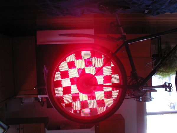
We have provided a blank canvas in the form of a scanning screen 15 LEDs by 7 LEDs and on this you can put anything you like.
Of course this is not a two-day job. You have to learn how to program and how to get the effects. But when you get something on the screen, you will be able to classify yourself as a PROGRAMMER.
Writing a program is a bit like writing a book. You have to think about a lot of things and actually invent many features. For instance, the design of each number and letter has to be determined. Then you have to decide how they are going to be stored and accessed. We have used one approach to displaying characters on the screen, but there are many ways to achieve the same result and you can start a-new or use our sub-routines.
The switches can be re-assigned at any stage and they can have more than one function.
It’s all up to you.
The first thing to do is go through the program and determine how each sub-routine operates. Then you can add your own ideas.
But remember this important point: Only add a very small step at a time.
Don’t expect a complex routine to work the first time.
Divide everything into small parts and make sure it works, before adding the next small step.
This is the only way to avoid frustration. You will learn a lot more about how to go about this process in this article and you can come out a successful programmer.
All the big signs are just an advancement on this project and once you have the concepts in place, you can tackle almost anything.
A point to note:
THE VOLTAGE
The voltage on the PIC chip is critical and the author had some random faults develop on the screen when the voltage dropped below 4.5v. As soon as any unusual fault develops, the first thing to do is check (replace) the batteries. The author also had a problem with the PIC chip when the supply was above 5.6v (in another project). So, be warned!

THE PC BOARD
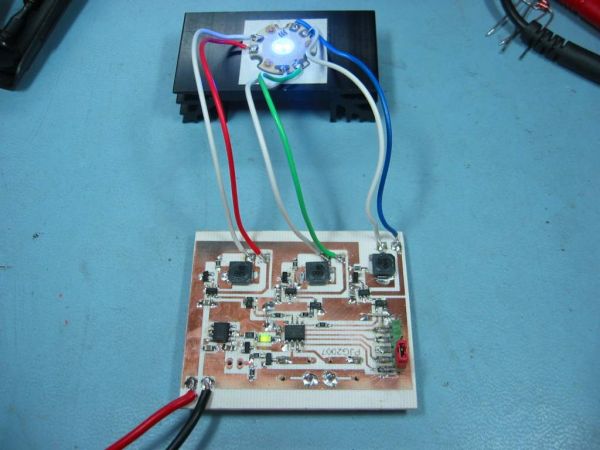
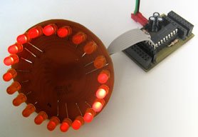
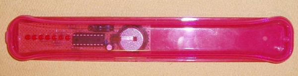
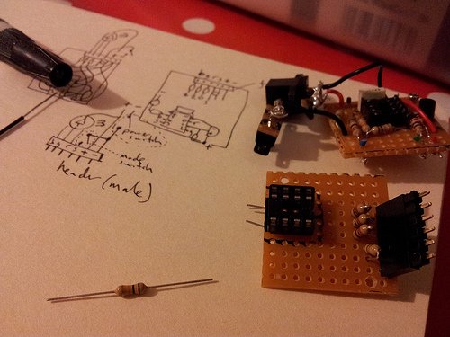
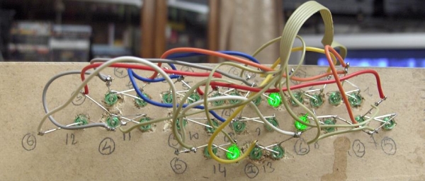
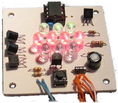
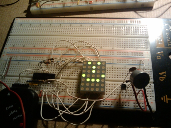
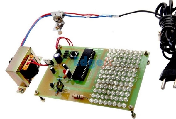
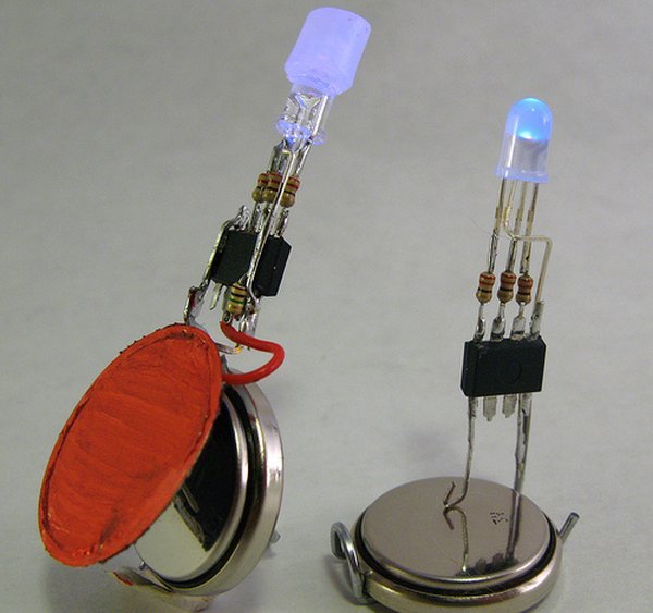
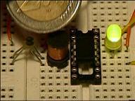
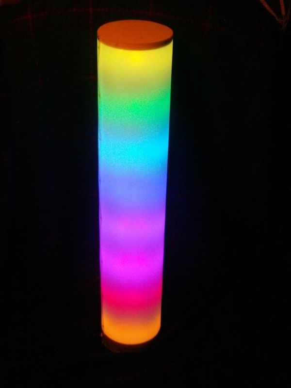
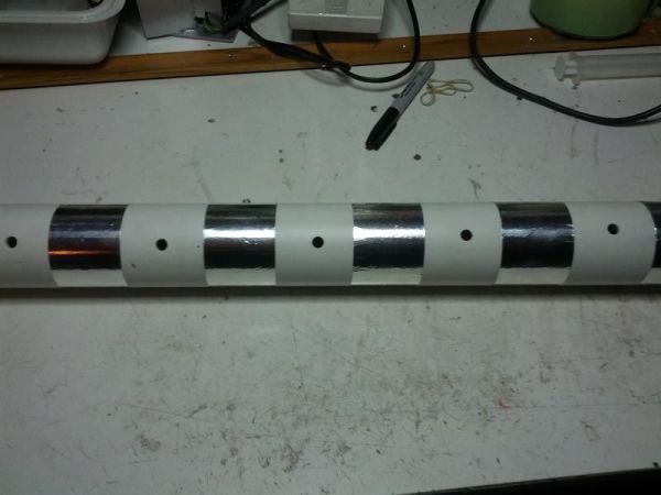
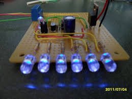
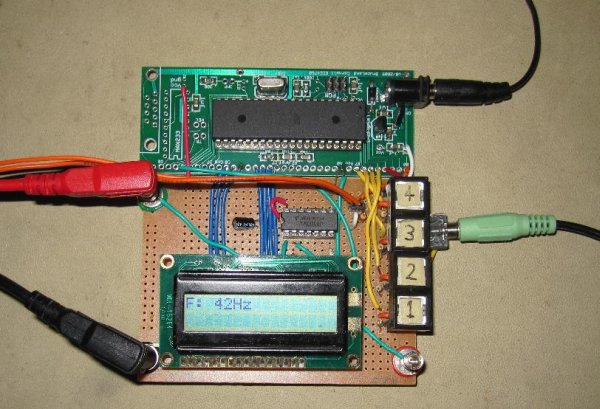
This project is provided as a “prototyping project” as no PC board has been produced. The photographs show the project built on a matrix board using surface-mount components and very fine wire.
The final design will require a double-sided board with plate-through holes, especially for the matrix of LEDs, but for the moment you can refer to the photographs and construct the circuit yourself.
Don’t be put off by the appearance of the circuit. It is really just a duplication of a very simple circuit driving a LED that can be built on a matrix board with 0.1″ spacing. Most of the surface-mount components can be positioned so the legs will reach a solder-land and you won’t need a special surface-mount board. But you will need good eyesight and a fine tipped soldering iron. Simply follow the layout and use the photographs as reference.
Let’s start:
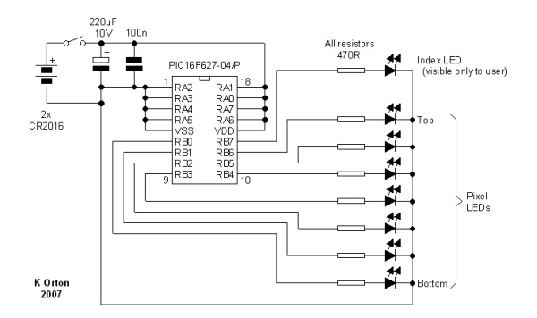
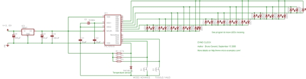
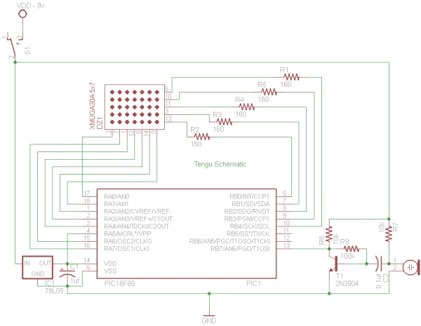
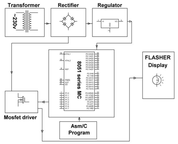
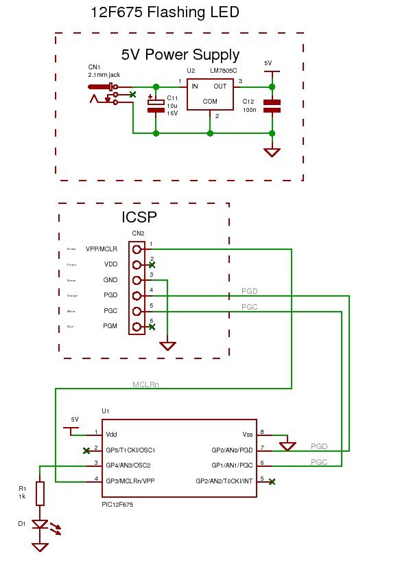
THE CIRCUIT
The circuit looks very complex but it consists of just two chips, 105 LEDs, a set of driver (buffer) transistors and 6 tactile switches. All the transistors and resistors seem to disappear when surface-mount components are used and the whole project can be constructed on matrix board or on a double-sided plate-through hole PC board.
Here is the circuit:
The 4017 is a “decade counter” and this means it has 10 outputs, starting with output pin 3, only one output is HIGH at a time. The 10th output is pin 11 and then the counter starts at pin 3.
The program starts by clocking the 4017 until pin 9 is HIGH. This pin is connected to the input of the PIC chip and the program now knows the state of the 4017.
This is called SYNCHRONISING. See more on this below.
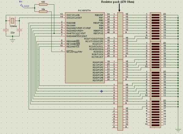
The ‘628 has two ports, Port A and Port B. Port A has 7 output lines (plus one input-only line) and Port B has 8 output lines. This creates our 15 lines for the screen. The screen is laid out as 15 LEDs “across” and 7 LEDs “down.” The data (or information) is fed in at the top of the screen from the PIC chip to the 15 LEDs and the LEDs are connected to the 0v rail via a transistor that is driven from the 4107 chip.
Each LED has an 82R resistor in series with the drive-line from the PIC chip and when you work out the voltage available and the value of the series resistance, you will find the current is about 30mA.
Since there are 7 rows of LEDs, each row is only turned on for 1/7th of the total time and this is why you need to drive the LEDs with a high current, as they are only getting a pulse for a very short period of time. Pulsing the LEDs like this produces a much brighter result than a constant current as your eye has a delay (or an extension) in seeing the illumination – called PERSISTENCE OF VISION and the end result is a very bright screen.
The top row is turned on for a short period of time as determined by a delay routine and then the drive-lines are turned off.
The information for the next line is then placed on the drive-line (port A and B) and the outputted to the screen. This also clocks the 4017 so the second row of LEDs is illuminated.
The program does not know which row of LEDs is being illuminated during the scanning process and that is why it is necessary to synchronize the two chips when the project is turned on, via a short sub-routine.
For the remainder of the running, the program assumes the two chips remain in synchronization. There is no reason why this will not be maintained, but it is not checked or verified at any stage. More on this under “SYNCHRONISING ” below.
This assumption is not allowed in an emergency environment but is perfectly suitable in our case.
For more detail: 15×7 Display using a PIC16F628 Microcontroller
Current Project / Post can also be found using:
- l e d pic
- led dinamico pic
- led projects
The post 15×7 Display using a PIC16F628 Microcontroller appeared first on PIC Microcontroller.