Quantcast
Channel: LED Projects - PIC Microcontroller
Viewing all 387 articles
Browse latest View live

Lissajous Figures on 8X8 Led Matrix

$
0
0

A point of light oscillating in 2 perpendicular axes draws a pattern named “Lissajous Figure” (1857) or “Bowditch Curve” (1815). Patterns range from simple to complex depending on the frequency ratio and phase of the 2 axes.A 1:1 ratio with 0 phase difference draws a straight line at 45° angle. In this project the frequency ratio of the 2 axes slowly sweeps back and forth between 1:1 and 2:1. These patterns are easily generated with an oscilloscope and 2 sine wave oscillators. In the mid 1800’s Joules Antoine Lissajous deflected a light beam with mirrors attached to tuning forks. He also created a SAND PENDULUM. This project displays Lissajous Figures on an 8X8 led matrix (or 64 discrete leds for a larger device) and is driven by a PIC16F627 microcontroller.

Step 1: Watch Video

The motion of the active led in pixels/second is around 20X the frame rate of this video. For that reason the patterns might appear to be “jumpy”. The real device has a much smoother visual performance.

Step 2: Schematic:

PIC16F627 is the heart of the project.

Step 3: Decoder

PORTB pins of the mcu drive the 8 common anodes (X-axis). PORTA (Y-axis / LED cathodes) has a maximum of 7 pins configurable as outs. To obtain the necessary 8 outs, 2 pins PORTA <1:0> drive a decoder made with 3 nand gates (74HC00) which provides 3 outs from 2 pins of the mcu.

Step 4: Generating the “sine” Waves:

The “sine” motion of the pixel is obtained by reading a succession of 22 byte patterns from a table in memory for the X-axis and the Y-axis respectively. The rate at which these patterns are read determine the period of the sweep.

Step 5: Table Read for PORT A

Table read for PORTA is slightly different to PORTB. Port A drives the cathodes and is Active-LOW. Pins 0 & 1 drive 3 common cathodes through 74HC00 nand gate decoder.

Step 6: Basic Flowchart

Download link to HEX & ASM code for PIC16F627

Step 7: Watch the Video

slow motion showing the movement of the active pixel

Source: Lissajous Figures on 8X8 Led Matrix

The post Lissajous Figures on 8X8 Led Matrix appeared first on PIC Microcontroller.


RGB LED Love Heart

$
0
0

This project creates a RGB LED lit love heart which is controlled by a PIC12F683 microcontroller.  I designed the project as a gift for my wife on our 15th wedding anniversary (since she puts up with my addiction to electronics I thought she deserved something in return!).

The love heart is made from a 200x150x6mm sheet of plexi-glass which is cut and sanded to create the optical effect and then mounted on the control board.  Even if you are not into microcontrollers the display can be easily adapted to show any shape (or shapes) you like; furthermore any high-intensity LEDs can be used allowing you to create a static light display using little more than some LEDs, resistors and a power source.

In this instructable I will walk you through the various steps and techniques used to make this unique display item.

Note: The high brightness LEDs, PWM colour mixing and the varying intensities confuse my video camera a lot and it seems that the camera is overly sensitive to blue.  Despite this I hope the video gives you some idea of how the display functions; the display outputs 35 unique colours fading between each.

Step 1: Items You Will Need

To build this project you will need some basic tools in order to work with the plexiglass.  In addition you will need a PCB (printed circuit board) which you can either make yourself, or use my supplied Eagle CAD files to order a PCB from one of the many board producers available on the Internet.

You will need:

1x 200x150x6mm sheet of plexi-glass
1x Aluminium tape
1x Double-sided sticky tape
1x P600 and/or P1200 fine grain sand-paper
1x sharp hobby knife
1x dot-punch
1x black fine-line marker pen
1x Printed Circuit Board
1x PIC12F683
1x DIP-8 IC Socket
3x 1K Ohm resistor
10x 56R resistor
5x 120R resistor
5x High-intensity RGB LEDs (common anode)
2x 100nF capacitors
1x 10uF capacitor
1x 7805 5V Regulator
1x 2.1mm DC Jack
3x BC337 NPN Transistors
1x 6 pin right-angle 2.54mm header (optional)

If you don’t want to build the more complex RGB LED controller you can use 5 high intensity red LEDs and resistors instead.

Step 2: The Controller Board

The controller board circuit diagram and PCB artwork are shown above.  The Eagle CAD files for these items are included with the project files so you can adapt and alter the design to your needs (as is the firmware for the PIC12F683 written in HiTech PIC C).

The board works by generating 3 software PWM signals from the PIC which control the overall brightness of the red, green and blue LEDs. Since the LEDs require 30mA per led colour the circuit must be capable of sinking 90mA per colour or 5x90mA = 450mA which is way over the rated maximum of the PIC. Therefore BC337 small signal transistors (which can handle 800mA each) are used to sink the current coming from the LEDs. The PIC controls the BC337 via 1K resistors which limit the current output from the PIC.

The sinking current to each LED colour is limited to 30mA by 3 transistors (one for each colour). Since the RGB LEDs I used have different ratings for the red channel (lower forward current) the red channel requires a different resistance value from the green and blue channels.

5 volts of power (at 1A max) is supplied by the 7805 voltage regulator. If you use a power supply of 9 Volts, you shouldn’t need a heatsink on the 7805 as it will run only at around 50-60C.

The PCB should be assembled starting with the smallest components (the resistors) and working up to the largest (the 2.1mm DC Jack).  As a final step you should insert the PIC12F683 into its DIP-8 socket.  If you want to program the PIC in-circuit (through the optional ICSP header) you will need to connect pins 2 and 3 from the header to Vcc and Vdd using some fine gauge wire in order for the ICSP programmer to function (I did not include this on the PCB as it would require 2 jumper wires which would degrade the clean look of the single-sided PCB design).  These wires can easily be added to the copper-side of the PCB.

The RGB LEDs I used are capable of being driven at 30mA and produce a lot of light.  You will need to check the datasheet for your LEDs and, if necessary, adjust the resistor values to make sure you do not supply too much current to your lights.  If in doubt use 150R resistors (which is usually a safe maximum for most LEDs).

Step 3: The PIC12F683 Firmware

The firmware is written in HiTech PICC and is included with the project files.  The firmware consists of an interrupt driven software PWM driver which controls the RGB LEDs at 100Hz and supports 32 brightness levels per colour.  RGB LEDs do not have a uniform output brightness across the 3 available colours; this means that you have to be careful to calculate the white balance (ensuring the each colour produces the same brightness when mixing colours).

To do this I used a standard LUX meter to measure the brightness of the individual LEDs and then entered the resulting information into a table in the firmware to ensure that the colour mixing was as even as possible.  The graph above shows the intensities of the colours within a LED across the 32 available brightness levels.  The white-balance table was created from the trend-line equations which are automatically generated by Microsoft Excel.  The second picture shows the set-up of the LUX meter used to create the graph.  All three colours we measured from a constant distance with LUX shown on the vertical axis and the brightness level (0-31) on the horizontal axis).

The white-balance varies from LED to LED so you may need to consult your LED’s data sheet, or simply experiment with the table’s values to make sure the resulting colours are correct for your RGB LEDs.

Step 4: Preparing the Plexi-glass

Cutting and drilling plexi-glass is a little tricky as the material is prone to melting and shattering.  As well as ensuring you use a relatively slow drill speed you should also ensure that you wear the correct protective equipment at all times.  In particular safety goggles are a must when working.

Drilling the 5 holes for the LEDs requires precision since the hole needs to be 5mm in diameter and the overall thickness of the material is 6mms giving a 0.5mm tolerance for mistakes (!)… Drilling with this much accuracy requires a 5 stage approach:

1) Firstly mark accurately the centre points of the LEDs from the PCB; although you can take these measurements from the design it is better to have made the PCB first and then (from the centre of the plexi-glass) mark off the centre positions of the 5 LEDs.  Once this is done measure and mark exactly 3mm from the edge of the plexiglass to create a cross for each hole (see the picture for details). 

2) Draw a line across the plexi-glass to show how deep you require the holes to be.  This will be 8-10mm depending on the design of the LEDs you are using.

3) Next use the dot-punch and (lightly!) punch a small indentation in the middle of every cross.  This will help guide the drill-bit into the correct spot and prevent it from slipping and giving you an off-centre hole.  You should be very careful to make the dot as central to your marking as possible.

4) Now take a drill-bit less then 2mm in diameter and (using the dot-punch marks) drill a hole down in to the plexi-glass which will be used to guide the main drill-bit in the next step.

5) As a final step use a 5mm drill-bit to drill out the holes to allow the LEDs to be mounted inside the plexi-glass.  Once the holes are drilled you should carefully remove any excess plastic in the holes.

Once completed the plexi-glass should fit snugly over the 5 LEDs on the controller board.

Note: Whatever you do, do not be tempted to peal off the plexi-glass’ protective plastic until you are completely finished handling the material… If you do it will get scratched and there is nothing you can do about it! 🙂

Step 5: Creating the Love Heart Design

To create the love heart design print out and cut out the template included in the project files.  Apply strips of double-sided tape across the plexiglass (make sure to use as much tape as possible so the template is held in position when you cut it later).

Apply the template to the plexi-glass ensuring that it is as smooth as possible.  Next take your hobby knife and cut around the outside of the template.  Make sure that you do not remove the knife from the surface whilst cutting.  Keep the knife pressed and rotate the plexi-glass as you go.  This will ensure that the heart’s outline is a single line without any ‘cross-hatching’.  Since all cuts and scratches in the plexi-glass will show once lit, this is important.

Once you have cut around the whole shape remove the paper.  Be careful not to scratch the surface as you go.  Once you have removed the paper use your knife to carefully lift the plastic protection from the plexi-glass within the heart shape (see the picture for an example).  You should now be left with an exposed heart-shaped area.

Using some P600 or P1200 sand paper carefully sand the exposed area from left to right and back again (don’t do this in random directions or the end-result will not look so good). You should ensure that you sand the whole area as evenly as possible (make sure to wipe away the excess dust to ensure that you have sanded the area evenly).  The combination of the paper template and the protective coating of the plexi-glass will ensure you only sand the correct area.

Once you have finished sanding remove the paper template and the protective plastic coating from the plexi-glass.  Now cut some strips of aluminium tape and cover the edges of the plexi-glass and the area in which the LEDs are to be inserted (look at the picture above for details).  The aluminium tape will bounce the light inside of the plexi-glass and make sure that the display is as bright as possible.

Using your hobby-knife make sure that you free up the holes for the LEDs as much as possible to ensure that the LEDs fit without problems.

Finally insert the LEDs on the control board into the plexi-glass.  The LEDs should fit snugly and should not require glue to hold the display in place.  If required use a hot-glue gun to ensure that nothing can move.

You are now ready for action!

Step 6: Project Files

Attached you will find the project files including the heart template (in PDF format) the HiTech C firmware and the Eagle CAD schematic and PCB files.

I hope you have fun building your own RGB LED plexiglass design and, if you decided to build a love heart, that your wife/girlfriend appreciates it as much as mine did 🙂  !

If I had access to a laser engraver and cutter it would be possible to create far more detailed display designs by using the laser to etch the surface to transfer complex artwork to the plastic. Furthermore it is possible to paint the plexiglass and use a laser engraver to remove the paint and surface to create a far more contrasting design.  I hope the Epilog Challenge Contest can help me out with this and future projects! 😉

Attachments

Source: RGB LED Love Heart

The post RGB LED Love Heart appeared first on PIC Microcontroller.

Led Blinking by Basic Language Using PIC16f877A

$
0
0

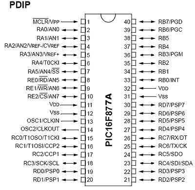
PIC16F877A Pin out & Descriptions

There are 5 ports that provide parallel I/O Interfaces to outside world PORTA, PORTB, PORTC, PORTD, PORTE

Each port provides 8 bidirectional digital I/O lines which are connected to PIC16F877A pins provided that alternate functions are not selected on that Port.

Eventhough Bidirectional at nay time the I/O line can either be INPUT or OUTPUT.

By clearing some bit of the TRIS register (bit=0), the corresponding port pin is configured as output. Similarly, by setting some bit of the TRIS register (bit=1), the corresponding port pin is configured as input. This rule is easy to remember 0 = Output, 1 = Input.

Step 1: Connection of LEDs With a Port

Let us assume that 8 LEDs are connected to 8-pins of PORTD of an PIC16F877A chip.

We want to glow eight LEDs alternately. [If ‘1’ is sent, the corresponding LED glows]

And they will toggle at every 1 sec and it will be repeated continuously.

Write a C code or Basic code for the above mentioned output operations

Light Emitting Diode (LED) is a special diode that emits light when electric voltage is applied to it. It is a common electronic equipment used in many devices for indication purpose.

Step 2: Project Video

Attachments

Step 3: Summary Action During Output

Step1: If we want to read (in) data through a pin of a port, the corresponding bit of TRISx Register has to be set to ‘0’.

Step 2: Whatever data is in that pin of the port the data will appear in the corresponding bit of TRISx register.

Step 3: Each pin has a provision of connecting a pull up resistor internally. If we want to connect that resistor, we have to write ‘1’ to the corresponding bit of PORTx register.

Note: At START UP or UPON RESET, TRISx register contains 0x00. That is the port remains at Input state. But if it is used as OUTPUT at one stage of program, afterwards, we can not read data from a pin if we do not complete step 1.

Step 4: PIC SIMULATOR IDE

PIC Simulator IDE is powerful application that supplies Microchip microcontroller users with user-friendly graphical development environment for Windows with integrated simulator (emulator), pic basic compiler, assembler, disassembler and debugger. PIC Simulator IDE supports the extensive number of microcontrollers (MCUs) from the Microchip 8-bit PIC Mid-Range architecture product line (selected PIC16F, PIC12F, PIC10F models).

Step 5: Code

Define CONF_WORD = 0x3f72

Define CLOCK_FREQUENCY = 12 ‘clock frequency

AllDigital ‘all ports goes to digital

TRISD = 0x00 ‘PORTD output

PORTD = %00000001 ‘RD0 is on and other pin off or zero

goleft: ‘for left shift loop

WaitUs 500 ‘delay 500us

PORTD = ShiftLeft(PORTD, 1) ‘portd shiftleft from rd0

If PORTD.7 Then Goto goright ‘when RD7=1 then goto loop right shift

Goto goleft ‘repet loop

goright: ‘right shift loop

WaitUs 500 PORTD = ShiftRight(PORTD, 1) ‘shift right

If PORTD.0 Then Goto goleft ‘when RD0=1 then goto left shift loop

Goto goright

Source: Led Blinking by Basic Language Using PIC16f877A

The post Led Blinking by Basic Language Using PIC16f877A appeared first on PIC Microcontroller.

Serial communication with Matlab

$
0
0

Overview

Matlab has a “serial” function that allows it to communicate through a serial port. This project is to establish serial port connection with the PIC microcontroller and demonstrate bidirectional communication between the PIC and a Matlab program. For demonstration purposes, the PIC will send digital potentiometer readings to Matlab as well as receive keystrokes from the Matlab user to light up LEDs on its circuit board.

A USB to RS232 adapter and level shifter chip were used to connect the computer to the PIC. In this lab, we used a cheap cable found at http://cgi.ebay.com/ws/eBayISAPI.dll?ViewItem&item=220199148938&ih=012&category=41995&ssPageName=WDVW&rd=1


**Important! DO NOT connect the serial Rx/Tx lines DIRECTLY to the PIC!!!**

A level shifter chip is necessary to convert the high and low logic voltages from the desktop computer (+12V/-5V) to (+5V,0V) for the PIC. A standard RS232 connection is called a DB9 connector and follows the pin diagram shown here: http://www.aggsoft.com/rs232-pinout-cable/serial-cable-connections.htm This cable requires 1 driver installation as included on the mini-cd. To install this driver, you must first plug in the USB cable, and run the installation program located on the CD corresponding to the model on the USB Cable (<CDROM>:\HL-232-340\HL-340.exe). This driver is also available online at this link: http://129.105.69.13/pic/usb_drivers/HL-340_USB_serial_drivers_WinXP/ . To configure the Matlab script to connect to the proper serial port, use the device manager (Right click My Computer->manage) and expand the section “Ports (COM & LPT)”. Make a note of the COM port number corresponding to “USB-SERIAL CH340” as listed in this section. In our program, our serial port was COM4. A picture is shown below of how to get this information in the device manager.

A female DB9 connector was wired to our level shifter to convert the voltages, with the level shifter connected to our PIC. The female DB9 connector is used so no wires need to be directly soldered to the serial cable. Refer to the Circuit section for details on this connection.

The PIC was programmed with our C code as shown below. Our program was designed to read a potentiometer through the PIC’s ADC (Analog to Digital Converter) port and transmit the digitized readings over the serial cable to the PC (upon request). In Matlab, if a users sends data to the PIC by entering a character, the PIC responds with the current potentiometer reading and the last received byte from the PC. The PIC is also programmed to display the character received from the PC on its LED array (D register) as a 8-bit ASCII number. The programs can easily be modified to create any custom protocol, but are designed to show simple 2-way communication between Matlab and the PIC.

Circuit

COM Port Lookup – Device Manager

The wiring diagram for serial communication is shown below. There are three basic components in this setup. The potentiometer serves as an analog input to the PIC, which is converted to a digital signal through the PIC’s analog to digital converter pin. The MAX232N level converter provides bidirectional voltage shifting for digital communication between the PIC and PC (read more about this chip and level conversion on the RS232 wiki here). Finally, the female DB-9 connector allows the circuit to connect to the PC’s serial port.

Circuit Diagram for Serial Communication between PIC and PC

The connections to the female DB-9 adapter are shown below. These wires are soldered to the cup-side of the adapter, not directly to the serial cable. Our DB-9 adapter is pictured below and follows the given connections:

PIN5:DB-9 (green wire)  ->  Common Ground
PIN3:DB-9 (yellow wire) ->  Receive (RX)   ->  PIN14:MAX232
PIN2:DB-9 (white wire)  ->  Transmit (TX)  ->  PIN13:MAX232
Closeup of DB-9 Connector

Our final circuit is pictured below.

Image of wiring for serial communication between PIC 18F4520 and PC

PIC Code

/*
   SerialComm.c Scott McLeod, Sandeep Prabhu, Brett Pihl 2/4/2008
   This program is designed to communicate to a computer using RS232 (Serial) Communication.
   
   The main loop of this program waits for a data transmission over the Serial port, and
   responds with a current reading of an analog input (potentiometer) and the last received data.
  
   Note the analog input is only for testing purposes, and is not necessary for serial communication.
   Lines unnecessary for RS232 communication are commented with enclosing asterisks ('*..*').
 */
 
#include <18f4520.h>

#fuses HS,NOLVP,NOWDT,NOPROTECT
#DEVICE ADC=8                          // *set ADC to 8 bit accuracy*
#use delay(clock=20000000)             // 20 MHz clock
#use rs232(baud=19200, UART1)          // Set up PIC UART on RC6 (tx) and RC7 (rx)  
 
int8 data_tx, data_rx = 0;             // Set up data_tx (transmit value), data_rx (recieve value)
 
void main()
{
   setup_adc_ports(AN0);               // *Enable AN0 as analog potentiometer input*
   setup_adc(ADC_CLOCK_INTERNAL);      // *the range selected has to start with AN0*
   set_adc_channel(0);                 // *Enable AN0 as analog input*
   delay_us(10);                       // *Pause 10us to set up ADC*
   
   while (TRUE)
   {
      data_tx = read_adc();            // *Read POT on analog port (0-255)*
      output_d(data_rx);               // Output last recieved value from computer
      delay_ms(10);
      
      if (kbhit())                     // If PIC senses data pushed to serial buffer
      {
         data_rx = fgetc();            // Read in recieved value from buffer
         printf("Pot: %u Char: %u\n", data_tx, data_rx);  // Once data sent and read, PIC sends data back
 
         //delay_ms(10);               // As tested briefly, this delay is unnecessary for our (relatively) slow data rate
                                       // If you are receiving data errors, you may want to introduce a slight delay
 
 
      }
   }
}

Tips on Designing a Protocol

A good way to start or debug your program is to use the PIC-C Serial Port Monitor (Tools Tab->Serial Port Monitor). This will allow you to send and receive raw data over the serial port, which is much easier for understanding why a protocol isn’t behaving correctly. You can also use HyperTerminal on windows XP (Start->Programs->Accessories->Communications->HyperTerminal), although in our testing this appeared to be less stable than the PIC-C Compiler’s monitor. Note for both programs, you will have to configure which serial port to monitor using the same method described in the Overview.


Be sure to close all other programs accessing the serial ports (PIC-C/Hypterm etc.) if you are having difficulty opening the port in MATLAB.

Matlab Code

**** THIS MATLAB CODE SHOULD BE UPDATED TO USE “fread(s,1)” instead of “fscanf(s)”. fread(s,1) reads 1 bitwise value at a time (opposed to an ascii value). Without this change, matlab can only read 8 bit ASCII characters and will reject a subset of the values between 0 and 255. *****

If your program doesn’t close and delete the serial port object correctly, you can use the command shown below to delete all of the serial port objects.

delete(instrfind)
%  SerialComm.m  Scott McLeod, Sandeep Prabhu, Brett Pihl 2/4/2008
%  This program is designed to communicate to a PIC 18F4520 via RS232 (Serial) Communication.
%  
%  The main loop of this program waits for a character input from the user,
%  upon which it transmits the ascii value and waits for data to be written.

s = serial('COM4','BAUD',19200);            % Create serial object (PORT Dependent)
fopen(s)                                    % Open the serial port for r/w

myChar = 'a';                               
prompt = 'Enter a character (q to exit): '; 

while (myChar ~= 'q')                       % While user hasn't typed 'q'
    fprintf(s, '%s', myChar(1))             % Write first char of user input to serial port
    fprintf(fscanf(s))                      % Read Data back from PIC
    myChar = input(prompt, 's');            % Get user input
end

fclose(s);                                  % Close the serial port
delete(s);                                  % Delete the serial object

Source: Serial communication with Matlab

The post Serial communication with Matlab appeared first on PIC Microcontroller.

LED Amusement Park

$
0
0

Overview

Our project consists of a 2m DotStar LED strip with 120 individually addressable LEDs and seven accelerometers with the Big Board to depict three different rides that are typically found in an amusement park: the roller coaster, the drop tower, and the bouncer. We implement 1D kinematic equations iteratively to approximate the real-world physics motion on the LED strip. We use multithreading to program the PIC32 processor on the Big Board and use SPI and I2C communication protocols to communicate with the LED strip and accelerometers, respectively. We also created a user interface in Python to easily change various settings of the rides and debugged the system using an oscilloscope and a TFT display.

High Level Design

Rationale and Sources of Project Idea

Due to COVID-19, it is not safe for anyone to go anywhere that is crowded. One of the most densely crowded places is an amusement park. We wanted to bring in some of the excitement that we feel at the amusement parks into our lab. Instead of mechanically building a ride, as electrical engineers, we decided to take a more electrical approach to this: LEDs. We thought this would be a creative yet still exciting way to simulate a small amusement park.

All the amusement park rides are thoroughly calculated and calibrated to be safe and bring excitement to people. Since our rides are on a LED strip and most of the excitement comes from viewing the ride instead of riding it, we were able to simplify the physics that were involved with the rides and put more emphasis on making it look more interesting.

Logical Structure and Background Math

The LED strip represents an amusement park ride, and the light that travels through the LED strip represents the riders. The accelerometers are attached to the back side of the LED strip at a regular interval. The accelerometers return the angular velocities and linear accelerations in the 3-dimensional space. We first tried to calculate for the absolute position and shape of the LED strip in the 3-dimensional space from the accelerometer readings, but we soon found that this is very difficult to do. One way to do this is by iteratively calculating the updated position of each accelerometer from the initial position of the LED strip through the readings of the accelerometers. This can be done by first calibrating the LED strip at a known initial position, e.g. flat on the table, and slowly moving to the desired shape. Meanwhile, the angular velocities are converted to linear velocities through approximations and the 3D accelerations are used in the 3D kinematics equation to iteratively calculate for the final position and shape of the LED strip. However, we concluded that this approach is not preferable because these calculations involve many approximations, e.g. the radius when converting from the angular velocity to the linear velocity, and the accelerometer readings are very noisy. The approach we took was to use only the y-acceleration reading from the accelerometer that is closest to the current position of the riders, i.e. the LEDs that are on. The LED strip reduces the dimensionality that we need to take into account to 2D because the riders can only move in 1D motion along the LED strip and gravity adds another dimension to the system. There is also friction, but this is along the LED strip, so it doesn’t affect the dimensionality of the system. Essentially, we only need to calculate the next LED position to turn on, which could be done with the 1D kinematics equation given the initial velocity and position along with the y-acceleration. The value of y-acceleration returned from the accelerometer depends on the slope of the LED strip. (Note that when the IMU is sitting flat on a table, only its z-acceleration should be non-zero, and more specifically should be the force of gravity). We iteratively update the y-acceleration from the closest accelerometer, current velocity of the cart using the velocity of the previous time frame along with the closest y-acceleration reading, and position from the position and velocity from the previous time frame, all using the basic kinematic equations below. Doing this meant that we did not need to calculate the absolute shape and position of the LED strip.

We believe this method allows us to achieve better performance in terms of how smoothly the riders move through the LED strip when we change the position and shape of the LED strip in real-time, because updating the entire position and shape of the ride is more expensive than updating for the new position of the riders from the previous values.

Hardware/Software Tradeoff

One step we took to get less noise in the readings of the IMUs is pass them through a low pass filter. Instead of using a physical RC filter which would add to the space and budget requirements of the project and still be noisy due to imperfect components, we neglected the four least significant bits in the readings in software. This was a simple, single line of code, but it allowed us to receive much more consistent readings in the IMUs, and hence update the LED cart’s position in a more pleasing manner.

Software Design

There are three main types of threads: a thread for reading the IMU, a thread for calculating and updating the LEDs to light up in the next time frame, and threads for the Python user interface.

The IMU makes use of the IMU library inspired from the one we cited in the References section of this report. Using this IMU library, we read the values from each of the seven accelerometers on the LED strip. By assigning to global variables, we can use these values to update the next LED positions to light up in the LED thread. This way, we can dynamically change the position and shape of the LED strip and the movement of the riders will change accordingly in real-time. Also, it is important that we use the bit-shifted IMU readings rather than the raw values from the accelerometers, since the accelerometers are very noisy. Using raw values can lead to abrupt jumps in the LED positions, which leads to unnatural-looking behaviors of the riders through the LED strip. We right-shifted then left-shifted by 4 bits, and this seems to sufficiently reduce the noise, leading to natural-looking behavior of the ride. We yield this thread for 50 ms, i.e. we read from the accelerometers around 20 times a second.

The LED thread is where most of the calculation happens. In this thread, we first check the current position of the traveling light (the position of the LED that is turned on to denote where the riders are in the current time frame) on the LED strip, and use the reading of the accelerometer that is closest on the LED strip as the acceleration value. Note that the imu_reading array has length equal to the number of the accelerometers (currently 7) and has the values updated by the IMU thread explained above. Then, we check the current mode, which indicates whether it is in the roller coaster, the drop tower, or the bouncer mode. For each of the modes, a different kinematic equation is used to update the position of the traveling light in the next time frame. For the roller coaster mode, we used the equation indicated in the High Level Design section. For the drop tower mode, we use the same equation but we added an upward movement at the beginning of the ride, which travels at a constant speed, to mimic the behavior of the ride more closely. We also wait at the top of the ride for a random amount of time to increase suspense. For the bouncer mode, we use the two different equations: the same equation as the roller coaster mode when it is moving downward and the equation with the negative speed once it reaches the end of the strip and travels back up the LED strip. Because each mode behaves slightly differently even with the same equation, we controlled this through the amount of time to yield the thread until the next update to the traveling light position. For example, the drop tower drops at the same speed as the speed at which a real object is dropped, whereas we controlled the speed of the roller coaster so that we can visually examine that its behavior is clearly affected by the physics and the shape of the roller coaster. We used the Dotstar example code from the course website to send the updated values for each pixel on the LED strip (cited in the References section of this report).

The Python user interface was created so that the amusement park could be more interactive. Users can choose the ride that they want to go on, the initial velocity of the ride, numbers to simulate friction, and even what color and how long the ride train should be. It also includes a reset button to restart the ride with the parameters that are set. An image of the interface is shown below. We use radio buttons to choose the ride, a normal button for the reset, and sliders for the remaining settings, so we include threads to support those functions in our code. These threads yield until an event happens on the interface. We used the sample code provided on the course website to help us with that (cited in the References section of this report).

The main() function handles all of the initialization, including initializing and scheduling the threads, opening an I2C channel for the IMUs, setting up each IMU (by assigning each of them a separate GPIO address pin, taking them out of sleep, and setting the accelerometer range to +-2g), opening a SPI channel for the LED strip, and turning off all of the LEDs on the strip.

Hardware Design

The main components in our project are the PIC32MX250F128B microcontroller, an Adafruit DotStar LED strip, seven MPU6050 IMUs, and a USB to TTL serial cable for our Python interface. A full hardware schematic can be found in Appendix C.

DotStar LED strip

The LED strip we use communicates with the PIC32 using 2-wire SPI. Because the LED strip is a 5V device while the PIC32 is a 3.3V device, we use the 74AHCT125 level shifter to translate the clock line and the data line from 3.3V to 5V in order for the microcontroller to be able to communicate with the LED strip.

IMUs

The IMUs we use are MPU 6050 chips on individual breakout boards that each communicate with the PIC32 using I2C. Each IMU has two address options, 0b1101000 and 0b1101001. One pin on the breakout board is used to toggle the last bit of its address. We are able to connect more than two IMUs by dynamically changing each sensor’s addresses when we wanted to read to or write from it. We use the 0b1101000 address to communicate with the sensor. This means that when we want to talk to a specific IMU, we clear that chip’s address pin and set all the others’ address pins. Each sensor’s address pin needed to be individually mapped to a GPIO pin on the PIC32 in order to be able to be independently manipulated. This was a pin-intensive undertaking, and we had to carefully avoid pins that were already being used by other parts of the project, such as those for the UART connection for the Python interface and the SPI connection to the LED strip.

Before we set up all of the sensors in our system, we tested them individually to make sure that they all worked. From our testing, we realized that the readings were quite noisy even when the sensor was sitting still on a surface. To reduce the jitter, we low-pass filtered the readings in software by shifting the four least significant bits of the readings out, and shifting zeros in. This reduced noise and allowed for a more smooth ride.

USB to TTL

To make our project interactive, we set up a USB to UART connection so that the user could manipulate variables in the user interface (a Python program) and the changes would be reflected in the running C program immediately, ensuring that the baud rate matches between the C program and the Python program.

Squashed Bugs, Failed Attempts, and Other Notes

One problem we came across with the LED strip was its direction. Because each LED is essentially daisy-chained in the strip, one side of the LED strip counts as the input and one as the output. Initially we were not receiving any response from the LED strip because the I2C signals from the microcontroller were not being sent to the correct side of the LED strip. After looking closer, we realized it was important to pay attention to orientation.

One important issue we had with our design was the PIC32 only outputting a peak to peak voltage of 3.3 volts. The LED strip required a voltage of 5 volts for both the data and clock line. After several attempts of connecting the LED strip to the PIC32 and not seeing any response, we realized that we needed to use a level shifter. The pinout of the level shifter we used (74AHCT125) is shown below. The “A” pins are the 3.3 volt pk-pk inputs from the microcontroller, and the “Y” pins are the 5 Volt outputs to the LED strip. The “OE” pins had to be grounded in order for the outputs to be enabled. Note that we only used two out of the four channels available on the chip: one for clock, and one for data.

The amount of wires we used to connect each of the sensors to the PIC and the LED strip oftentimes became overwhelming to keep track of. We tried our best to color code the wires so that we could easily tell which wire goes to which pin. We also made sure to add tape to wire openings, so they would not short. For example, the ground and power pins for the power of the LED strip were left floating since they were internally connected to the Dotstar MCU inside of the LED strip. We taped the ends of these wires so the power and ground would not accidentally touch each other and short. If there were any other wires which were stripped and we noticed they may easily touch, we taped these wires so that there was no possibility of shorting and destroying the IMUs or the PIC.

As a side note, we tried to use less wires by creating the wire harness shown below, but it ended up being even more problematic when we were trying to debug our project because of the poor connections.

One frustrating bug we encountered was not properly taking the sensors out of sleep mode. This happened as an artifact from when we had done IMU testing one by one. When we were adding sensors by mapping a new GPIO pin to each, we neglected to also initialize each of the sensors we were adding. The way the code was initially formatted caused us to only be initializing the last sensor we added, which resulted in a confusing false positive where they all seemed to be working when we added each sensor one by one (since they would all retain their state of having been taken out of sleep mode) but all of a sudden wouldn’t work when we ran the same exact code again the next day and/or power cycled the big board. This problem was only exacerbated by the fact that we didn’t know whether it was a hardware issue with wiring, or a software issue.

Another interesting thing to note is that the I2C protocol was intended to only be used for intra-board communication, but could be pushed to longer distances with a lower clock frequency. With a peripheral clock frequency of 40 MHz, we set our I2C clock frequency to be 100 kHz by setting the I2CxBRG register value to be 0xC2.

Results

Our project successfully was able to demonstrate three different amusement park rides with our LED strip. Our design focussed on making the entire “roller coaster” and other rides look as natural as possible. In order to achieve this, we made sure to choose yield times that were small enough so that the LED carts’ positions could update as soon as possible, and the sensor readings would be read as soon as possible. We tried to eliminate any additional threads that were not needed during our final design. For example, one of the print threads, which was printing the sensor readings of each IMU to the python interface, took a long time to execute. Hence, we noticed pasues in our LED roller coaster, probably due to it waiting for everything to print out before continuing onto the other threads. After removing this, we were able to see a much smoother execution.

In order to demonstrate the “realistic” movements of our roller coaster, we tried several different configurations during the demo. We had the LED strip in the shape of a parabola, so that it would settle down close to the minimum of the parabola. We tried a loop, so that we could see that the LED cart would slow down at the very top of the loop, and then speed up on the way down.

Another important result we wanted to highlight was our free fall “drop tower” ride. This was a simple drop tower, composed of the LEDs climbing to the top of the strip, and then waiting for a random amount of time, and then falling down at nearly exactly the acceleration of gravity. We were able to demonstrate the accuracy of this by dropping a pen right as the LED cart fell down, and they dropped at nearly identical speeds.

One result of our design that slightly brings down the “natural” quality of the roller coaster is the lack of additional sensors. Since our algorithm works based on the acceleration detected by the closest IMU to the LED cart, the behavior of the LEDs in the middle of two IMUs is erratic. Hence, if we were able to use more sensors, we would have less of this behavior, since there would be less space between the sensors.

Demo

Conclusions

We believe our design accurately replicates the movement of rides at an amusement park, and we were able to demonstrate three different rides. Our final product exceeds our expectations, and we were able to create a project that could dynamically respond to our movements and orientation of the LED strip, which we had envisioned from the beginning.

As mentioned earlier, one thing we would like to improve on is adding more sensors to our design. More sensors would give our LED cart more accuracy whenever it updates its position, and it wouldn’t awkwardly stop in the middle of two sensors if one is at a horizontal position. The addition of more sensors would be a simple task, but we decided to remain within a more reasonable budget for the purpose of this project.

In order to make this project also much more aesthetically pleasing, we could include additional colors while the LED cart is moving throughout the LED strip. For example, if the cart is moving faster, it can be changing colors more rapidly, and while it is moving slower it can gradually change colors to offer a visually pleasing experience for the user.

The use of sensors to get data was a great way to get more experience in using I2C devices. However, after thinking about it more and getting feedback from the professors, another way we could also get a similar effect is if we were able to use computer vision on the LED strip, and based on how it was oriented, change the velocities of the LED cart. This would require a much more software-focused approach, but could be an interesting improvement for the future.

Our design used several important concepts that we learned in class. The communication with the LED strip was through SPI, and communication with each of the IMUs were through I2C. We also interfaced with an external Python GUI through UART, which could control the color, initial velocity, and length of the cart, and the mode of the ride. We made sure to properly configure each of the threads, and were cautious to make sure that the threads did not interfere with each other when yielding between them.

We believe we meet all ethical, safety, and legal standards.

Appendix C: Hardware Schematic

Source: LED Amusement Park

The post LED Amusement Park appeared first on PIC Microcontroller.

48 Channel Mono / 16 Channel RGB LED Controller using PIC18F2550 microcontroller

$
0
0

48 Channel Mono / 16 Channel RGB LED Controller

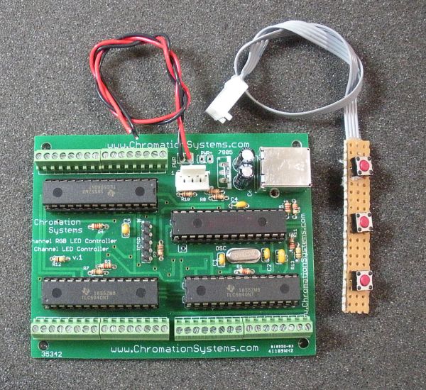
The 48 Channel Mono/16  Channel RGB LED Controller by Chromation Systems can be used to independantly control 48 groups/channels (up to 120ma per group) of mono-color LEDs or 16 groups/channels of common anode RGB LEDs. It utilizes 3x TLC5940 LED drivers controlled with a PIC 18F2550 microcontroller. The PIC runs at 48mhz, has USB connectivity and controls the drivers through a modified SPI interface. The default firmware uses 8-bit PWM(256 brightness levels) and has a 1.5khz PWM frequency. All LED anodes are connected in parallel and the cathodes are connected to the controller as the outputs sink current. There are 3 connection options for the LEDs, direct soldering, screw down terminal blocks, and headers/housings.


16 Channel RGB LED Controller
The primary firmware for this device is ColorMotion compatible, which works with the Chromation Systems ColorMotion Software. ColorMotion is used for creating and uploading RGB patterns to the device.  The source code for ColorMotion Compatible Firmware is not available, but a few variations of sample code, including basic RGB LED control and USB communication is available in the project files below.

For more detail: 48 Channel Mono / 16 Channel RGB LED Controller using PIC18F2550 microcontroller

The post 48 Channel Mono / 16 Channel RGB LED Controller using PIC18F2550 microcontroller appeared first on PIC Microcontroller.

Mood vase using PIC12F683 microcontroller

$
0
0

Intro:

Mood vase

I’m a fan of LEDs, lots of LEDs.  So here’s a slightly less crass way of using LEDs for decorative purposes.

While this is by no means a neat and polished solution, and probably not the first of its kind, however the pulse effect is as far as I have seen unique, and exactly what I wanted.  I hope that this will inspire others to create similar.

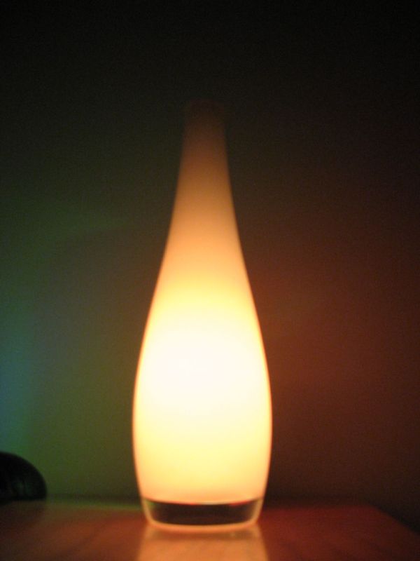
The set-up It consists of a plain, unmodified vase, and a small battery-powered unit that sits behind a vase and shines three LEDs to give some nice ambient color.

The circuit is powered by a microcontroller, in my case, a PIC12F683, I’ve included source code for the PIC12F683, but presumably it can easily be ported to Atmel or other microcontrollers.

I am writing this instructable for those with experience with circuits and microcontrollers, I am happy to answer any questions anybody has.

Mood vase

Step 1:

The Circuit: overview

The circuit can be split into 5 parts:
1. The brains – this will control the LEDs and produce the colours and pulses of light
2. The power – I use lithium-ion cells, but the circuit works perfectly well using 3AA or AAA batteries typically this will run the circuit from a week up to a month depending on battery.
3. Light detection – this is so that the circuit turns on only when dark
4. Voltage reference – this is needed for low-battery detection, for lithium-ion cells, this is important since over-discharging damages the cells.  For AA or AAA batteries, this is less important.
5. LEDs!

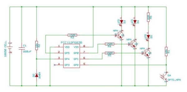
The circuit diagram is below, there’s also a PDF with the same diagram since the picture is a little small and blurry.

You will need:
– PIC12F683 or other microcontroller
– either 1x 18650 or 3x AA
– 220uF electrolytic capacitor (or any value larger than 1uF)
– 10k resistor + zener diode (or 1N4001, see later)
– 3x 150R resistor, 3x NPN transistors
– 3x high-intensity LEDs, 3x 20R resistor (see later)
– 40k resistor, phototransistor

Schematic Mood vasa

Step 2:

The Circuit: Part 1

1. The circuit is powered by a PIC12F683, which I favour for its small footprint (8-pin package).  For this application, we don’t need much more processing power than this very basic microcontroller.

One major advantage of this particular family of microcontollers is the fact that they can run off any voltage supply from 2V up to 5.5V, without the need for a regulator.

2. Therefore the power supply needs to be between 2V and 5.5V, you can either use 3 AA or AAA cells (3v – 4.5v), or a single lithium ion cell (3v – 4.2v).  I used a 18650 lithium ion cell since I had a whole bunch lying around (you can find 8 cells in most laptop batteries).

Step 3:

The Circuit: Part 2, optional parts

Optional parts:
3. Light detection:  Adding light detection allows the LEDs to only turn on when dark.  This is achieved simply using a phototransistor and resistor.  (Or a photodiode + transistor combo)

When light falls on the phototransistor, a current flows, pulling the voltage after the resistor down.  The resistor needs to be sized so that there’s a decent voltage swing between light and dark that the microcontroller can detect.  I used a photodiode + transistor, with a 40k resistor.

4. Voltage reference:  This allows for low-battery detection.  For Alkaline AA or AAA cells, this is not important.  For NiMH, NiCad and Li-ion cells, over-discharging them may cause damage.  The PIC compares the voltage reference with battery voltage.  And stops turning on the LED when the voltage is too low.

You can use either a zener diode, or failing that, a general purpose diode is sufficient.  I used a 10k resistor and a 1N4001 diode.


For more detail: Mood vase using PIC12F683 microcontroller

The post Mood vase using PIC12F683 microcontroller appeared first on PIC Microcontroller.

3x3x3 LED Cube using PIC16F690 microcontroller

$
0
0

3x3x3 LED Cube

Here is my 3x3x3 LED Cube project. It runs using a PIC16F690. Along with the brief explanation of how to make it, I have also included the .asm file for the PIC and a piece of software written in VB.NET that you can create your own LED patterns. These can be exported as .asm files and put into the main .asm code.

3x3x3 LED Cube

Building

Each layer of 9 LEDS are connected with all of the cathodes together. The cube is multiplexed, meaning that only one layer is on at any one time. It happens so quickly that the whole cube looks like it is illuminated. RB5, RB6 and RB7 controll which layer is being illuminated.

From the picture you can see the connections to the top layer. I have only connected RC2 to show you how the connection should be made, the rest of the LEDs are connected the same way.

Schematic 3x3x3 LED Cube
The easiest way to connect the LEDs together is to drill 9 holes into a piece of wood (picture 2), then place the LEDs into the holes, bend the legs and solder the cathodes together. After 3 of these are created, simple stack them and solder the anodes together. You should end up with 9 anodes and 3 common cathodes to connect to you circuit.

For more detail: 3x3x3 LED Cube using PIC16F690 microcontroller

The post 3x3x3 LED Cube using PIC16F690 microcontroller appeared first on PIC Microcontroller.


8×8 LED matrix using PIC16F690 microcontroller

$
0
0

8×8 LED matrix

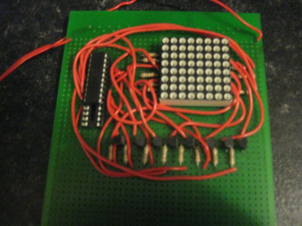
This instructable will show you how to make a 8×8 LED matrix in witch you can control evry single LED and create your own patterns as long as they only need 64 pixels to show them in one color.Update 25.09.10
LED matrix
I’ve added a pattern generator to create patterns but not all of it’s features are complete

Materials

Materials you need:
-8x8LED matris (can make one but i bought mine)
-16x120Ohm resistors
-8xNPN transistors (I used C547B)
-1xPIC16f690
-prototype board (or you can make pcb for this)
-wire
-5V power supply (you can use a voltige regulator but I just power mine from a usb port)Tools:
-PIC programmers (all the pic programmers from microchip exept for pickit1 will work)
-Software- MPLAB (free software from microchip)
-Soldering iron
-A vacum pump for removing solder is good to have
-wire cuttersSkills you need:
-soldering skill (being capable of making good solder connections within 5-10 sec.)
-Logic thinking to some levelIf this is your first experiense using microcontrollers I recommend that you start with a more simple project.

The circuit

This is the circuit schematic.NOTE that you will need to look at the datasheet of your led matrix (if you bought one) or know how to connect the matrix you made

Schematic LED matrix

Step 3: The code.

The code is written in assembly.This code is based on the code from http://www.instructables.com/id/3x3x3-LED-Cube/ but you can not use the genorator that he supplys sense it only has 27 diodes and is has “layer1 layer2 layer3” insted of “line1….” and also has only got 3×8 bit numbers while have 8×8 bit numbers
NOTE the letters in this code may display in reverse sense I accidentally reversed the ground in my display.

Step 4: Editing patterns displayed.

You can add and remove patterns as you like in this matrix.
to add a pattern  simply generate the pattern with the generator that is included in this step….
It is a .rar file so use winrar to unzip it.And yet agin I want to thank portreathbeach for having the source code of the genorator in his document about the www.instructables.com/id/3x3x3-LED-Cube/to make a moving design you can few steps to the subroutine and it will be like this.

The post 8×8 LED matrix using PIC16F690 microcontroller appeared first on PIC Microcontroller.

LED Binary Clock using PIC16F628A microcontroller

$
0
0

LED Binary Clock

This is the second revision of my PIC based LED binary clock. The original version was the first PIC project I attempted, it used a PIC16F84A to do both the timekeeping and control the display matrix, unfortunately it didn’t keep good enough time and gained about a minute every week.
LED Binary Clock

This second version is based around a PIC16F628A running at 4MHz to control the display, it also uses a DS1307 realtime clock chip to do the timekeeping. Every second the DS1307 sends a pulse to the PIC chip, the PIC then reads the internal time from the DS1307 over the I2C bus and then displays the time in binary on the LED display.

The bottom row of LEDs display the seconds, the middle rows shows the minutes and the top row is for hours. The time displayed in the picture is 01100:010011:011011 or in decimal 12:19:27. The time is in 24 hour format so goes up to 10111:111011:111011 or 23:59:59

The PCB could be made double sided, or as I have done here single sided with 7 wire links soldered in place instead of the top copper layer. It has a 5 volt regulator so could be powered from any 9 – 15 volt DC power supply.

Step 1: Parts / Tools

As well as basic PCB making and soldering equipment you will need the following components:

1x PIC16F628A & programmer
1x DS1307 realtime clock chip
1x 32.768kHz watch crystal
3x BC548 (or similar) transistor
2x PTM pushbuttons
1x 78L05 regulator
2x 220uF electrolytic capacitors
17x Surface mount LEDs
1x DC power jack socket
5x 4.7K surface mount resistors
8x 100 ohm surface mount resistors
1x 2k surface mount resistor
12x zero ohm links (Or 11 zero ohm links and CR2016 backup battery)
1x 100nF surface mount capacitor
50cm single stranded bell wire
1x 9v – 15v DC power supply with DC jack

Step 2

Make PCBs & Program PIC

Make PCBs & Program PIC

The first step is to make the PCBs, the PCB layout and schematics for the main clock and the display board are provided in Eagle format. The clock PCB is double sided, but the top layer consists simply of 7 links, this means that the PCB could also be made as a single layer with 7 wire links instead, this is the way I chose to make it as I cannot make double sided boards.

The display PCB uses exclusively surface mount devices while the main clock PCB uses a mixture of surface mount and through-hole components.

It is important to program the PIC chip with the hex file prior to soldering into the circuit as there are no ICSP connections on the board.

Step 3

Solder bottom components

Solder the 8 resistors, 1 capacitor and the zero ohm link / backup battery as shown to the bottom side of the main clock PCB.

Step 4

Solder top components

Next solder the through hole components ensuring to orientate the 2 chips, the 2 capacitors and the regulator correctly.

For more detail: LED Binary Clock using PIC16F628A microcontroller

The post LED Binary Clock using PIC16F628A microcontroller appeared first on PIC Microcontroller.

SmartCube DOLORS

$
0
0

Introduction

DOLORS is a smart lamp that, paired with a Raspberry Pi, is capable of showing live weather information upon request, such as the temperature and sky condition. Additionally, it provides dynamic animation modes with vibrant colors and computer vision features.

The main reason for building the SmartCube DOLORS was to have an easily accessible source of weather information on top of your desk, as well as the common features of a desk lamp and night light. DOLORS is able to display temperature and animations based on the weather conditions, become a desk lamp by illuminating a plethora of hues and be used as night light by displaying calming animations with color preferences.

The SmartCube was built combining the strengths of the Raspberry Pi and the PIC32. The PIC32 was used to drive all Real-Time intensive tasks. These tasks include reading input from sensors and driving 200 individually addressable RGB LED lights, in addition to a display with the current time and temperature. The Raspberry Pi was used mainly for its user interface design tools, its connectivity capabilities, and its processing power. It runs a multi-layered Graphical User Interface designed with Pygame, which allows the user to see live weather information, communicate commands to PIC32 via Bluetooth Low Energy (BLE), and detect shapes and colors to display on the lamp.

The scope of the content of this website limits to the work done using the PIC32 small board. For more information about design aspects controlled by the Raspberry Pi, visit this page.

High Level Design

DOLORS is a smart lamp with a custom-built 3D-printed enclosure. It is capable of receiving commands and information from a Raspberry Pi via BLE. Depending on that information, it navigates several functioning modes, providing the user with live weather information, 3 lighting animation modes and computer-vision based shape and color detection.

Raspberry Pi

The Raspberry Pi uses a custom-designed GUI (built for ECE 5725 final project), which performs the following tasks:

  • Download live weather information from the internet using OpenWeatherMap API.
  • Download accurate time/date from the internet using python’s “time” and “datetime” libraries.
  • Drives necessary software (OpenCV) and hardware (piCam) to implement color and shape detection.
  • Uses onboard bluetooth module to communicate the previous information to an HM-10 BLE module connected to the PIC32.

For more details about the GUI and implementation on the Pi refer to the pictures in the Gallery, or visit this page.

PIC32 System

Input interfaces

There are two input interfaces: a bluetooth module and a soft potentiometer. The PIC32 receives instructions from the Raspberry Pi via a HM-10 BLE module, which is connected to the auxiliary UART port. Once these instructions are decoded, the output interfaces respond appropriately. The soft potentiometer is used to change the color of the LEDs when the lamp is in the Fullbright, Waterfall and Color Fade animation modes.

Output interfaces

There are two output interfaces: a TFT display and an individually addressable RGB LED strip. When the lamp is first connected, it flashes “12:00” in the display, until the Pi sends the “Turn On” instruction, which updates it to the current time downloaded from the internet. Additionally, when the Pi sends the instruction to display “Weather Mode”, the current temperature outside is displayed in the TFT.

There are 200 LEDs distributed equally in 5×10 matrices among the sides of the cube. All four sides are connected to display the same animation. These are capable of displaying several animations based on the command received from the Pi:

Software Design

Schedule and Program Hierarchy

To schedule the different threads in our program we took a round robin scheduling approach in order to make sure all threads are run within a finite amount of time. Since we know that using round robin gives us the peace of mind that all threads will be run we decided to provide priority to threads based on their importance to how we wanted the system to operate. We set the thread protothread_timer to have the highest priority, this thread contains the all the conditions under which the leds will light up and construct animations, this thread needed highest priority in order to ensure that the leds worked correctly (the use of this leds requires high precision timing when sending bit streams). The thread with the second highest priority was then put on protothread_demo, this thread handles the demo mode and also needs high priority with respect to other threads because of its close contact with led setup and usage. The thread protothread_pot and long lost protothread_mic, 2 (rip), have third highest priority due to the need to make precise adc readings while in use, but have lower priority because these readings although precise do not happen often or as fast compared to the cpu clock since they are user dependent and the reaction time of the user is much lower than that of the cpu. Finally with lowest priority there are threads protothread_bluetooth and protothread_clock, the bluetooth thread handles information sent from the raspberry pi to set mode, time and weather; the reading execution can be low priority since the setting are set once and changed with very large times between them, running this thread once gives us all at once weather information, current time, and mode. The bluetooth thread does not have any time-critical task and running it with low priority allows us to no waste too much time that needs to be used in the threads with higher priority. The thread protothread_clock also has the lowest priority, this thread sends the time needed to be displayed on the TFT display and the only time sensitive aspect is running once every second and this time is very large compared to the cpu computations which means the thread will always execute in time.

pt_add(protothread_timer, 0);
pt_add(protothread_pot, 2);
// pt_add(protothread_mic, 2);
pt_add(protothread_demo,1);
pt_add(protothread_bluetooth, 3);
pt_add(protothread_clock, 3);
// === initalize the scheduler ====================
PT_INIT(&pt_sched);
// >>> CHOOSE the scheduler method: <<<
// (1)
// SCHED_ROUND_ROBIN just cycles thru all defined threads
//pt_sched_method = SCHED_ROUND_ROBIN ;
// (2)
// SCHED_RATE executes some threads more often then others
// — rate=0 fastest, rate=1 half, rate=2 quarter, rate=3 eighth, rate=4 sixteenth,
// — rate=5 or greater DISABLE thread!
pt_sched_method = SCHED_ROUND_ROBIN ;
// === scheduler thread =======================
// scheduler never exits
PT_SCHEDULE(protothread_sched(&pt_sched));

Configuration (setups)

Configure ADC channel for reading the potentiometer. This setup was put inside the function adc_setup(). The configuration steps can be seen in the steps below.

CloseADC10(); // ensure the ADC is off before setting the configuration
#define PARAM1 ADC_FORMAT_INTG16 | ADC_CLK_AUTO | ADC_AUTO_SAMPLING_OFF //
#define PARAM2 ADC_VREF_AVDD_AVSS | ADC_OFFSET_CAL_DISABLE | ADC_SCAN_OFF | ADC_SAMPLES_PER_INT_1 | ADC_ALT_BUF_OFF | ADC_ALT_INPUT_OFF
#define PARAM3 ADC_CONV_CLK_PB | ADC_SAMPLE_TIME_5 | ADC_CONV_CLK_Tcy2 //ADC_SAMPLE_TIME_15| ADC_CONV_CLK_Tcy2
#define PARAM4 ENABLE_AN5_ANA // pin RB3 (pot)
#define PARAM5 SKIP_SCAN_ALL
/* ======== Configure ADC to sample AN5 ========= */
SetChanADC10( ADC_CH0_NEG_SAMPLEA_NVREF | ADC_CH0_POS_SAMPLEA_AN5); // configure to sample AN5
OpenADC10( PARAM1, PARAM2, PARAM3, PARAM4, PARAM5 ); // configure ADC using the parameters defined above
EnableADC10(); // Enable the ADC

Threads

LED matrix control

To control the LED matrix we used as starting point the sample code posted here. This sample code contains four functions that we modified to control the LED matrix according to our project needs. The execution of these four functions was initialized by the timer thread. The four functions are:

NeoInit: Invoked when all LEDs need to be illuminated (or turned off) with the same parameters/colors at once. It takes as input parameters three integer values that correspond to the values RGB that the LEDs will take.

void NeoInit (int G,int B, int R) {
static unsigned char NeoPixel;
for (NeoPixel = 0; NeoPixel < NeoNum; NeoPixel++)
{
NeoGreen[NeoPixel]=G;
NeoBlue[NeoPixel]=B;
NeoRed[NeoPixel]=R;
}
}

NeoMove: Allows the manipulation of each individual LED in the matrix. Receives as parameters the LED x and y coordinates and the RGB values that the LED will take. Since controlling each LED is simpler in an x-y coordinate system, the algorithm of this function maps the received x-y coordinate to the corresponding LED number in the strip. To build the LED matrix according to our needs we soldered five 10-LED strips to form a 50 LED strip/array arranged in a way that forms a matrix.This matrix comprises 50 LEDs arranged in a 5 columns by 10 rows matrix where each column and row represent the x and y coordinate respectively. The figure below depicts the x-y coordinate we implemented to identify each LED. The solid line with arrows represent the direction of the LED strip as we soldered. As we can see the LED with x-y coordinates (1,10) corresponds to LED 1 of the array and the one with x-y coordinates (5,1) corresponds to LED 50 in the array.

void NeoMove (unsigned char x, unsigned char y, unsigned int G1, unsigned int B1, unsigned int R1){
unsigned char pos;
if(x>5){
x=1;
}
if(y>10){
y=1;
}
if (x==1 || x==3 || x==5) pos=((x-1)*10) + 10-y;
else pos = (x-1)*10 + y-1;
NeoGreen[pos]=G1;
NeoBlue[pos]=B1;
NeoRed[pos]=R1;
}

NeoDraw: sends the bit stream for each LED one by one by invoking the function NeoBit. This function does not take any parameter.

void NeoDraw (void){
static unsigned char NeoPixel;
static char BitCount;
for (NeoPixel = 0; NeoPixel < NeoNum; NeoPixel++)
{
for (BitCount = 7; BitCount >= 0; BitCount–)
NeoBit(bit_test(NeoGreen[NeoPixel], BitCount));
for (BitCount = 7; BitCount >= 0; BitCount–)
NeoBit(bit_test(NeoRed[NeoPixel], BitCount));
for (BitCount = 7; BitCount >= 0; BitCount–)
NeoBit(bit_test(NeoBlue[NeoPixel], BitCount));
}
wait250;
wait250;
wait250;
mPORTBClearBits(BIT_15);
}

NeoBit: Invoked by NeoDraw, sends one bit of the data stream each time it is invoked, takes as input the value of the bit to send to the output pin of the PIC32. The up and down times for each bit 1 and 0 were set as described in the LED strip data sheet which provides the following data transmit times

void NeoBit (char Bit){
if (Bit == 0) {
mPORTBSetBits(BIT_15);wait0on;mPORTBClearBits(BIT_15);wait0off;
} // Bit ‘0’
else {
mPORTBSetBits(BIT_15);wait1on;mPORTBClearBits(BIT_15);wait1off;
} //Bit ‘1’
}

Animations

The thread protothread_timer handles all of the animations for current weather and modes. The main function of this thread is to read the value inside the variable bt_data (information sent through bluetooth and replicate this into animations using the LEDs. The table below shows how each character received via bluetooth (bt_data) maps to a different animation. We do this using a switch statement. Under each case we use the functions developed for LED matrix control to generate different combinations of LEDs which result in the seen animations, in here we also set the color of the LEDs and the time at which we want animations to run (thunderstorm happens faster than rain or snow) this allows for better visual perception and distinction we also take into account flickering and unwanted behavior to modify the yield times of each animation.


CHAR
ANIMATION
‘a’
Weather – Thunderstorm
‘b’
Weather – Rain
‘c’
Weather – Snow
‘d’
Weather – Clouds
‘e’
Weather – Clear
‘f’
Fullbright
‘g’
Waterfall
‘h’
Color Fade
‘i’
Demo Mode
‘j’
Comp. Vision – Red Square
‘k’
Comp. Vision – Red Triangle
‘l’
Comp. Vision – Green Square
‘m’
Comp. Vision – Green Triangle
‘n’
Comp. Vision – Blue Square
‘o’
Comp. Vision – Blue Triangle
‘p’
Demo Mode – Smiley Face


Demo

This thread is scheduled therefore we put a condition statement so that it only executes once the demo selection is made. Once the selection is made the flag demo_trigger is set high (animation thread). If demo_trigger is 1 then the demo configuration begins and continues executing until all the animations are done and only the does it stop, therefore no other animation can be set while the demo is executing. This option was added to show all the multiple possibilities of weather forecast since only one would be shown due to the current weather. We made a 10 second interval to execute animations thunderstorm, rain, snow, cloud, sunny and smiley face.

static PT_THREAD (protothread_demo(struct pt *pt)){
PT_BEGIN(pt);
while(1){
PT_YIELD_TIME_msec(1000);
if(demo_trigger){
bt_data=’a’;
PT_YIELD_TIME_msec(10000);
bt_data=’b’;
PT_YIELD_TIME_msec(10000);
bt_data=’c’;
PT_YIELD_TIME_msec(10000);
bt_data=’d’;
PT_YIELD_TIME_msec(10000);
bt_data=’e’;
PT_YIELD_TIME_msec(10000);
bt_data=’p’;
PT_YIELD_TIME_msec(10000);
demo_trigger=0;
}
}
}

ADC Potentiometer

Inside this thread we handle all inputs from the potentiometer and translate the inputs into colors that animations will use to display onto the 4 LED matrices. The animations that are affected by inputs from the potentiometer are fullbright.gif, waterfall.gif, fade.gif. We wanted to be able to change gradually through multiple color combinations ranging from blue to pink as shown in the color wheel below, also at the end of the wheel the color white was added . Using adc = ReadADC10(0) we get a value reading from the potentiometer from 0 to 1023, when the user is not pressing the potentiometer the adc reading will always be 0 (see hardware). Inside the thread we then divide the potentiometer adc values into 35 possible sections. Each section or division made then correspond to values set in global variables PGPBPR. These variables correspond to the colors Green, Blue, and Red that the LEDs will have. These variables are set as global variables because they are used inside the threads where animations are called and executed, this allows us to change the color of animations instantaneously while at the same time allow the animations to be executed concurrently.

Clock

This thread ran every second for accurate timekeeping. Since the time was received digit by digit, the clock had to be updated as such. For instance, when 60 seconds had passed, the second counter was reset and the rightmost minute was incremented. If the rightmost minute was 9, then it would be reset, and the leftmost minute would be incremented. The same applied to the digits composing the hour. The clock was implemented as a 12-hr clock. The hour was displayed in the TFT, and flashed toggled on and off every second.

Bluetooth

We built upon the example code for serial UART communication given in the 4760 class website. This code uses the Protothreads library version 1.3.3.

Since we are receiving information from another machine, we use the function PT_GetMachineBuffer_aux() to properly receive and process the messages. To use it, we first need to set termination conditions to tell the PIC32 when the data transmission has finished:

PT_terminate_char_aux = ‘\r’;
PT_terminate_count_aux = 5;
PT_terminate_time_aux = 0;

With this setup, the end of transmission can be signaled either when 5 characters, or when the carriage return character (“\r”) has been received. The time-dependent termination is not used, so it is initialized to zero. Once the data has been received, it is placed in PT_term_buffer_aux[], an array of characters with the size set by PT_terminate_count_aux or by the number of characters received prior to “\r” within the same data transmission.

We first attempted to use the termination character as data transmission end signal, but it showed inconsistent performance. Thus, we decided to use the character count termination. Our initial encoding only had 1 character, because the number of animation modes could be expressed with 8 bytes. However, we decided to increase it to 5 to ease the process of receiving the current time and temperature. We only needed one character for each animation, so in the instructions that change animation modes, we sent four additional characters to keep the termination count correct. The usable character that would contain the instruction is retrieved with PT_term_buffer_aux[0], which addresses the first character in the buffer array.

The time was received when turning on the lamp from the Pi. It was received as a 5-char string with the format “thhmm”, where “t” indicates that the string brings time information, and the rest of the string are the individual digits necessary to display in a 12-hour clock. For instance, if the string received was “t0905”, the PIC updates the time to 09:05. The temperature was received after the Pi sent the command to display “Weather” mode. It was also received as a 5-char string, but only the first 3 would be used. The format of the temperature message is “xTTss”, where “x” indicates the message brings the temperature, the T’s are the individual digits of the temperature in degrees Fahrenheit, and the “ss” are “stuffing” characters.

Whenever data is received, this thread updates the global variable bt_data with the first character in the receive buffer array. Inside the thread, there is a switch statement controlled by bt_data to update the global variables that control the current time and temperature. bt_data is also used by the animation thread to display the appropriate animation in the LEDs.

Clap detection

Our team attempted to implement a clapping turn-on feature, but it was not included in the final iteration for performance issues. The hardware is discussed thoroughly in the “Hardware” section

We proceeded to conceive an FSM which would guarantee that turn-on would occur only after detecting two consecutive claps:

As seen above, the FSM starts in an initial state, and when a sound surpasses the pre established high threshold, it means one clap has been detected. Once one clap is detected, we start counting the time to ensure we don’t activate the lamp if the time between claps is too long. We also wait for the ADC read to fall below the low threshold before moving to the next state to ensure the spike ended. In the next state we wait for 150ms so that we ensure we don’t detect two consecutive high voltages that occur too fast. A human can only clap so fast. After this wait, we move on to check if the voltage is still low, as an extra precaution before we move to waiting for the second clap. When waiting for the second clap, we check if the time between the first time and the current read remained shorter than a second, and if it wasn’t we reset the FSM to the initial state. This was done to our discretion, because one second between claps seemed like a reasonable time when testing. If the time was within a second, we read the threshold, and if it surpassed the high threshold, then the second clap had been detected, and the lamp could turn on.

The implementation was tested turning on the LED on the SECABB big board, and the results can be observed below:

It looked promising, but it did not work. First problem came around when disconnecting the oscilloscope probe. When probing, the circuit would behave very cleanly, but when disconnecting the probe, we observed very noisy ADC readings on the TFT, which arbitrarily turned the LED on/off. This problem was circumvented by trying to simulate an oscilloscope probe at the output of the amplifier circuit. We used a 20MOhm resistor between the output and GND. This certainly helped, but there was a software problem we could not solve before the deadline.

We were initially testing it with only one thread reading ADC. However, in our final implementation, there were two threads using the ADC: one for the soft potentiometer, and one for the audio amplifier. When executing, the ADC read of one interfered with the other. The microphone seemed to be most affected, so we decided to remove it to avoid unexpected behavior. We later established this could have been avoided by placing both ADC reads in the same thread.

Hardware Design

The physical design of our project consists of the lamp case design, LED matrix and, the electronic components design.

Case Design

The lamp case was designed using AutoDesk Inventor and comprises three parts, the lamp base, the LED matrix mount and the lamp cover. The dimensions of all these parts were dictated by the dimensions of the LED matrix.

The parts were 3D printed using a transparent PLA (Polylactic Acid) filament for the cover and a silver filament for the base and LED mount. To obtain the right percentage of light diffusion, the case was 3D printed with a 60% infill and 0.2 mm layer height.

The figure below depicts the rendered 3D printed parts designed for this project. The 3D printable files can be downloaded from this Google Drive folder.

LED Matrix Design

The main technical detail to consider for the LED matrix design is the maximum current that can potentially draw. In our case we used a NeoPixel WS2812B strip. One LED of this type can draw up to 60 mA when illuminated with maximum luminous intensity of the three colors, according to its datasheet. Taking this into consideration we limited the number of LEDs to 200, which resulted in 50 per side of the lamp. Thus, the lamp has one LED matrix per side, each matrix is composed of 50 LEDs arranged in a 10 rows by 5 columns matrix.

All sides of the cube replicate the same information using the same data line. To accomplish this, we connected all the power, ground and data leads together to one another. The data lead sends the information bit wise to the LED matrix, in this case we would send information prominent to one side of the cube which will in turn then be replicated in all other sides.

We developed an algorithm to control each individual LED in the matrix, for this purpose we identified each column, starting from left to right, as the “x” coordinates and each row, staring from top to bottom (as seen in figure 3) as the “y” coordinates. For instance, the top row LEDs correspond to coordinates (1,1), (2,1), (3,1), (4,1) and (5,1) and the bottom row LEDs would in turn correspond to (1,10), (2,10) and so on.

The mentioned algorithm takes the x-y coordinates and the RGB intensity values of the LED to be illuminated as input parameters. Something important to mention is the fact that the LED control data-stream is very sensitive to time, and in particular to for/while loops, therefore we had to limit to the maximum the use of loops when controlling the LEDs, otherwise we got erratic LED operation (in color and position).

TFT Display

The 2.2″ display has 320×240 color pixels. The TFT display is placed on the top of the cube. The display show the current time flashing on and off every second with precision up to the minute; in addition it provides the outside temperature in Fahrenheit. The display communicates with the microcontroller using 4 wire SPI.

Soft Potentiometer

The circular soft potentiometer was used to select the desired color that would be present in the lamp. The potentiometer has a 10K ohms resistor seen across the ground and vcc (3.3v) leads, the middle pin has a varying resistance with respect to ground and vcc depending where the user presses. When not pressed the middle pin floats. In order to use accurate values reading the middle pin a 220 ohms resistor connected to ground so that the reading would then be 0 if the potentiometer is not pressed and not floating.

HM-10 BLE Module

Microphone amplifier

We used an electret microphone to detect claps, and used the circuit built by the Black Hat Cats, Alberto’s ECE 3400 team in Fall 2018:

With this circuit, we were able to observe the amplified sounds caused by the claps, and regulate the gain of the amplifier to avoid picking up surrounding sources of noise. We used the oscilloscope to determine where to set the thresholds that distinguished a clap from other sounds.

The sound spectrum of a clap was analyzed in an oscilloscope. It showed that the clap, as a shockwave, had frequencies of similar magnitude across the spectrum. Hence, the Nyquist rate for sampling was not very critical. Thus, we decided to run the thread at 1kHz to ensure the sound was properly sampled. Every time the thread was executed, the output of the amplifier circuit was read by the ADC. When reading the voltage, spikes were observed corresponding to the moments when claps occurred. These spikes were significantly larger than the noise levels in the system. This helped us determine the thresholds for clap detection.

Results

Our system was remarkably stable, except for flickers in some of the LEDs. Other results were discussed in previous sections, or will be further elaborated in the conclusions below. Here is our video demonstration:

Conclusions

DOLORS performed as expected. We would have liked to include the microphone circuit and be able to use clap activation. However, we kept exploring causes and possible solutions for this issue even after the demo. We concluded that it was most likely an issue with performing ADC reads from different ports in different threads, and could have been solved by integrating them into one “adc_thread”. Another takeaway is that NeoPixels are very sensitive to timing and power. We observed all sorts of unexpected behavior when testing different animation modes, which ranged from flickering to LEDs displaying undesired colors. Even using jumper wires of different thickness would affect the behavior. To mitigate this, we placed a 10uF capacitor across the power rails to reduce the noise. For future projects, we recommend doing this, in addition to a larger power supply (we used 5V @ 2A). Routing power to each LED matrix separately can help in diminishing the amount of current running through one single wire and can potentially help with noise issues and inconsistent behaviors in the LEDs.

Our code uses several code examples present in the 4760 course website as the baseline for configuring and developing the threads.

We adhered to the IEEE Code of Ethics during the realization of this project. We didn’t harm anyone physically or otherwise, we didn’t make any false claims in this report that would cause misinterpretations of the work performed, we developed the entirety of our code, only using the references below as guidelines for organization and understanding of their functional principles. Since we used an HM-10 BLE module we could be subject to the FCC Part 15 rules, but we are not using the module to transmit, but rather to receive only. The onboard BLE module on the Raspberry Pi is FCC compliant, and it is a ubiquitous device that’s been thoroughly cleared in all related legal respects. Wires were not connected to persons or automoviles in this project.

Apendices

Appendix A

The group approves this report for inclusion on the course website.

The group approves the video for inclusion on the course YouTube channel.

Appendix B

Here is our final code: https://github.coecis.cornell.edu/al2367/ECE-4760/blob/master/final_project/final_build.c

Appendix C

Source: SmartCube DOLORS

The post SmartCube DOLORS appeared first on PIC Microcontroller.

7-Segment ASCII character Set A 127-character ASCII table for 7-segment LED or LCD displays using PIC16C84

$
0
0

I started to develop what I call my “next generation of microcontroller projects” (I have to find a name for that), so I needed a character set fully compatible with ASCII using only 7 segment displays.

Segment ASCII character Set

When I started to determine how many characters and which ones I will use, I thought only 64 characters were enough; 28 Letters, 10 digits, 22 symbols. After a while I did realize that I will need a full set of characters ASCII-compatible. As I found no 7-segment ASCII table, I had to create my own.

Using my experience with Excel, I made this Excel file to draw 7-segment characters and get the decimal value to display it. I just needed to write the number 1 (One) on each segment and it will change color automatically.

Some hours later, I did made this 7-bit, 128 Character set ASCII table for LCD or LED displays:

Segment ASCII table character Set

The 1st line shows 0 1 2 3 4 5 6 7 8 9 a b c d e f to be used to display values.
The 2nd line shows 0 1 2 3 4 5 6 7 8 9 a b c d e f upside down.
The 3rd line displays SP ! ” # $ % & ‘ ( ) * + , – . /
The 4th line displays: @ A B C D E F G H I J K L M N O
The 5th line: P Q R S T U V W X Y Z [ \ ] ^ _
6th line: ` a b c d e f g h i j k l m n o
7th line: p q r s t u v w x y z { | } ~ DEL


The symbols replaced were:


[ with ‘flipped’ J, ] with ||, { with c (for cents), \ with ñ and } with ofor grades.


I know some characters doesn’t look like the real ones, but if you have a better design, contributions are welcome. The ones difficult to make are: # $ % & ( ) [ ] { } + .

For more detail: 7-Segment ASCII character Set
A 127-character ASCII table for 7-segment LED or LCD displays using PIC16C84

The post 7-Segment ASCII character Set A 127-character ASCII table for 7-segment LED or LCD displays using PIC16C84 appeared first on PIC Microcontroller.

PicPOV – Persistence of Vision with a PIC18F1220

$
0
0

Description

PicPOV is a project based on “persistence of vision”.  A PIC microcontroller blinks 8 LEDs on and off so that when waved through the air, a message appears to float in front of the viewer.

Persistence of Vision

Design and Implementation

The design goals were:

  • be simple to use;
  • capable of storing multiple messages;
  • simple to change between messages;
  • simple to load new messages.

A small microcontroller like the PIC18F1220 does this job just fine! It has only 18 pins, an internal oscillator, eeprom and a serial port.

  • The internal oscillator removes the need for a crystal;
  • Multiple messages are stored inside the eeprom;
  • One button changes to the next message (8 in total);
  • New messages can be loaded through the serial port using any terminal program.

The serial port connection is usually implemented using a MAX232 or similar IC but to reduce the costs even more, a simple 2 transistor solution is used.

Schematic

Schematic Persistence of Vision

The circuit is divided in three areas:

  • Microcontroller, LEDs and button on the left side are the basic POV circuit;
  • Two transistors and 4 resistors on the bottom right implement a level shifter to to interface with the serial port;
  • and finally at the top right a power supply.

For more detail: PicPOV – Persistence of Vision with a PIC18F1220

The post PicPOV – Persistence of Vision with a PIC18F1220 appeared first on PIC Microcontroller.

A 12hr/24hr LED Clock with display control using PIC16F628A microcontroller

$
0
0

This LED clock may not be the easiest to build but surely it is the one with fewer parts that you can find, for that reason I call it “The ANP LED Clock”. (ANP stands for Almost No Parts.)

Using the micro controller PIC 16F84A or the 16F628 (same pinout), this clock have more and improved features than my previous LED Clock.

Here are the features on this ANP LED Clock:

LED Clock with display control

  • Can use common cathode or common anode 7-segment LED displays.
  • Displays time as 12 hours or 24 hours format.
  • Allows to enable or disable the display for battery-operated circuits.
  • Can control the display brightness to reduce power consumption
  • 7-segment LED displays are charlieplexed to reduce I/O ports usage.
  • PM LED indicator (optional)
  • Only 10 parts needed: 1 PIC 16F84A, 2 22pF Capacitors, 2 n.o. switches, 1 4Mhz Xtal and 4 CA or CC 7segment LED displays.
  • Operates from 2.5 to 5.5 Volts, it can even work with a 3V coin batteryBecause all this features, the applications for this ANP LED Clock could be:
  • Inexpensive LED Clock to replace the expensive broken one from your luxury car.
  • “vintage” LED wristwatch – Using some LED display from old calculators and 3 Volts coin battery, it’s possible to build a small clock.
  • Jumbo Clock – Non-inverting buffers can be used to drive more voltage and lit giant 7-segment led displays.
  • Compact clock for your appliances or projects


Even more:

Desktop Clock as gift for a friend

  • Nice clock to keep your 4-years old niece distracted for a while
  • A piece of trash after your 4-years old niece were playing with the clock.


Let’s get technical, here is the pin out information for this project:
Pin 1 to VDD for 12Hrs, VSS for 24Hrs
Pin 2 to VDD C Anode display, VSS for C Cathode
Pin 3 to VDD Enable display, VSS disable display
Pin 4 to VDD Normal operation, VSS Reset
Pin 5 VSS Ground or
Pins 6..13 To multiplexed display
Pin 14 VDD or +
Pins 15 & 16 Xtal Oscillator (4Mhz only)
Pin 17 to Display Decimal Point
Pin 18 PM LED indicator (optional)
Here are some examples how configuration pins are wired:
Figure A: For 12 Hours LED clock using Common Anode 7-segment LED displays.
Figure B: For 24 Hours LED Clock using Common Cathode 7-segment LED displays.
Figure C: For 24 Hours LED clock using Common Anode 7-segment LED displays.
Figure D: For Battery operated clocks, a 10k resistor and a switch can be used to view the time, specially for wrist watches.
Here is the schematic for the ANP 12/24 Hrs LED Clock:
ANP LED Clock with display control
Please note the PM LED indicator and the Brightness control switch are optional.
Bill of materials:1 PIC 16F84A with JP8410-a software
1 Xtal 4 Mhz
2 22pF ceramic capacitors
2 n.o. micro switches.
4 7-segment LED displays (CA or CC)
Optional:1 LED for PM indicator
1 4.7k resistor
1 n.o. microswitch for brightness control.

Notes:

1.- Before applying power to the circuit, set the configuration pins to the one desired. DO NOT APPLY POWER without connecting pins 1, 2 & 3.

2.- Device configuration: CP Off, WDT Off, PWRTMR ON, OSC Xtal.

This project may not be suitable for Giant LED Displays because the charlieplexing process
 How it Works:
The displays are “Charlieplexed” and controlled with modulated pulses, also know as PWM (Pulse width modulation). There are no resistors on most of my projects because I limit the current using the software instead of using resistors. Also, I do use the internal pull-ups from the microcontroller PIC itself. The 1-second routine is similar to the one used by Roman Black but not the same. To keep accuracy, connections to the XTAL and 22pf capacitors must be as short is possible. Read the specifications from the Xtal manufacturer.
Here is a video showing how it works:

The post A 12hr/24hr LED Clock with display control using PIC16F628A microcontroller appeared first on PIC Microcontroller.

Classic LED 7-Segment Displays using PIC16F887

$
0
0

Just recently I have been addicted to old LED displays as they are small and bright and I love the classic look. We can see them in vintage calculators and vintage led watches. However these displays consume significant amount of power, so they are not used in watches and calculators anymore. As they are replaced by LCD, these LED 7-Segment displays are not in production anymore and difficult to obtain.

7 Segment Displays

Now, I have 2 models of the classic LED 7-Segment as shown in the picture below: HP 5082-7414 from HP is on the left. It’s a 4-digit Red LED 7-Segment very nice for wristwatch. The one on the right is an 2-digit Red LED 7-Segment from an unknown maker. It can be used in a wristwatch too (with a little bit bigger case).

Based on my inspection, I have made symbols for these displays with Eagle 5.4.0 free version. The displays are common cathode and the symbols are below

The PCB footprints are as the following (DIP 12)

I have made simple clocks using these displays and PIC16F887. The real thing looks much better than the photo. The displays are bright red and sun light viewable. Very COOL!!! They are on my computer desk and I love to see them very often.


For more detail: Classic LED 7-Segment Displays using PIC16F887

The post Classic LED 7-Segment Displays using PIC16F887 appeared first on PIC Microcontroller.


Traffic Light Intersection Simulator

$
0
0

Introduction

The Traffic Light Intersection Simulator records user input through a touch screen of traffic flow at a four-way intersection for play back. Additionally it is capable of storing and reading to a FAT 32 formatted microSD card. The simulator is also capable of clearing the memory, removing the last input and play back of what is currently saved.

High Level Design

The idea originated from a project one of our parents made (Carlos Contreras Aponte) during his masters to assist with an assignment requiring the data logging of traffic flow at an intersection. This version is a more modern approach utilizing a resistive touch screen for user input as well as a microSD card for storage. The TFT screen and microSD card are connected as individual SPI channels, while the resistive touch film on the screen is connected through two digital and two analog pins. Although the TFT screen and resistive touch film share the same breakout board and come together, these need to be calibrated through software for a touch value to match its equivalent location on the screen. It is important to note that the program will not finish boot unless there is a microSD card.

The logical structure for the program consists of two threads. One reads the resistive touch film input while the other interprets the input. If the program determines the input to be a traffic movement gesture, this gesture will be saved in an array. In the case the input is not a traffic movement gesture it determines if it was a press of a “button” for either Clear, Undo, Play, Save to microSD or Load from microSD card. Each gesture is accompanied with a message of to confirm what gesture was input. While the simulator is playing back the traffic flow from the gesture array, the simulator becomes locked and will not read input from the resistive touch film.

Hardware design

The simulator we built uses an Adafruit 2.8″ TFT LCD with Resistive Touchescreen Breakout Board (ILI9341) and an Adafruit MicroSD Card Breaout Board+. The TFT screen it uses the PIC32’s SPI channel 1, while the microSD card reader uses SPI channel 2. The TFT’s CS, D/C and RST and the microSD card reader’s CS and CD pins were connected as regular GPIO pins. The SD card library we use include for a Write Enable pin which the microSD card reader breakout board does not include. The resistive touch film on the TFT screen uses four pins: Y+, Y-, X+ and X-. To read where it is being touched on X axis, the X+ and X- must be set as digital outputs, with X+ being a logical 1 and the X- a logical 0. Then you read through an analog input from either Y+ or Y-, which we used Y-. To read on Y axis you simply repeat the process as reading on X axis, but invert the axis. We used X- as the analog input pin. We also include 330Ω resistors between the microcontroller and touchscreen to protect them from overcurrent. The value of the resistors used was decided to be same one as used for same reason on previous projects for the course.

Program design

Our touch screen library and SD card implementation were built off of libraries previously written by Syed Tahmid Mahbub. The SD card library are originally from Microchip, but unable to obtain them from Microchip’s webside directly we found a project by Syed Tahmid Mahbub which used them. This library was already modified by Syed Tahmid Mahbub to be compatible with protothreads as well as a modification for lack of CD and WE from the microSD card, as well as the pins and connections for his project. We modified to use CD from microSD card, as well as for our specific connections which include TFT. The main function initializes the TFT and SD card, then draws an intersection with 5 buttons: PLAY, UNDO, CLEAR, STORE (to SD card), and LOAD (to SD card). The function then begins two threads: a touch thread and a gesture thread.

The touch thread detects the locations where the user touches the TFT, and the thread runs forever. A state machine DRAG_STATE is used to switch the state of the TFT between WAITING, TOUCHING, and DONE. While a touch point is not registered, a while loop within the touch thread waits for an input. The while loop breaks when a touch point is found and, if the state is WAITING, the most recent point found is determined to be the initial point of the gesture. The state of the state machine is also changed to TOUCHING. While the user is still touching the screen, the while loop mentioned above continuously gets the touch point. Once the TFT no longer detects a user touching the screen for 5 iterations of the while loop, the final point is determined to be the last valid point captured. The state is changed to DONE.

The gesture thread interprets the touch data from the touch thread, and it runs forever. The gesture thread yields until it detects that the state of the state machine DRAG_STATE is DONE. A function getGesture is called with the initial and final points from the touch thread. The getGesture function checks if the initial and final points are within the intersection. If they are, then the function returns a value from 0-15, which signifies one of the 16 combinations of entry and exit from the intersection. Otherwise, the function returns GESTURE_ILLEGAL with a value of 16. GESTURE_ILLEGAL is reserved for the various buttons on the screen.

If the gesture was not illegal, then the user is informed which gesture was drawn and the gesture is added to an int array called gestures. If the gesture was illegal, then the gesture thread determines if a button was pushed, in the same way that getGesture recognizes a gesture. The UNDO button will remove the last gesture from the gestures array and print on the TFT either the gesture that was deleted or that no gestures were found. The CLEAR button will remove all gestures from the gestures array and print on the TFT either the array was emptied or that no gestures were found. These two functions are simply implemented by changing the index of the next empty gesture, gInd, to 0.

The PLAY button will play all gestures stored in the gestures array up to, but not including, the gesture at index gInd. The program will print on the TFT either the gesture that was most recently played or that no gestures were found. To play the gestures, a function gesture_draw() is called on each gesture in the gestures array. As a sidenote, originally gesture_draw was going to be its own separate thread instead of a function, which explains our choice of global variables. Since each gesture follows a different path, gesture_draw does a case-by-case analysis of all gestures. The movement is shown by drawing new circles which move in the direction of the gesture and erasing old circles once there are 100 circles on screen.

The STORE button will write all gestures stored in the gestures array into a text file, inter.txt, on the SD card. The first four digits indicate the number of gestures stored in the gestures array, padded with zeros. Every subsequent pair of digits describes a gesture, from 00 to 15, denoting the 16 possible movements in the 4-way intersection. The user can now clear the gestures array without fearing for lost data.

The LOAD button will load all gestures stored on the SD card into the gestures array. The first four digits indicate the number of gestures stored in the gestures array, which is set equal to the position of the pointer of the next empty index in the gestures array. Every subsequent pair of digits describes a gesture, and the program loops over those digits and adds them to the gestures array. The user can now playback the newly loaded gestures, if desired.

Results of the design

The program would respond in less than 250 ms to user input. Playback took 500 ms per gesture, which is slow enough that it is easy to see the data, yet fast enough to keep the user’s attention. Sometimes a touch would not be registered or the wrong gesture would be recorded, but the UNDO button and the constant prints to screen would help ensure that the user is inputting the correct values. There is no potential for interference with any external signals or noise. The design is inexpensive, intuitive, and efficient, with potential for use in academia and in industry.

Conclusions

We expected the TFT to be able to take in touch data and for the SD card to store the touch data. We also expected efficient playback of our gestures input. The results were consistent with our expectations. Next time, we would try to make the text files written to the SD card easier to read, as it is currently a single sequence of digits. Other avenues of improvement include assigning timestamps for vehicle entry and exit, adding traffic lights and optimizing throughput, storing multiple files in the SD card and adding a UI for file creation on the TFT, and parsing real traffic data for replay on the TFT. The libraries used in this code were developed by Syed Tahmid Mahbub, and they are publicly available on his blog. No legal, safety, or ethical concerns apply.

code

/*
            * File:        TFT, touchscreen, SD card
            * Author:      Carlos Contreras, Kevin Chaudhari
            * Using touch screen library by Syed Tahmid Mahbub
            * http://tahmidmc.blogspot.com/2015/08/pic32-tic-tac-toe-demonstration-of.html
            * For use with Sean Carroll's Small Board
            * http://people.ece.cornell.edu/land/courses/ece4760/PIC32/target_board.html
            * Target PIC:  PIC32MX250F128B
            * SD Card implementation based off: SYED TAHMID MAHBUB ? PIC32 based audio player with microSD card and 12-bit audio out
            * http://tahmidmc.blogspot.com/2015/01/audio-player-using-pic32-microsd-card.html
            */
           
           /* SPI pins configuration for SD Card:
            * Using SPI2       (defined in HardwareProfile.h)
            *  SDO:    RA1    (TRIS defined in HardwareProfile.h and PPS defined in SD-SPI.c)
            *          physical pin 3
            *  SDI:    RA2    (TRIS defined in HardwareProfile.h and PPS defined in SD-SPI.c)
            *          physical pin 9
            *  SCK:    RB14    (TRIS defined in HardwareProfie.h)
            *          physical pin 25
            *  CS:     RB3     (defined in HardwareProfile.h)
            *          physical pin 7
            *  CD:     RA3     (defined in HardwareProfile.h)
            *          physical pin 10
            *  WE:     RB4     (defined in HardwareProfile.h)
            *          physical pin 17
            *          SD card breaktout doesn't have WE pin - overriden in code
            * 
            * 
            * SPI Pins configuration for TFT
            * Using SPI 1
            * 
            *  SDO:    RB11    (TRIS defined in tft_master_fp.h and PPS defined in tft_master_fp.c)
            *          physical pin 22
            *  SDI:    RB8
            *          physical pin 17
            *  SCK:    RB15    (Defined in tft_master_fp.h)
            *          physical pin 26
            *  CS:     RB1     (TRIS defined in tft_master_fp.h)
            *          physical pin 5
            *  D/C:    RB0     (TRIS defined in tft_master_fp.h)
            *          physical pin 4
            *  RST:    RB2     (TRIS defined in tft_master_fp.h)
            *          physical pin 6
            * 
            * Resistive Touchscreen Pins
            * Digital:
            *  X+:     RB10    (Defined in touch_master.h)
            *          physical pin 21
            *  Y+:     RB9     (Defined in touch_master.h)
            *          physical pin 18
            * Analog:
            *  X-:     RB13    AN11    (Defined in touch_master.h)
            *          physical pin 24
            *  Y-:     RA0     AN0     (Defined in touch_master.h)
            *          physical pin 2
            * 
            * 
            */
           
           //////////////////////////////////// 
           // clock AND protoThreads configure!
           // You MUST check this file!
           //  TEST OLD CODE WITH NEW THREADS
           #include "config_1_3_2.h"
           // threading library
           #include "pt_cornell_1_3_2.h"
           ////////////////////////////////////
           // graphics libraries
           // SPI channel 1 connections to TFT
           #include "tft_master_fp.h"
           #include "tft_gfx_fp.h"
           #include "touch_master.h"
           //SD Card
           #include "FSIO.h"
           
           // need for rand function
           #include  <stdlib.h >
           // need for sin function
           #include < math.h & gt
           #include < stdio.h >
           ////////////////////////////////////
           
           /* Demo code for interfacing TFT (ILI9341 controller) to PIC32
            * The library has been modified from a similar Adafruit library
            */
           // Adafruit data:
           /***************************************************
             This is an example sketch for the Adafruit 2.2" SPI display.
             This library works with the Adafruit 2.2" TFT Breakout w/SD card
             ----> http://www.adafruit.com/products/1480
           
             Check out the links above for our tutorials and wiring diagrams
             These displays use SPI to communicate, 4 or 5 pins are required to
             interface (RST is optional)
             Adafruit invests time and resources providing this open source code,
             please support Adafruit and open-source hardware by purchasing
             products from Adafruit!
           
             Written by Limor Fried/Ladyada for Adafruit Industries.
             MIT license, all text above must be included in any redistribution
            ****************************************************/
           /*
            * 
            */
           
           /*DRAG_STATE: refers to current state regarding if touch screen is being touched
            *      or not. 
            * STATE_WAITING: currently waiting for user to initiate a gesture
            * STATE_TOUCHING: store first point of touch, remain on this state as long as
            *      there is a constant valid touch input
            * STATE_DONE: user has stopped touching the screen, store final point of touch
            *      Determine the gesture input
            * 
            */
           #define STATE_WAITING 0
           #define STATE_TOUCHING 1
           #define STATE_DONE 2
           
           volatile int DRAG_STATE;
           
           /*Gestures
            * First letter represents start
            * Second letter represents end
            * L = left = 0
            * R = right = 1
            * D = down = 2
            * U = up = 3
            * 
            * Value of gesture: initial touch point shall be GS, final touch point GE
            * GS*4 + GE
            * Example: RU = R*4 + U = 7
            */
           #define GESTURE_LL 0
           #define GESTURE_LR 1
           #define GESTURE_LD 2
           #define GESTURE_LU 3
           
           #define GESTURE_RL 4
           #define GESTURE_RR 5
           #define GESTURE_RD 6
           #define GESTURE_RU 7
           
           #define GESTURE_DL 8
           #define GESTURE_DR 9
           #define GESTURE_DD 10
           #define GESTURE_DU 11
           
           #define GESTURE_UL 12
           #define GESTURE_UR 13
           #define GESTURE_UD 14
           #define GESTURE_UU 15
           
           #define GESTURE_ILLEGAL 16
           
           //Directions for turning on Play mode
           #define DIRECTION_LEFT -1
           #define DIRECTION_RIGHT 1
           //Top is 0, bottom is 319
           #define DIRECTION_UP -1
           #define DIRECTION_DOWN 1
           #define DIRECTION_NONE 0
           
           // string buffer
           char buffer[60];
           //Gestures storage array, init to Illegal gesture
           int gestures[1024] = {16};
           //Gestures index, as well as how many gestures in gestures storage array
           volatile int gInd = 0;
           
           /*File pointer for SD card
            * FAT 32 format
            * Program will save and load from inter.txt in SD card root folder
            * First four characters indicate the amount of gestures from 0000 to 1024
            * Following are gestures in sets of two characters from 00 to 15
            * Example of file text:
            * 00050012051402
            * gInd = 5
            * Gestures: 00, 12, 05, 14, 02
            */
           FSFILE * pointer;
           
           //Protothreads
           static struct pt pt_gesture, pt_touch;
           
           /*Touch points for obtaining gestures
            * initial_point: first point of touch
            * last_point: last point of touch at a moment, used to determine if still being touched
            * final_point: actual final point of touch before screen is stopped being pressed
            */
           volatile point_t initial_point;
           volatile point_t last_point;
           volatile point_t final_point;
           //Gesture to draw, initial is illegal gesture
           volatile int drawGesture = 16;
           /*Draw gestures variables
            * done: has a gesture finished being drawn?
            * Idea is to draw a line, that erases itself as well
            * x, y: coordinates of where to draw
            * xclr, yclr: coordinate of where to erase, follows x, y at 100 pixels behind
            * xdir, ydir, xclrdir, yclrdir: direction the line (and its erasure) is moving
            */
           static int done;
           static int x;
           static int y;
           static int xclr;
           static int yclr;
           static int xdir;
           static int ydir;
           static int xclrdir;
           static int yclrdir;
           
           // === print a line on TFT =====================================================
           // Utilities to print a line on the TFT
           // Predefined colors definitions (from tft_master.h)
           //#define	ILI9340_BLACK   0x0000
           //#define	ILI9340_BLUE    0x001F
           //#define	ILI9340_RED     0xF800
           //#define	ILI9340_GREEN   0x07E0
           //#define ILI9340_CYAN    0x07FF
           //#define ILI9340_MAGENTA 0xF81F
           //#define ILI9340_YELLOW  0xFFE0
           //#define ILI9340_WHITE   0xFFFF
           
           
           void printLine(int line_number, char* print_buffer, short text_color, short back_color){
               // line number 0 to 31 
               /// !!! assumes tft_setRotation(0);
               // print_buffer is the string to print
               int v_pos;
               v_pos = line_number * 10 ;
               // erase the pixels
               tft_fillRoundRect(0, v_pos, 239, 8, 1, back_color);// x,y,w,h,radius,color
               tft_setTextColor(text_color); 
               tft_setCursor(0, v_pos);
               tft_setTextSize(1);
               tft_writeString(print_buffer);
           }
           
           void printLine2(int line_number, char* print_buffer, short text_color, short back_color){
               // line number 0 to 31 
               /// !!! assumes tft_setRotation(0);
               // print_buffer is the string to print
               int v_pos;
               v_pos = line_number * 20 ;
               // erase the pixels
               tft_fillRoundRect(0, v_pos, 239, 16, 1, back_color);// x,y,w,h,radius,color
               tft_setTextColor(text_color); 
               tft_setCursor(0, v_pos);
               tft_setTextSize(2);
               tft_writeString(print_buffer);
           }
           
           
           /*Using the start and end touch points determine the gesture for the appropriate
            * car movement on the intersection
            */
           int getGesture(point_t start, point_t end){
               /*Touch input does not extend from 0 to 1023 ADC units
                * After testing multiple testing, these were the ranges for it.
                * 320<x<600
                * 280<y<650
               */
               int gesture = GESTURE_ILLEGAL;
               //Gesture start
               int startG;
               //Gesture End
               int endG;
               
               if(start.X<413 && start.Y >400 && start.Y<520 ) // Left
                   startG = 0;
               else if(start.X>506 && start.Y>400 && start.Y<520 ) // Right
                   startG = 1;
               else if(start.Y>520 && start.X>413 && start.X<506 ) // Bottom
                   startG = 2; 
               else if(start.Y<400 && start.X>413 && start.X<506 ) // Top
                   startG = 3;
               //Illegal start point: corners or center
               else
                   return gesture;
               
               if(end.X<413 && end.Y >330 && end.Y<600 )
                   endG = 0;
               else if(end.X>506 && end.Y>330 && end.Y<600 )
                   endG = 1;
               else if(end.Y>520 && end.X>413 && end.X<506 )
                   endG = 2; 
               else if(end.Y<400 && end.X>413 && end.X<506 )
                   endG = 3;
               //Illegal end point: corners or center
               else
                   return gesture;
               
               gesture = startG*4 + endG;
               
               gestures[gInd] = gesture;
               gInd = (gInd + 1) % 1024;
               
               return gesture;
           }
           //Draw intersection and corner "buttons"
           void drawIntersection(){
               tft_drawFastVLine(79,0, 106, ILI9341_WHITE);
               tft_drawFastVLine(79,214, 106, ILI9341_WHITE);
               tft_drawFastVLine(159,0, 106, ILI9341_WHITE);
               tft_drawFastVLine(159, 214, 106, ILI9341_WHITE);
               
               tft_drawFastHLine(0, 105, 80, ILI9341_WHITE);
               tft_drawFastHLine(159, 105, 80, ILI9341_WHITE);
               tft_drawFastHLine(0, 214, 80, ILI9341_WHITE);
               tft_drawFastHLine(159, 214, 80, ILI9341_WHITE);
               
               // undo button
               tft_fillRect(160, 215, 79, 105, ILI9341_RED);
               tft_setTextColor(ILI9341_WHITE); 
               tft_setCursor(180, 260);
               tft_setTextSize(2);
               tft_writeString("UNDO");
               
               // clear button
               tft_fillRect(160, 0, 79, 105, ILI9341_ORANGE);
               tft_setTextColor(ILI9341_WHITE); 
               tft_setCursor(170, 45);
               tft_setTextSize(2);
               tft_writeString("CLEAR");
               
               // store button
               tft_fillRect(0, 0, 79, 52, ILI9341_BLUE);
               tft_setTextColor(ILI9341_WHITE); 
               tft_setCursor(10, 25);
               tft_setTextSize(2);
               tft_writeString("STORE");
               
               // load button
               tft_fillRect(0, 53, 79, 52, ILI9341_MAGENTA);
               tft_setTextColor(ILI9341_WHITE); 
               tft_setCursor(10, 65);
               tft_setTextSize(2);
               tft_writeString("LOAD");
               
               // play button
               tft_fillRect(0, 215, 79, 105, ILI9341_GREEN);
               tft_setTextColor(ILI9341_WHITE); 
               tft_setCursor(20, 260);
               tft_setTextSize(2);
               tft_writeString("PLAY");
           }
           
           //Draws a gesture for play mode
           void gesture_draw()
           {
               switch(drawGesture){
                   case 0: //LL
                       //draw u-turn
                       done = 0;
                       x = 0;
                       y = 200;
                       xclr = -100;
                       yclr = 200;
                       xdir = DIRECTION_RIGHT;
                       ydir = DIRECTION_NONE;
                       xclrdir = DIRECTION_RIGHT;
                       yclrdir = DIRECTION_NONE;
                       while(done == 0){
                           if(x>=0)
                               tft_drawCircle(x, y, 2, ILI9341_CYAN);
                           if(xclr > =0)
                               tft_drawCircle(xclr, yclr, 4, ILI9341_BLACK);
                           if(x + xdir>119){
                               xdir = DIRECTION_NONE;
                               ydir = DIRECTION_UP;
                           }
                           if(xclr + xclrdir> 119){
                               xclrdir = DIRECTION_NONE;
                               yclrdir = DIRECTION_UP;
                           }
                           if(y + ydir<120){
                               xdir = DIRECTION_LEFT;
                               ydir = DIRECTION_NONE;
                           }
                           if(yclr + yclrdir<120){
                               xclrdir = DIRECTION_LEFT;
                               yclrdir = DIRECTION_NONE;
                           }
                           x += xdir;
                           y += ydir;
                           xclr += xclrdir;
                           yclr += yclrdir;
           
                           if(xclr<0 && xclrdir == DIRECTION_LEFT)
                               done = 1;
                       }
                       break;
                   case 1: //LR
                       done = 0;
                       x = 0;
                       y = 200;
                       xclr = -100;
                       yclr = 200;
                       xdir = DIRECTION_RIGHT;
                       ydir = DIRECTION_NONE;
                       xclrdir = DIRECTION_RIGHT;
                       yclrdir = DIRECTION_NONE;
                       while(done == 0){
                           if(x>=0 && x < = 239)
                               tft_drawCircle(x, y, 2, ILI9341_CYAN);
                           if(xclr > =0 && xclr < = 239)
                               tft_drawCircle(xclr, yclr, 4, ILI9341_BLACK);
                           x += xdir;
                           y += ydir;
                           xclr += xclrdir;
                           yclr += yclrdir;
                           if(xclr>239)
                               done = 1;
                       }
                       break;
                   case 2: //LD
                       done = 0;
                       x = 0;
                       y = 200;
                       xclr = -100;
                       yclr = 200;
                       xdir = DIRECTION_RIGHT;
                       ydir = DIRECTION_NONE;
                       xclrdir = DIRECTION_RIGHT;
                       yclrdir = DIRECTION_NONE;
                       while(done == 0){
                           if(x>=0 && y < = 319)
                               tft_drawCircle(x, y, 2, ILI9341_CYAN);
                           if(xclr > =0 && yclr < = 319)
                               tft_drawCircle(xclr, yclr, 4, ILI9341_BLACK);
                           
                           if(x + xdir>145){
                               xdir = DIRECTION_NONE;
                               ydir = DIRECTION_DOWN;
                           }
                           if(xclr + xclrdir> 145){
                               xclrdir = DIRECTION_NONE;
                               yclrdir = DIRECTION_DOWN;
                           }
                           x += xdir;
                           y += ydir;
                           xclr += xclrdir;
                           yclr += yclrdir;
           
                           if(yclr>319)
                               done = 1;
                       }
                       break;
                   case 3: //LU
                       done = 0;
                       x = 0;
                       y = 200;
                       xclr = -100;
                       yclr = 200;
                       xdir = DIRECTION_RIGHT;
                       ydir = DIRECTION_NONE;
                       xclrdir = DIRECTION_RIGHT;
                       yclrdir = DIRECTION_NONE;
                       while(done == 0){
                           if(x>=0 && y > =20)
                               tft_drawCircle(x, y, 2, ILI9341_CYAN);
                           if(xclr > =0 && yclr > =0)
                               tft_drawCircle(xclr, yclr, 4, ILI9341_BLACK);
                           
                           if(x + xdir>145){
                               xdir = DIRECTION_NONE;
                               ydir = DIRECTION_UP;
                           }
                           if(xclr + xclrdir> 145){
                               xclrdir = DIRECTION_NONE;
                               yclrdir = DIRECTION_UP;
                           }
                           x += xdir;
                           y += ydir;
                           xclr += xclrdir;
                           yclr += yclrdir;
           
                           if(yclr<20)
                               done = 1;
                       }
                       break;
                   case 4: //RL
                       done = 0;
                       x = 239;
                       y = 120;
                       xclr = 339;
                       yclr = 120;
                       xdir = DIRECTION_LEFT;
                       ydir = DIRECTION_NONE;
                       xclrdir = DIRECTION_LEFT;
                       yclrdir = DIRECTION_NONE;
                       while(done == 0){
                           if(x > =0 && x < = 239)
                               tft_drawCircle(x, y, 2, ILI9341_CYAN);
                           if(xclr > =0 && xclr < = 239)
                               tft_drawCircle(xclr, yclr, 4, ILI9341_BLACK);
                           x += xdir;
                           y += ydir;
                           xclr += xclrdir;
                           yclr += yclrdir;
           
                           if(xclr<0)
                               done = 1;
                       }
                       break;
                   case 5: //RR
                       done = 0;
                       x = 239;
                       y = 120;
                       xclr = 339;
                       yclr = 120;
                       xdir = DIRECTION_LEFT;
                       ydir = DIRECTION_NONE;
                       xclrdir = DIRECTION_LEFT;
                       yclrdir = DIRECTION_NONE;
                       while(done == 0){
                           if(x > =0 && x < = 239)
                               tft_drawCircle(x, y, 2, ILI9341_CYAN);
                           if(xclr > =0 && xclr < = 239)
                               tft_drawCircle(xclr, yclr, 4, ILI9341_BLACK);
                           if(x + xdir<129){
                               xdir = DIRECTION_NONE;
                               ydir = DIRECTION_DOWN;
                           }
                           if(xclr + xclrdir<129){
                               xclrdir = DIRECTION_NONE;
                               yclrdir = DIRECTION_DOWN;
                           }
                           if(y + ydir>200){
                               xdir = DIRECTION_RIGHT;
                               ydir = DIRECTION_NONE;
                           }
                           if(yclr + yclrdir>200){
                               xclrdir = DIRECTION_RIGHT;
                               yclrdir = DIRECTION_NONE;
                           }
                           x += xdir;
                           y += ydir;
                           xclr += xclrdir;
                           yclr += yclrdir;
           
                           if(xclr>239 && xclrdir == DIRECTION_RIGHT)
                               done = 1;
                       }
                       break;
                   case 6: //RD
                       done = 0;
                       x = 239;
                       y = 120;
                       xclr = 339;
                       yclr = 120;
                       xdir = DIRECTION_LEFT;
                       ydir = DIRECTION_NONE;
                       xclrdir = DIRECTION_LEFT;
                       yclrdir = DIRECTION_NONE;
                       while(done == 0){
                           if(x>=0 && y < = 319)
                               tft_drawCircle(x, y, 2, ILI9341_CYAN);
                           if(xclr > =0 && yclr < = 319)
                               tft_drawCircle(xclr, yclr, 4, ILI9341_BLACK);
                           if(x + xdir<95){
                               xdir = DIRECTION_NONE;
                               ydir = DIRECTION_DOWN;
                           }
                           if(xclr + xclrdir<95){
                               xclrdir = DIRECTION_NONE;
                               yclrdir = DIRECTION_DOWN;
                           }
                           x += xdir;
                           y += ydir;
                           xclr += xclrdir;
                           yclr += yclrdir;
                           if(yclr>319)
                               done = 1;
                       }
                       break;
                   case 7: //RU
                       done = 0;
                       x = 239;
                       y = 120;
                       xclr = 339;
                       yclr = 120;
                       xdir = DIRECTION_LEFT;
                       ydir = DIRECTION_NONE;
                       xclrdir = DIRECTION_LEFT;
                       yclrdir = DIRECTION_NONE;
                       while(done == 0){
                           if(x>=0 && y > =20)
                               tft_drawCircle(x, y, 2, ILI9341_CYAN);
                           if(xclr > =0 && yclr > =0)
                               tft_drawCircle(xclr, yclr, 4, ILI9341_BLACK);
                           if(x + xdir<95){
                               xdir = DIRECTION_NONE;
                               ydir = DIRECTION_UP;
                           }
                           if(xclr + xclrdir<95){
                               xclrdir = DIRECTION_NONE;
                               yclrdir = DIRECTION_UP;
                           }
                           x += xdir;
                           y += ydir;
                           xclr += xclrdir;
                           yclr += yclrdir;
                           if(yclr<20)
                               done = 1;
                       }
                       break;
                   case 8: //DL
                       done = 0;
                       x = 145;
                       y = 319;
                       xclr = 145;
                       yclr = 419;
                       xdir = DIRECTION_NONE;
                       ydir = DIRECTION_UP;
                       xclrdir = DIRECTION_NONE;
                       yclrdir = DIRECTION_UP;
                       while(done == 0){
                           if(x>0 && y < = 319)
                               tft_drawCircle(x, y, 2, ILI9341_CYAN);
                           if(xclr>0 && yclr < = 319)
                               tft_drawCircle(xclr, yclr, 4, ILI9341_BLACK);
                           if(y + ydir<120){
                               xdir = DIRECTION_LEFT;
                               ydir = DIRECTION_NONE;
                           }
                           if(yclr + yclrdir<120){
                               xclrdir = DIRECTION_LEFT;
                               yclrdir = DIRECTION_NONE;
                           }
                           x += xdir;
                           y += ydir;
                           xclr += xclrdir;
                           yclr += yclrdir;
                           if(xclr<0)
                               done = 1;
                       }
                       break;
                   case 9: //DR
                       done = 0;
                       x = 145;
                       y = 319;
                       xclr = 145;
                       yclr = 419;
                       xdir = DIRECTION_NONE;
                       ydir = DIRECTION_UP;
                       xclrdir = DIRECTION_NONE;
                       yclrdir = DIRECTION_UP;
                       while(done == 0){
                           if(x < = 239 && y < = 319)
                               tft_drawCircle(x, y, 2, ILI9341_CYAN);
                           if(xclr < = 239 && yclr < = 319)
                               tft_drawCircle(xclr, yclr, 4, ILI9341_BLACK);
                           if(y + ydir<200){
                               xdir = DIRECTION_RIGHT;
                               ydir = DIRECTION_NONE;
                           }
                           if(yclr + yclrdir<200){
                               xclrdir = DIRECTION_RIGHT;
                               yclrdir = DIRECTION_NONE;
                           }
                           x += xdir;
                           y += ydir;
                           xclr += xclrdir;
                           yclr += yclrdir;
                           if(xclr>239)
                               done = 1;
                       }
                       break;
                   case 10: //DD
                       done = 0;
                       x = 145;
                       y = 319;
                       xclr = 145;
                       yclr = 419;
                       xdir = DIRECTION_NONE;
                       ydir = DIRECTION_UP;
                       xclrdir = DIRECTION_NONE;
                       yclrdir = DIRECTION_UP;
                       while(done == 0){
                           if(y < = 319)
                               tft_drawCircle(x, y, 2, ILI9341_CYAN);
                           if(yclr < = 319)
                               tft_drawCircle(xclr, yclr, 4, ILI9341_BLACK);
                           if(y + ydir<200){
                               xdir = DIRECTION_LEFT;
                               ydir = DIRECTION_NONE;
                           }
                           if(yclr + yclrdir<200){
                               xclrdir = DIRECTION_LEFT;
                               yclrdir = DIRECTION_NONE;
                           }
                           if(x + xdir<95){
                               xdir = DIRECTION_NONE;
                               ydir = DIRECTION_DOWN;
                           }
                           if(xclr + xclrdir<95){
                               xclrdir = DIRECTION_NONE;
                               yclrdir = DIRECTION_DOWN;
                           }
                           x += xdir;
                           y += ydir;
                           xclr += xclrdir;
                           yclr += yclrdir;
                           if(yclr>319 && yclrdir == DIRECTION_DOWN)
                               done = 1;
                       }
                       break;
                   case 11: //DU
                       done = 0;
                       x = 145;
                       y = 319;
                       xclr = 145;
                       yclr = 419;
                       xdir = DIRECTION_NONE;
                       ydir = DIRECTION_UP;
                       xclrdir = DIRECTION_NONE;
                       yclrdir = DIRECTION_UP;
                       while(done == 0){
                           if(y > =20)
                               tft_drawCircle(x, y, 2, ILI9341_CYAN);
                           if(yclr > =0)
                               tft_drawCircle(xclr, yclr, 4, ILI9341_BLACK);
                           x += xdir;
                           y += ydir;
                           xclr += xclrdir;
                           yclr += yclrdir;
                           if(yclr<20)
                               done = 1;
                       }
                       break;
                   case 12: //UL
                       done = 0;
                       x = 95;
                       y = 20;
                       xclr = 95;
                       yclr = -80;
                       xdir = DIRECTION_NONE;
                       ydir = DIRECTION_DOWN;
                       xclrdir = DIRECTION_NONE;
                       yclrdir = DIRECTION_DOWN;
                       while(done == 0){
                           if(x>0 && y >=20)
                               tft_drawCircle(x, y, 2, ILI9341_CYAN);
                           if(xclr>0 && yclr > =20)
                               tft_drawCircle(xclr, yclr, 4, ILI9341_BLACK);
                           if(y + ydir>120){
                               xdir = DIRECTION_LEFT;
                               ydir = DIRECTION_NONE;
                           }
                           if(yclr + yclrdir>120){
                               xclrdir = DIRECTION_LEFT;
                               yclrdir = DIRECTION_NONE;
                           }
                           x += xdir;
                           y += ydir;
                           xclr += xclrdir;
                           yclr += yclrdir;
                           if(xclr < 0)
                               done = 1;
                       }
                       break;
                   case 13: //UR
                       done = 0;
                       x = 95;
                       y = 20;
                       xclr = 95;
                       yclr = -80;
                       xdir = DIRECTION_NONE;
                       ydir = DIRECTION_DOWN;
                       xclrdir = DIRECTION_NONE;
                       yclrdir = DIRECTION_DOWN;
                       while(done == 0){
                           if(x < = 239 && y > =20)
                               tft_drawCircle(x, y, 2, ILI9341_CYAN);
                           if(xclr < = 239 && yclr > =20)
                               tft_drawCircle(xclr, yclr, 4, ILI9341_BLACK);
                           if(y + ydir > 200){
                               xdir = DIRECTION_RIGHT;
                               ydir = DIRECTION_NONE;
                           }
                           if(yclr + yclrdir > 200){
                               xclrdir = DIRECTION_RIGHT;
                               yclrdir = DIRECTION_NONE;
                           }
                           x += xdir;
                           y += ydir;
                           xclr += xclrdir;
                           yclr += yclrdir;
                           if(xclr>239)
                               done = 1;
                       }
                       break;
                   case 14: //UD
                       done = 0;
                       x = 95;
                       y = 20;
                       xclr = 95;
                       yclr = -80;
                       xdir = DIRECTION_NONE;
                       ydir = DIRECTION_DOWN;
                       xclrdir = DIRECTION_NONE;
                       yclrdir = DIRECTION_DOWN;
                       while(done == 0){
                           if(y >=20 && y < = 319)
                               tft_drawCircle(x, y, 2, ILI9341_CYAN);
                           if(yclr >=20 && yclr < = 319)
                               tft_drawCircle(xclr, yclr, 4, ILI9341_BLACK);
                           x += xdir;
                           y += ydir;
                           xclr += xclrdir;
                           yclr += yclrdir;
                           if(yclr>319)
                               done = 1;
                       }
                       break;
                   case 15: //UU
                       done = 0;
                       x = 95;
                       y = 20;
                       xclr = 95;
                       yclr = -80;
                       xdir = DIRECTION_NONE;
                       ydir = DIRECTION_DOWN;
                       xclrdir = DIRECTION_NONE;
                       yclrdir = DIRECTION_DOWN;
                       while(done == 0){
                           if(y > =20)
                               tft_drawCircle(x, y, 2, ILI9341_CYAN);
                           if(yclr > =20)
                               tft_drawCircle(xclr, yclr, 4, ILI9341_BLACK);
                           if(y + ydir>120){
                               xdir = DIRECTION_RIGHT;
                               ydir = DIRECTION_NONE;
                           }
                           if(yclr + yclrdir>120){
                               xclrdir = DIRECTION_RIGHT;
                               yclrdir = DIRECTION_NONE;
                           }
                           if(x + xdir>145){
                               xdir = DIRECTION_NONE;
                               ydir = DIRECTION_UP;
                           }
                           if(xclr + xclrdir>145){
                               xclrdir = DIRECTION_NONE;
                               yclrdir = DIRECTION_UP;
                           }
                           x += xdir;
                           y += ydir;
                           xclr += xclrdir;
                           yclr += yclrdir;
                           if(yclr < 20 && yclrdir == DIRECTION_UP)
                               done = 1;
                       }
                       break;
               }
           }
           /* Maintains gesture state
            * Get gesture based of initial and final points
            * If the gesture is not a valid traffic flow, determine if it was a "button" press
            * In case of button press, do action of the button
            */
           static PT_THREAD (protothread_gesture(struct pt *pt))
           {
               PT_BEGIN(pt);
                 while(1) {
                   // yield time 1 second
                   PT_YIELD_TIME_msec(32) ;
                   if(DRAG_STATE==STATE_DONE){
                       //Obtain a gesture based of the initial and final point
                       int gestureVal = getGesture(initial_point, final_point);
                       //Gesture 
                       if (gestureVal == GESTURE_ILLEGAL) {
                           //Undo Button
                           if ((initial_point.X > 506 && initial_point.Y > 520) && (final_point.X > 506 && final_point.Y>520)){
                               if ((gInd-1)%1024 > =0) {
                                   gInd=(gInd-1)%1024;
                                   #ifdef DEBUG_GESTURE
                                   sprintf(buffer,"Removing Gesture=%d", gestures[gInd]);
                                   printLine2(0, buffer, ILI9341_BLACK, ILI9341_YELLOW);
                                   #endif
                                   gestures[gInd] = 16;
                               } else {
                                   sprintf(buffer,"No gestures found");
                                   printLine2(0, buffer, ILI9341_BLACK, ILI9341_YELLOW);
                               }
                           } 
                           //Play back all gestures in storage
                           else if ((initial_point.X < 413 && initial_point.Y > 520) && (final_point.X < 413 && final_point.Y>520)){
                               if (gInd>0) {
                                   static int gi;
                                   for (gi = 0; gi < gInd; gi++){
                                       sprintf(buffer,"Playing Gesture=%d", gestures[gi]);
                                       printLine2(0, buffer, ILI9341_BLACK, ILI9341_YELLOW);
                                       drawGesture = gestures[gi];
                                       gesture_draw();
                                       PT_YIELD_TIME_msec(250) ;
                                   }
                               } else {
                                   sprintf(buffer,"No gestures found");
                                   printLine2(0, buffer, ILI9341_BLACK, ILI9341_YELLOW);
                               }
                           }
                           //Clear Gestures in storage
                           else if ((initial_point.X > 506 && initial_point.Y < 400) && (final_point.X>506 && final_point.Y < 400)){
                               gInd= 0;
                               sprintf(buffer,"Clearing Gestures");
                               printLine2(0, buffer, ILI9341_BLACK, ILI9341_YELLOW);
                           }
                           //Store from SD Card
                           else if ((initial_point.X < 413 && initial_point.Y < 330) && (final_point.X<413 && final_point.Y<330)){
           #ifdef DEBUG_GESTURE
                               sprintf(buffer,"Storing to SD Card");
                               printLine2(0, buffer, ILI9341_BLACK, ILI9341_YELLOW);
           #endif
                               //Either it creates or overwrites inter.txt if it already exists
                               pointer = FSfopen("inter.txt", FS_WRITE);
                               if(gInd < = 0){
                                   FSfprintf(pointer,"0000");
                               }
                               else{
                                   int ii;
                                   if(gInd < 10)
                                       FSfprintf(pointer, "000%i", gInd);
                                   else if(gInd < 100)
                                       FSfprintf(pointer, "00%i", gInd);
                                   //FSfprintf(pointer, "%i\n", gInd);
                                   else if(gInd < 1000)
                                       FSfprintf(pointer, "0%i", gInd);
                                   else 
                                       FSfprintf(pointer, "%i", gInd);
                               
                                   for(ii = 0; ii < gInd; ii++){
                                       if(gestures[ii] > 9)
                                           FSfprintf(pointer, "%i", gestures[ii]);
                                       else
                                           FSfprintf(pointer, "0%i", gestures[ii]);
                                   }
                               }
                               FSfclose(pointer);
                           }
                           //Load from SD Card
                           else if ((initial_point.X < 413 && initial_point.Y < 400) && (final_point.X<413 && final_point.Y<400)){
                               sprintf(buffer,"Loading to SD Card");
                               printLine2(0, buffer, ILI9341_BLACK, ILI9341_YELLOW);
                               pointer = FSfopen("inter.txt", FS_READ);
                               if(pointer != NULL){
                                   char gindin[2];
                                   int gind;
           
                                   FSfread(gindin, 2, 2, pointer);
                                   sscanf(gindin, "%d", &gind);
           #ifdef DEBUG_SD_LOAD
                                   sprintf(buffer, "stored gind:%d", gind);//gind);
                                   printLine2(7, buffer, ILI9341_BLACK, ILI9341_YELLOW);
                                   sprintf(buffer, gindin);
                                   printLine2(8, buffer, ILI9341_BLACK, ILI9341_YELLOW);
           #endif
                                   int ii;
                                   for(ii = 0; ii < gInd; ii++){
                                       gestures[ii] = 16;
                                   }
                                   gInd = gind;
                                   char junk[1];
                                   char ges_raw[1];
                                   int ges;
                                   for(ii = 0; ii < gInd; ii++){
                                       FSfread(ges_raw, 2, 1, pointer);
                                       sscanf(ges_raw, "%d", &ges);
                                       gestures[ii]=ges;
           #ifdef DEBUG_SD_LOAD
                                   sprintf(buffer, "%d", ges);//gind);
                                   printLine2(ii, buffer, ILI9341_BLACK, ILI9341_YELLOW);
           #endif
                                   }
                                   
                               }
                               FSfclose(pointer);
                           }
                       }
                       else {
                           
                           #ifdef DEBUG_GESTURE
                       
                           sprintf(buffer,"Gesture=%d", gestureVal);
                           printLine2(0, buffer, ILI9341_BLACK, ILI9341_YELLOW);
                           #endif
           
                       }
                       DRAG_STATE = STATE_WAITING;
                   }
                   // NEVER exit while
                 } // END WHILE(1)
             PT_END(pt);
           } 
           /*Thread to read touch points
            */
           static PT_THREAD (protothread_touch(struct pt *pt))
           {
               PT_BEGIN(pt);
           
                 while(1) {
                   PT_YIELD_TIME_msec(32) ;
                   touch_reset();
                   static int last_valid_touch = 0;
                   //Waiting for touch input to be processed as gesture
                   while(DRAG_STATE == STATE_DONE){
                       PT_YIELD_TIME_msec(5);
                   }
                   do{ // until touch is registered and holds a valid point
                       PT_YIELD_TIME_msec(5);
                       touch_getPoint();
                       //Debounce purposes, verify that there is no longer a touch
                       if(DRAG_STATE == STATE_TOUCHING && last_valid_touch>5){
                           if(touch_point.DONE == 0 || touch_point.Z == 0){ 
                               //touch point still being detected or touch not registered
                               DRAG_STATE = STATE_DONE;
                               final_point = last_point;
           #ifdef DEBUG_TOUCH
                               sprintf(buffer,"Final x=%d, y =%d", final_point.X, final_point.Y);
                               printLine2(3, buffer, ILI9341_BLACK, ILI9341_YELLOW);
           #endif
                           }
                       }
                       
                       last_valid_touch+=1;
           #ifdef DEBUG_TOUCH
                       sprintf(buffer,"Last valid touch: %d", last_valid_touch);
                       printLine2(6, buffer, ILI9341_BLACK, ILI9341_YELLOW);
           #endif
                   }while(touch_point.DONE == 0 || touch_point.Z == 0);
                   last_point = touch_point;
                   //Began touching screen, save initial point, change state
                   if(DRAG_STATE == STATE_WAITING){
                       DRAG_STATE = STATE_TOUCHING;
                       initial_point = touch_point;
                   }
                   last_valid_touch = 0;
           #ifdef DEBUG_TOUCH
                   sprintf(buffer,"x=%d, y =%d, z =%d", touch_point.X, touch_point.Y, touch_point.Z);
                   printLine2(1, buffer, ILI9341_BLACK, ILI9341_YELLOW);
                   sprintf(buffer,"Start x=%d, y =%d", initial_point.X, initial_point.Y);
                   printLine2(2, buffer, ILI9341_BLACK, ILI9341_YELLOW);
                   
                   sprintf(buffer,"Last x=%d, y =%d", (last_point).X, (last_point).Y);
                   printLine2(4, buffer, ILI9341_BLACK, ILI9341_YELLOW);
           #endif
                   // NEVER exit while
                 } // END WHILE(1)
             PT_END(pt);
           } // timer thread
           
           int main(int argc, char** argv) {
               //SYSTEMConfigPerformance(PBCLK);
           
               ANSELA = 0; ANSELB = 0; 
               // === setup system wide interrupts  ========
               INTEnableSystemMultiVectoredInt();
           
               // === TFT setup ============================
               // init the display in main since more than one thread uses it.
               // NOTE that this init assumes SPI channel 1 connections
               tft_init_hw();
               tft_begin();
               tft_fillScreen(ILI9341_BLACK);
               //240x320 vertical display
               tft_setRotation(0); // Use tft_setRotation(1) for 320x240
               touch_init();
               touch_reset();
               last_point = touch_point;
               DRAG_STATE = STATE_WAITING;
               
               // === config threads ==========
               // turns OFF UART support and debugger pin, unless defines are set
               PT_setup();
               
               sprintf(buffer,"Booting up");
               printLine2(0, buffer, ILI9341_BLACK, ILI9341_YELLOW);
               //SD Card Init
               while (!MDD_MediaDetect());
           #ifdef DEBUG_FSINIT
               sprintf(buffer,"Starting FS Init");
               printLine2(1, buffer, ILI9341_BLACK, ILI9341_YELLOW);
           #endif
               while (!FSInit());
           #ifdef DEBUG_FSINIT
               sprintf(buffer,"FS init: success");
               printLine2(2, buffer, ILI9341_BLACK, ILI9341_YELLOW);
           #endif
               tft_fillScreen(ILI9341_BLACK);
               drawIntersection();
               while (1){
                   PT_SCHEDULE(protothread_gesture(&pt_gesture));
                   PT_SCHEDULE(protothread_touch(&pt_touch));
               }
           }

Schematics

Source: Traffic Light Intersection Simulator

The post Traffic Light Intersection Simulator appeared first on PIC Microcontroller.

Medallion: Circle LED Animation PIC16F628A

$
0
0

This project uses the Simple LED Animation Kit (SLAK post or page) with the LEDs arranged in a circle around the PIC16F628A. I decided to do this project after picking up some red SMD LEDs at HSC in Santa Clara, CA, last week.

LED AnimationAlthough the only difference from the basic SLAK is the board design, I find that this layout to be have the potential to be more useful. It could easily be a medallion on a necklace. If I had blue LEDs this would go well in an IronMan Reactor Core package.

This board only needs 4.5V and in the video is running on only 3 AA batteries. You can see that the PIC is still in a socket.

If anyone is interested, I can easily change the SMD parts to thru-hole parts and post an updated board.

Schematic LED Animation

I am still refining the current set of animations for both a linear (straight line) arrangement and a circular arrange. I need to tailor the ones running on this board for a circle only.


For more detail: Medallion: Circle LED Animation PIC16F628A

The post Medallion: Circle LED Animation PIC16F628A appeared first on PIC Microcontroller.

THE SKY WRITER

$
0
0

We created Skywriter because lightsabers are cool. Although we are fans, we are not passionate about the Star Wars franchise. However, we are passionate about the technology in Star Wars. For our final project, we wanted to replicate the futuristic lightsaber. And add a twist with persistence-of-vision. This project has been a great exercise in integrating peripherals, multi-threaded programming, and soldering. Lots and lots of soldering.

HIGH LEVELDESIGN

Skywriter was designed on the exterior to replicate the appearance of the lightsabers in Star Wars movies. As a result, we cut PVC piping for the handle to be about 1 foot in length. We use about 3 feet of clear polycarbonate tubing and LEDs for the blade of the lightsaber.

To generate the sounds from the blade, we included amplifier and speaker components. The amplifier is soldered onto a project board inside the handle. The speaker sits at the base of the handle. To generate sounds, we run an ISR on the microcontroller performing direct digital synthesis.

To control the LEDs, in particular to generate persistence of vision, we include a gyroscope in our handle that enables us to measure the angle of the lightsaber. The measured angle is input into a mapping function that maps each LED to a coordinate on the image to be drawn.

Lucasfilm owns rights to Star Wars and associated intellectual property like the lightsaber. We will be careful to not create any copyright issues by selling or claiming ideas like the lightsaber as our own. Lucasfilm historically is supportive of the fan community creating projects based on the films

Note: There is a similar project found here by bitluni. We referenced their documentation while purchasing parts. The circuit design, software and integration are developed independently.

HARDWARE DESIGN

BLADE

Tube: The blade of our system consists of an LED strip inside of a polycarbonate tube. To emulate the proportions of the movie, we chose to make our blade 3 feet long. We chose to purchase a 3 foot long clear polycarbonate with ¾” diameter on the outside bought here.

LEDs: Inside of the tube, we inserted the Adafruit Dotstar Digital LED strip. We chose the strip with 144 LEDs because it is closest in length to 3 feet. However, this strip is slightly longer than 3 feet. To deal with the excess, we roll the extra strip material into a tight ball and tape it at the top of the blade.

HANDLE

Pipe: The structure of our handle is a PVC pipe. The length of the handle is 1.5” PVC pipe purchased from home depot, cut to about 16 inches in length. The blade’s polycarbonate tube connects to the handle via a ¾”-1” PVC pipe adaptor. The adaptor is slightly too large and needs to be sanded. It is then pressure fit into the 1.5” PVC pipe. The polycarbonate tube is also pressure fit into the adaptor. Duct tape is used to increase friction and the tightness of the pressure fit.

Tape: The handle is stylized with various types of tape. First, the entire handle was wrapped with grey duct tape, giving it its predominant silver color. Next, we add black grips with blakc electrical tape. Lastly, we use bronze copper tape to accent the adaptor.

INTERIOR CIRCUITS

Within the handle is a microcontroller board and a solder board. These two boards are hot glued together. Microcontroller: Our project uses the PIC32MX microcontroller. The board design is provided through the ECE 4760 course, and is referred to as Sean Caroll’s Little board (SECALB).

Solder Board: Adjacent to the microcontroller board is a solder board with most of the system’s peripherals. See the appendix for a schematic of the system

Amplifier – to amplify the audio for our system, we use Adafruit’s 3.7W Class D Amplifier.

DAC – we use a digital to analog converter to convert the digital synthesis into analog values for the amplifier. We use the MCP4822.

MPU6050 – to measure the angle of the lightsaber, we use Adafruit’s Triple-Axis Accelerometer

    Level shifter – we use the DM74L1S to convert the 3V signal from the microcontroller to 5V signals needed to control the LEDs.

EXTERIOR COMPONENTS

Power: Our system has two portable charges, either of which can power the system. There is an internal power bank that we were given from a friend. It is a standard 5V 1A phone portable charger. The black cable is used to charge this internal powerbank. Next, there is also an external power supply. On the lightsaber, this looks like a lump on the hilt of the lightsaber. This is a larger 5V 2A portable charger. It is secured to the handle with duct tape. The white cable connects this portable charger to the system. Typically the internal power supply can only power the system for about a minute. The external power supply can power the system for over 30 minutes.

Speaker: The speaker is placed at the bottom of the lightsaber hilt. This allows the sound to emanate without obstruction. The handle’s interior also echoes sounds emanated from the speaker slightly. This creates a spooky effect. We chose to use a small 1 ohm speaker like the one found here. The speaker is fixed to the rear of the handle with duct tape.

Switches and buttons: There is a silver switch near the bottom of the lightsaber hilt. This switch toggles the power supply used to power the system. There is a red button opposite of the silver switch. This button toggles the state operating state of the lightsaber: off, normal, square, star wars, party. The switch and button are fixed with hot glue.

SOFTWARE DESIGN

The software design consists of three simple threads; ISR thread, I2C thread and the main control thread. The job of the ISR thread is to create a sine wave in an envelope to produce the sound for start up and the regular buzz noise that changes with movement. The I2C thread continuously scans for the values from the IMU unit and stores the values for the acceleration and gyroscope in the three axis and also computes the pitch. The last control thread is used to scan for the button press and toggle between modes and set the LED colours using SPI protocol as per the mode we are in.

ISR THREAD

This part of the code runs at a frequency of 44 kHz and updates the DAC output as commanded by the user. Variables DDS_Phase and DDS_Increment are updated at every cycle of the ISR by looking up the sine table for the frequency specified by the user. In case of no sound both the variables are set to zero. However, use of this produces just a simple sine wave at a certain frequency and that can be used for the frequency test mode. The use of this uniform sine wave is not so pleasing to the ear and hence, we modulated the wave to produce a sound closer to that you hear from a light saber as in the movies. This can be done by sending the sine wave through an envelope with a very sharp sustain time, and a longer rise and delay time , and setting the frequency to 110 Hz. Also, a second frequency, which is two times the original, is embedded into the sine wave with the equation:

wave = envelopemain * sin(Fmain*t + envelopefm*(sin(Ffm*t)))

The variables FM_DDS_phase and FM_DDS_increment are also updated with each cycle for the FM synthesis.

I2C THREAD

The MPU-6050 devices combine a 3-axis gyroscope and a 3-axis accelerometer on the same silicon die. This device communicates the values using I2C protocol. We have used the ‘i2c_helper.h’ library written and used by students in previous projects over the last few years. We have set up the i2c protocol in the main function at a clock of 400 kHz and have called the i2c thread to continuously scan and read the values from the MPU6050 peripheral. These values are then stored in a global variable for the rest of the threads to use. We also calculated the value of pitch in this thread and saved it to a global variable. Pitch gives us the angle at which the set up is raised. In order to produce an image with persistence of vision it is essential to know the angle the light saber makes with the Z-axis. This pitch is calculated using the formula:

pitch = 180 * atan2(accelX, sqrt(accelY*accelY + accelZ*accelZ))/PI;

However, the accelerometer values produced by the MPU peripheral are known to be very dynamic and hence we implemented a digital low pass filter to couple it with the gyroscope values to use in the formula and came up with the following snippet of code:

accum_values[0] = accum_values[0]*0.75 + .25* values[0]/MAX_G_VALUE;
accum_values[1] = accum_values[1]*0.75 + .25* values[1]/MAX_G_VALUE;
accum_values[2] = accum_values[2]*0.75 + .25* values[2]/MAX_G_VALUE;
pitch = atan2((-accum_values[1]) , sqrt(accum_values[0] * accum_values[0] + accum_values[2] * accum_values[2]));//computes the pitch

SPI: LED

The Dot-star pixel strip we are using for the project communicates using the SPI protocol. The software for the same was already written by Prof Bruce Land and available on the course website which we implemented and changed it to our convenience. First we set up the SPI channel 2 for the LED strip with RB5 as the data out pin. The functions to write led onto the led strip take the HSV components for the light color and the index i (ranging from 0 to 143) for the position of the LED to light up. Although a similar function that takes RGB values is included in the code we have made use of HSV only.

CONTROL THREAD

The control thread runs in a loop with a time delay of 2 mS. The loop starts with checking for a button press on the pin A0. This button press toggles between the five modes we have; OFF, start up, Square, Star wars and party mode. Each of the modes has its own functioning and color configuration to light up the LED strip.

OFF mode: In this mode we simply set h,s,v to zero so the light saber isn’t turned on.

Start up mode: Here, we turn on the LED strip two LEDs at a time over a few loops. This produces an effect similar to that in the movies where the Lightsaber turns on like a laser. The sound effects are also coupled with the light effects by increasing the frequency of the envelope slowly with time and then dropping it to produce a regular buzz as the startup sequence completes. The sound effects from this mode on change with the changing gyro values. This is done to produce an effect similar to that of a swift sword movement in air.

Square mode: In this mode, we want the strip to take the lights based on the position of the lightsaber in air. We imagine a picture of around 125 x 125 pixel in the air. The lightsaber can then be imagined to be making a line on this image. We simply calculate the position of the lightsaber with respect to the image and set up the lights accordingly. In both the square and the star wars mode we compute the cosine and sine values of the pitch angle. This is then multiplied by the LED index we are setting up and check whether the LED index falls inside the expected square or outside and set the color to white or red accordingly.

Star Wars: Similar to the square mode but we have an array of the image pre determined using a Python script. Here too, we calculate the position of each LED in the strip w.r.t the image array and write the HSV values accordingly.

Party: We have a sine table created at the beginning of the thread startup to store the range of h in a sinusoidal order. Using these values in tandem with the position of the LED produces a moving rainbow colors on the LED strip.

IMAGE ARRAY

We wrote a simple python script using ‘OpenCV’ library to read an image, convert the dimensions to 125 X 125. This image is then filtered to produce either of the two colors, red or white, for each pixel. This is done so that we only change h component while keeping the s and v uniform throughout and save the memory needed to store the image. The filtered image is then stored in a text file to produce an array of 125 X 125 chars of either 0 or 255. The output text file is then stored and used in the main .c file.

RESULTS

We have been successful in implementing all the components discussed so far in the project. More specifically, we were able to have a start up sequence as close to as seen in the movies (both light and sound effects), produce two different modes of persistence of vision where we can see two images; a square and a star wars logo. And finally, a party mode where we show the entire spectrum of the colors that could be produced with a dot star LED strip.

Although we had hiccups at every step of the project, they were all solved by systematically debugging. The final product is a set up of a PVC pipe (forming the handle) enclosing a polycarbonate tube within which is laid out LED strip. The PVC pipe holds inside the rest of the circuit; a project board embedded with MPU6050, DAC converter, 74LS125 converter, and an audio amplifier along with the PIC32 small board. The power switch and the push button are extended out to the open through holes at the bottom end of the handle. The speaker is set at the base of the handle to produce an echoed sound.

The first prototype of the circuit was made on a breadboard in connection with a PIC32 big board. However, switching the big board with the small board required some changes to the code in tandem with the difference in the connections on the board. Further, we then replaced the breadboard with a project board in a size that could slide into the PVC pipe. With the intent of minimizing the size of the circuitry we have done everything in our capabilities from cutting the project board, sanding the amplifier edges, aligning the wires and checking the measurements of the peripherals at every step.

The software for the project was built in an orderly fashion. First, the structural code for setting the LED strip was worked out. This was to ensure any tests from hereon produced perceivable results. Next, we worked on setting up the Accelerometer and varying the LED colors with the movement in the x axis. At the same time, we worked with the code from lab 1 to produce sound effects similar to the movies using ISR. Once, all the individual modules were up and running we integrated the code into one and set up different modes. The structure of the software then took shape over time with numerous trials and errors to produce the final product.

One of the serious concerns when working on the project was the power consumption consideration of the set up. Our initial estimates of the power drawn by the LED strip alone led us to use batteries with 5V 1A output. However, upon assembling the project the power consumption has increased with the rest of the modules integrated into it. This lead us to use a second battery (seen sticking outside the handle apart from the original one inside the handle) for smooth working of the project.

In the end, the five weeks of collaborative efforts by us has culminated into the working of the skywriter lightsaber as per our expectations.

CONCLUSIONS

We have been successful in meeting our project goals as per our expectations. The project idea was out of a brainstorm session which was then used to find a similar project by Bitluni, a hobbyist embedded systems developer. However, none of the software or hardware designs was used from them except for aiding in a quicker review for the procurement of the modules required. All the individual software modules for running the LED strip, MPU6050 and audio amplifier were all based off skeletal codes available on the ECE 4760 website. They were either written by the professor himself or used in other student projects in previous years. Either way, all the material used in our project was open source.

However, with the experience gained over the course of this project we feel there are a few things we could’ve done differently. For starters, we could’ve started programming on the small board directly instead of Big board and saved us some time in changing the software to align with the different peripheral connections on the boards. Also, although we were careful in selecting different components so as to ensure they fit into the handle we could have spent some extra time in planning to have made the process even smoother. Perhaps, we could’ve used a 3D printed case to ensure the circuit is not disturbed within the handle.

Considering the memory issues we faced when storing the image we had two options; reduce the image size or use external memory. Although we chose to limit the image size by just varying the hue component, we would like to try extending the memory to store more than one image. On the whole, we would like to conclude by thanking Prof. Bruce Land and his team of TA’s for being there with us throughout the project and the course to help us in their every capacity.

code

/*
 * File:        TFT, keypad, DAC, LED, PORT EXPANDER test
 *              With serial interface to PuTTY console
 *              DMA GetMachineBuffer
 *              !!!Modified scheduler!!!
 * 
 * Author:      Bruce Land, Alexander Li, Kranthi Kumar M
 * For use with Sean Carroll's Big Board
 * http://people.ece.cornell.edu/land/courses/ece4760/PIC32/target_board.html
 * Target PIC:  PIC32MX250F128B
 */


//This code works for LED and gyro perfectly. 
//There's clock on the DAC but we have noise output on speakers. Need to debug that

////////////////////////////////////
// clock AND protoThreads configure!
// You MUST check this file!
#include "config_1_3_2.h"
// threading library
#include "pt_cornell_1_3_2.h"
// yup, the expander
#include "port_expander_brl4.h"

#include "i2c_helper.h"

////////////////////////////////////
// graphics libraries
// SPI channel 1 connections to TFT
#include "tft_master.h"
#include "tft_gfx.h"
// need for rand function
#include <stdlib.h>
// need for sin function
#include <math.h>
////////////////////////////////////

// lock out timer 2 interrupt during spi communication to port expander
// This is necessary if you use the SPI2 channel in an ISR.
// The ISR below runs the DAC using SPI2
#define start_spi2_critical_section INTEnable(INT_T2, 0)
#define end_spi2_critical_section INTEnable(INT_T2, 1)

////////////////////////////////////

/* Demo code for interfacing TFT (ILI9340 controller) to PIC32
 * The library has been modified from a similar Adafruit library
 */
// Adafruit data:
/***************************************************
  This is an example sketch for the Adafruit 2.2" SPI display.
  This library works with the Adafruit 2.2" TFT Breakout w/SD card
  ----> http://www.adafruit.com/products/1480

  Check out the links above for our tutorials and wiring diagrams
  These displays use SPI to communicate, 4 or 5 pins are required to
  interface (RST is optional)
  Adafruit invests time and resources providing this open source code,
  please support Adafruit and open-source hardware by purchasing
  products from Adafruit!

  Written by Limor Fried/Ladyada for Adafruit Industries.
  MIT license, all text above must be included in any redistribution
 ****************************************************/

// string buffer
//char buffer[60];

////////////////////////////////////
// DAC ISR
// A-channel, 1x, active
#define DAC_config_chan_A 0b0011000000000000
// B-channel, 1x, active
#define DAC_config_chan_B 0b1011000000000000
// DDS constant
//#define two32 4294967296.0 // 2^32 
//#define Fs 100000


// APA102 datasheet:
// 32 bits of zeros is a start frame
// 32 bits of ones is a stop frame
// LED frame:
// 111_5bit_global_intensity_8bitBlue_8bitGreen_8bitRed
// so 0xff_00_ff_00 is full intnsity green
#define START_FRAME 0x00000000
#define STOP_FRAME  0xffffffff
#define PIXEL_FRAME(i,r,g,b)(0xe0000000 | (((0x1f & (i)))<<24) | ((0xff & (b))<<16) | ((0xff & (g))<<8) | (0xff & (r)))
//#define PIXEL_FRAME(i,r,g,b)(0xe0000000 | ((i)<<24) | ((b)<<16) | ((g)<<8) | (r))
#define FULL_ON 0x1e
#define HALF_ON 0x0f
#define QUAR_ON 0x07

// number of pixels
#define PixelNum 125

//States
#define OFF 0
#define NORMAL 1
#define SQUARE 2
#define PERSIST 3
#define PARTY 4
volatile int state=OFF, button_state=0;

//Gyroscope


typedef struct pixel pixel;
struct pixel{
    char red;
    char green;
    char blue;
    char intensity;
};
// and the whole string
pixel pixel_array[PixelNum];

// string buffer
char buffer[60];

//Gyroscope values
float xGyro;
float yGyro;

////////////////////////////////////
// Audio DAC ISR
// A-channel, 1x, active
#define DAC_config_chan_A 0b0011000000000000
// B-channel, 1x, active
#define DAC_config_chan_B 0b1011000000000000

// audio sample frequency
#define Fs 44000
// need this constant for setting DDS frequency
#define two32 4294967296 // 2^32 
// sine lookup table for DDS
#define sine_table_size 256
volatile _Accum sine_table[sine_table_size] ;
// phase accumulator for DDS
volatile unsigned int DDS_phase, FM_DDS_phase ;
// phase increment to set the frequency DDS_increment = Fout*two32/Fs
// For A above middle C DDS_increment =  = 42949673 = 440.0*two32/Fs
#define Fout 110.0
#define FM_Fout 2*110.0


#define MAX_G_VALUE 5000

volatile unsigned int Fnew=0, mode=1;
volatile unsigned int DDS_increment = Fout*two32/Fs , constant; //42949673 ;
volatile unsigned int DDS_const = Fout*two32/Fs;
volatile unsigned int FM_DDS_increment = 5*Fout*two32/Fs ;
// waveform amplitude
volatile _Accum max_amplitude=1500, FM_max_amplitude=1500, FM_out;

// waveform amplitude envelope parameters
// rise/fall time envelope 44 kHz samples
volatile unsigned int attack_time=50000, decay_time=25000, sustain_time=100 ;
volatile unsigned int FM_attack_time=50000, FM_decay_time=15000, FM_sustain_time=100 ;

//  0<= current_amplitude < 2048
volatile _Accum current_amplitude ;
volatile _Accum FM_current_amplitude ;
// amplitude change per sample during attack and decay
// no change during sustain
volatile _Accum attack_inc, decay_inc ;
volatile _Accum FM_attack_inc, FM_decay_inc ;

//== Timer 2 interrupt handler ===========================================
volatile unsigned int DAC_data_A, DAC_data_B ;// output values
//volatile SpiChannel spiChn = SPI_CHANNEL2 ;	// the SPI channel to use
volatile int spiClkDiv = 4 ; // 10 MHz max speed for port expander!!

// interrupt ticks since beginning of song or note
volatile unsigned int song_time, note_time ;

//PushState for debouncing
volatile unsigned int PushState = 0;

volatile unsigned int note[60], counter=0;

volatile int xpos,ypos;

float  values[6],accum_values[3], pitch, roll, sin_pitch, cos_pitch;//low pass filtered accelerometer values


void __ISR(_TIMER_2_VECTOR, ipl2) Timer2Handler(void)
{
    int junk;

    mT2ClearIntFlag();

    // generate  sinewave
    FM_DDS_phase += FM_DDS_increment;
    if(FM_DDS_increment ==0)
    {
        FM_DDS_phase=0;
    }
    //DAC_data += 1 & 0xfff ; // low frequency ramp
    FM_out = (FM_current_amplitude*sine_table[FM_DDS_phase>>24]) ;
    // advance the phase
    DDS_phase += DDS_increment + ((int)FM_out << 16);


    DAC_data_A = (int)(current_amplitude*sine_table[DDS_phase>>24])  + 2048; // for testing sine_table[DDS_phase>>24]

    // update amplitude envelope 
    // don't include the envelope for test mode, version 1
    if (state == NORMAL) {
        if (note_time < (attack_time + decay_time + sustain_time)){
            current_amplitude = (note_time <= attack_time)?
                current_amplitude + attack_inc :
                (note_time <= attack_time + sustain_time)? current_amplitude:
                    current_amplitude - decay_inc ;
        }
        else {
            current_amplitude = max_amplitude;;
        }

        if (note_time < (FM_attack_time + FM_decay_time + FM_sustain_time)){
            FM_current_amplitude = (note_time <= FM_attack_time)?
                FM_current_amplitude + FM_attack_inc :
                (note_time <= FM_attack_time + FM_sustain_time)? FM_current_amplitude:
                    FM_current_amplitude - FM_decay_inc ;
        }
        else {
            FM_current_amplitude = 0 ;
        }
    }
    if(state == OFF) current_amplitude = 0;
    else {
    current_amplitude=max_amplitude;
    }

    if(state == PARTY) constant = 100000;
    else constant = 10000;

    if(xGyro>0){
    DDS_increment = DDS_const + xGyro*constant;
    }
    else DDS_increment = DDS_const - xGyro*constant
            ;
     // test for ready
     while (TxBufFullSPI1());

    // reset spi mode to avoid conflict with expander
    //SPI_Mode16();
    // DAC-A CS low to start transaction
    mPORTBClearBits(BIT_4); // start transaction 
     // write to spi1
    WriteSPI1(DAC_config_chan_A | (DAC_data_A & 0xfff) );
    // fold a couple of timer updates into the transmit time

    // test for done
    while (SPI1STATbits.SPIBUSY); // wait for end of transaction
    // MUST read to clear buffer for port expander elsewhere in code
    junk = ReadSPI1();
    // CS high
    mPORTBSetBits(BIT_4); // end transaction
    note_time++;
}

// === display the LEDs ===========================================
// copies the contents of pixel_array to SPI
void write_pixels(void){

    // start frame
    WriteSPI2(START_FRAME);
    // wait for end of transaction
    while (SPI2STATbits.SPIBUSY);

    int i;
    //payload
    for (i=0; i<PixelNum; i++){
        WriteSPI2(PIXEL_FRAME(pixel_array[i].intensity, pixel_array[i].red, pixel_array[i].green, pixel_array[i].blue));
        // wait for end of transaction
        while (SPI2STATbits.SPIBUSY);
    }
    //stop frame
    WriteSPI2(STOP_FRAME);
    // wait for end of transaction
    while (SPI2STATbits.SPIBUSY);
}

// === write a RGBI value to the pixel array =======================
void set_pixel_rgb(int i, char r, char g, char b, char intensity){
    if (i<0 || i>=PixelNum) return ;
    pixel_array[i].intensity = intensity  ;  //enforce max 
    pixel_array[i].red = r   ;
    pixel_array[i].green = g  ;
    pixel_array[i].blue = b ;
}

// === write a HSVI value to the pixel array =======================
void set_pixel_hsv(int i, float h, float s, float v, char intensity){
    float C, X, m, rp, gp, bp ;
    unsigned char r, g, b ;
    // index range check
    if (i<0 || i>=PixelNum) return ;
    // hsv to rgb conversion from
    // http://www.rapidtables.com/convert/color/hsv-to-rgb.htm
    C = v * s;
    //X = C * (1 - abs((int)(h/60)%2 - 1));
    // (h/60) mod 2  = (h/60 - (int)(h/60))
    X = C * (1.0 - fabsf(fmodf(h/60.0, 2.0) - 1.));
    m = v - C;
    if      ((0<=h) && (h<60))   { rp = C; gp = X; bp = 0;}
    else if ((60<=h) && (h<120)) { rp = X; gp = C; bp = 0;}
    else if ((120<=h) && (h<180)){ rp = 0; gp = C; bp = X;}
    else if ((180<=h) && (h<240)){ rp = 0; gp = X; bp = C;}
    else if ((240<=h) && (h<300)){ rp = X; gp = 0; bp = C;}
    else if ((300<=h) && (h<360)){ rp = C; gp = 0; bp = X;}
    else                         { rp = 0; gp = 0; bp = 0;}

    r = (unsigned char)((rp+m)*255) ;
    g = (unsigned char)((gp+m)*255) ;
    b = (unsigned char)((bp+m)*255) ;

    pixel_array[i].intensity = intensity  ;  //enforce max 
    pixel_array[i].red = r   ;
    pixel_array[i].green = g  ;
    pixel_array[i].blue = b  ;
}

// === thread structures ============================================
// thread control structs
// note that UART input and output are threads
static struct pt pt_timer, pt_gyro;


// === Timer Thread =================================================
// update a 1 second tick counter
int position=0, dir=1,img_column=0;
#define DDS_sample_time 30

// variables for red snake
volatile int start = 0, end = 4, snake_counter = 0;

//variables for sound
volatile int sound_count = 0, count_start=0;

static PT_THREAD (protothread_timer(struct pt *pt)){
    PT_BEGIN(pt);

     PT_YIELD_TIME_msec(1000) ;

      static int i ;
      static int sine[256], c[256] ;
      static float h, s, v, m[256];
      // with a 16 bit DDS and 8-bit sine table index
      // frequency of sine output is related to increment as
      // inc = Fout * 2^16 * DDS_sample_time
      // e.g. for 2 Hz and sample time 0f 30 millisec: 
      // inc = 2 * 2^16 * 0.030 = 3932
      // or an increment of about 2000 per Hz. (with 30 mS sample time)
      static unsigned short dds_inc_r=1500, dds_inc_g=1500, dds_inc_b=500, dds_inc_m=600;
      static unsigned short dds_acc_r, dds_acc_g, dds_acc_b, dds_acc_m;
      static char r,g,b,intensity;
      // set up DDS tables
      // 256 entries of 8-bits each
      for(i=0; i<256; i++){
        sine[i] = (int)(120.*sin((float)i*6.28/256.)+ 120);
        c[i] = (int)(120.*cos((float)i*6.28/256.)+ 120);
        m[i] = (360.*((float)i/256.)); //  i to h in degrees
      }

      static index = 0; //for looping through image array


      while(1) {
        // yield time 
        PT_YIELD_TIME_msec(2);
        //Uncomment these if you want to use party mode

        // DDS phase incrementers
        dds_acc_r += dds_inc_r ;
        dds_acc_g += dds_inc_g ;
        dds_acc_b += dds_inc_b ;
        dds_acc_m += dds_inc_m ;


        // Toggle mode
        if( mPORTAReadBits(BIT_0) && button_state == 0) {

            if(state == PARTY){//turn off sequence
                state = OFF;
            }
            else { //toggle
                state++;
            }
            button_state = 1;
            note_time=0;
            count_start=0;
        }
        if(!mPORTAReadBits(BIT_0) && button_state == 1){
            button_state=0;
        }


        if(start > PixelNum) {
            start =0;
            end = 4;
        }
        else if(start < 0) {
            start =0;
            end = 4;
        }
        start = start + (int)xGyro/2;
        end = end + (int)xGyro/2;


        float pitch_temp = pitch;
        sin_pitch = sin(pitch_temp);
        cos_pitch = cos(pitch_temp);
        //SETTING THE LEDS
        for(i=0; i<PixelNum; i++){
            // shift dds_acc by 8 for index into table
            // add array index for motion
            // mask with 0xff for moduluo 256 operation

            switch(state){
                case OFF:
                    h = s = v = 0.0;
                    break;
                case NORMAL:

                    if(i<count_start) {
                        v = 1.0;
                        s = 1.0;
                        h = 0.0;
                    }
                    else h = s = v = 0.0;

                    break;
                case SQUARE:
                    ypos = (int)((float)i * sin_pitch);
                    ypos = PixelNum-1 - ypos;
                    xpos = (int)((float)i * cos_pitch);

                    if(values[2]>0){
                        xpos = 62-xpos;
                    }
                    else xpos = 62 + xpos;


                    h=0.00;
                    v=1.0;

                    if(xpos > 30 && xpos < 90 && ypos > 30 && ypos <90){
                        s=0.0;
                    }
                    else s = 1.0;

                    break;

                case PERSIST:
                    ypos = (int)((float)i * sin_pitch);
                    ypos = PixelNum-1 - ypos;
                    xpos = (int)((float)i * cos_pitch);

                    if(values[2]>0){
                        xpos = 62-xpos;
                    }
                    else xpos = 62 + xpos;


                    h=0.0;
                    v=1.0;
                    if(xpos<0 || xpos >PixelNum -1 || ypos < 0 || ypos > PixelNum-1){
                        s=01.0;
                    }
                    else{
                        if(img_s[ypos][xpos]== 0){
                            s=1.0;
                        }
                        else s = 0.0;
                    }


                    break;
                case PARTY:
                   h = m[((dds_acc_m>>8)+i) & 0xff];
                    v = 1.0;
                    s = 1.0;


                    break;

                default:

                    h = s = v = 0.0;
                    break;
            }

            intensity = QUAR_ON ;
            set_pixel_hsv(i, h, s, v, intensity);
        }
        count_start +=2;
        if(img_column<100 && state == PARTY) img_column +=1;
        else if (state == PARTY) img_column=99;
        write_pixels();


      } // END WHILE(1)
  PT_END(pt);
} // timer thread

static PT_THREAD (protothread_gyro(struct pt *pt)){
    PT_BEGIN(pt);

    PT_YIELD_TIME_msec(300);

    while(1) {
        PT_YIELD_TIME_msec(2);


        // Read the Gyro values 
        // Read data from IMU in format
        // {xAccel, yAccel, zAccel, xGyro, yGyro, zGyro}

        readImuValues(values);

        // Parse the IMU data
        xGyro  = values[3];
        yGyro  = values[4];

        // creating a digital low pass filter
        accum_values[0] = accum_values[0]*0.75 + .25* values[0]/MAX_G_VALUE;
        accum_values[1] = accum_values[1]*0.75 + .25* values[1]/MAX_G_VALUE;
        accum_values[2] = accum_values[2]*0.75 + .25* values[2]/MAX_G_VALUE;


         pitch = atan2((-accum_values[1]) , sqrt(accum_values[0] * accum_values[0] + accum_values[2] * accum_values[2]));//computes the pitch


        if (pitch > 1.57){
            pitch = 1.57;
        }
        else if (pitch < -1.57){
            pitch = -1.57;
        }


    }


    PT_END(pt);
}

// === Main  ======================================================
void main(void) {


  //SETUP ISR FOR SOUND
  OpenTimer2(T2_ON | T2_SOURCE_INT | T2_PS_1_1, 908); //<==========breaks the SPI for LED
  ANSELA = 0; ANSELB = 0;
  ConfigIntTimer2(T2_INT_ON | T2_INT_PRIOR_2);
  mT2ClearIntFlag(); // and clear the interrupt flag

  PPSOutput(2, RPB1, SDO1);

  // control CS for DAC
    mPORTBSetPinsDigitalOut(BIT_4);
    mPORTBSetBits(BIT_4);

     // divide Fpb by 2, configure the I/O ports. Not using SS in this example
    // 16 bit transfer CKP=1 CKE=1
    // possibles SPI_OPEN_CKP_HIGH;   SPI_OPEN_SMP_END;  SPI_OPEN_CKE_REV
    // For any given peripherial, you will need to match these
    // clk divider set to 4 for 10 MHz
    SpiChnOpen(SPI_CHANNEL1, SPI_OPEN_ON | SPI_OPEN_MODE16 | SPI_OPEN_MSTEN | SPI_OPEN_CKE_REV , 4);
   // end DAC setup
    // build the sine lookup table
   // scaled to produce values between 0 and 4096
   int i;
   for (i = 0; i < sine_table_size; i++){
         sine_table[i] = (_Accum)(sin((float)i*6.283/(float)sine_table_size));
    }

   // build the amplitude envelope parameters
   // bow parameters range check
	if (attack_time < 1) attack_time = 1;
	if (decay_time < 1) decay_time = 1;
	if (sustain_time < 1) sustain_time = 1;
	// set up increments for calculating bow envelope
	attack_inc = max_amplitude/(_Accum)attack_time ;
    FM_attack_inc = max_amplitude/(_Accum)attack_time ;
	decay_inc = max_amplitude/(_Accum)decay_time ;
    FM_decay_inc = decay_inc*(0.80/0.98) ;
  // === config threads ==========
  // turns OFF UART support and debugger pin, unless defines are set
  PT_setup();

  // === setup system wide interrupts  ========
  INTEnableSystemMultiVectoredInt();


    //LED SPI
    SpiChnOpen(2, SPI_OPEN_ON | SPI_OPEN_MODE32 | SPI_OPEN_MSTEN | SPICON_CKP, 4);
    // SCK2 is pin 26 
    // SDO2 (MOSI) is in PPS output group 2, could be connected to RB5 which is pin 14
    PPSOutput(2, RPB5, SDO2);


  // init the threads
  PT_INIT(&pt_timer);
  PT_INIT(&pt_gyro);

  //Init button
  mPORTASetPinsDigitalIn(BIT_0);

  // === setup I2C  ========
  // PBCLK 40Mhz, FSCK 400kHz -> 0x02C I2CxBRG
  // src: table 24-2
  // https://people.ece.cornell.edu/land/courses/ece4760/PIC32/index_i2c.html
  OpenI2C1(I2C_ON, 0x02C);


  // Take the Gyro out of sleep mode
    char data[] = {0};
    i2c_write(0x6b, data, 1);

    // Set the gyro sensitivity to 131 lsb/(degrees/second))
    i2c_write(0x1b, data, 1);

    // Calibrate the gyroscopes (robot must be stable on flat surface)
    calibrateGyros();


  // round-robin scheduler for threads
  while (1){
      PT_SCHEDULE(protothread_timer(&pt_timer));
      PT_SCHEDULE(protothread_gyro(&pt_gyro));
  }
} // main

// === end  ======================================================

Python script for image array

"""
Author: Kranthi Kumar M
Convert image to HSV text file

"""

import cv2
import numpy as np

# Reads the image 
img = cv2.imread('star_wars_final1.jpg')

# Converts to HSV color space 
img = cv2.cvtColor(img, cv2.COLOR_BGR2HSV)

dim = (125,125)
img = cv2.resize(img,dim)
# Shows the image 


f = open('HSV_star_wars.txt', 'w+')

print(img.shape)

temp=0.0000

for i in range(125):
    for j in range (125):
        img[i][j][2]=255
        img[i][j][0]=0
        temp=float(img[i][j][1])
        if(temp<127):
            img[i][j][1]=0
        else:
            img[i][j][1]=255
        f.write(str(img[i][j][1]))
        if(j != 124):
            f.write(', ')
    f.write('},\n{')

abc = np.asarray(img[:,:,1])


np.savetxt("hsv_red.csv", abc, delimiter=",", fmt='%d')

'''
for contents in img:
    f.write(str(contents))
'''
f.close()

print(img[0][0][2]/2)

img = cv2.cvtColor(img, cv2.COLOR_HSV2BGR)
cv2.imshow('image', img)
cv2.waitKey(0)
cv2.destroyAllWindows()

Source: THE SKY WRITER

The post THE SKY WRITER appeared first on PIC Microcontroller.

DotStar Light Painter

$
0
0

High Level Design

The painting is created by a vertical pole with a flashing one-meter LED strip attached to a cart being pushed by two motors. A user can use their DSLR camera to view the long exposure effect. To upload an image, the user specifies a URL through SSH on a Raspberry Pi 0 W which receives and resizes the image. The Raspberry Pi then sends the RGB image data to the PIC 32 in parallel, which is connected to the LED strip and motors. The image content is sent as an 8-bit RGB value per pixel. The PIC 32 converts the pixel data into RGB values for the LED strip and changes the colors at an appropriate speed to create an image while the motors move the entire apparatus horizontally. By moving the strip horizontally, we were able to recreate images of varying widths.

Hardware

Our mechanical design, parallel communication connection, motor control circuit, LED strip circuit, and our power solution.

Mechanical Design

We mounted the 144 LED/meter dotStar strip on a 3 foot piece of wood. The LED stick was mounted onto a cardboard box that contained the Raspberry Pi, PIC 32, breadboard, and power supplies. The box sat on a wood frame that was connected to the motors and wheels, allowing the mechanism to move in one direction of any distance.

We also added five layers of tissue paper on the LED strip to help diffuse the light and create a more blended image without sacrificing light intensity.

Parallel Communication

We decided to connect the Raspberry Pi Zero to the PIC 32 through parallel connection with two different enable pins. To accomplish this, we sent an 8-bit RGB value through 8 GPIO ports, with a data enable pin than indicated when the color for each LED was sent, and a power enable pin that indicated when to start and stop the motors. This pin allowed us to start the motors upon data transfer and stop the motors once all the data has been sent and the image has completed. Each of these connections had a 330Ω resistor between the pins to limit current and protect the microcontrollers.

The power enable pin controls when the motors are turned on and off. The two motors are connected in parallel while being isolated from the PIC 32 to protect it from inductive currents. We used the motor control circuit from the ECE 4760 Lab 3 webpage.

Motor Control

The power enable pin controls when the motors are turned on and off. The two motors are connected in parallel while the motors are controlled by a PWM output with a 1 K Hz frequency. With a 40M Hz clock frequency, this means that the PWM output can have a duty-cycle ranging from 0 to 39999. Because DC motors are inductive loads, the release of the stored energy causes harmful voltage spikes that could damage the MCU. To protect the MCU, an optoisolator is used to electrically isolate the motor from the MCU. The optoisolator used is the 4N35. Additionally, a diode and capacitor were placed in parallel to the motor to moderate the motor voltage during the PWM transitions. A MOSFET was used to switch the motor on and off using the PWM signal and resistors (300 Ω, 1M Ω, and 10K Ω) were added to protect and optimize the circuit as shown below.

LED Strip

The DotStar LED strip was connected to the PIC 32 through a 3.3 to 5 V logic shifter, 74LS125, since the LED strip requires 5V data, and the PIC 32 only outputs 3.3V. The connections are shown in figure 5.

Power

The Raspberry Pi, PIC 32, and LED strip were powered at 5V through a USB connected power bank. This was possible by running the LED strip at the lowest intensity, where it would draw less than one amp. The motors were also powered using a separate 5V power bank that was connected through a USB cable.

Software

PIC32

On the PIC 32, we ran a uni-threaded program. The program contains a few initial setup calls to open timers and declare input pins, before than starting one thread. Although this program could have been made with no threading library, we decided to include the protothreads library due to our familiarity and experience with the library and the negligible disadvantages of unnecessarily using threading in this application.

Initializations

The program begins by opening Timer 2 with a generate period of 40,000, which corresponds to a frequency of about 1KHz. This timer is used to trigger an ISR which generates the PWM pulses necessary for precise motor control. After opening the timer, the program continues to open Output Compare 3, which is used to send the PWM signal to the motor control circuit. The output compare works off of a pwm_on_time, which corresponds to the amount of time to hold the PWM signal high, translating to a faster motor. The motors should be off initialing, so pwm_on_time is set to 0 at first. After opening the timer and output compare, the last thing to initialize is the SPI channel used to send data to the DotStar LED strip. We chose SPI channel 2 for the LED strip because the onboard TFT display on our PIC32 Big Board uses SPI channel 1, and we wanted to use this display for debugging purposes. After these three modules are open and configured, we are already to start our lone thread.

Thread

The thread starts by initializing the red, green, and blue (RGB) values of all pixels to 0, corresponding to a completely black or “off” strip. After this initialization, the thread goes into a while(1) loop where it uses function calls to read RGB data, set RGB data, and write RGB data. The thread accomplishes this through repetitive function calls to three functions: read_pixeldata and set_pixel_rgb, and write_pixels.

Raspberry Pi

A Raspberry Pi 0 W was used to retrieve the images from the internet and parse and format the RGB data to send to the PIC 32 for display. All of the necessary code was condensed into a single .py file that was run wirelessly through SSH. To begin, the user can specify a url of an image and the Pi will download it and rename it to a user-specified file name. Once the file is downloaded on the Pi, it will prompt the user for a filename to display using theDotStar strip. After opening the file, the program uses the Pillow, a fork of the Python Image Library (PIL) to resize the image to fit the 144 pixel height constraint. Then, the program iterates over all the pixels in the image and saves their scaled RGB data. After saving all the RGB data, a starting LED sequence is sent to the PIC to visually indicate to the photographer to start their exposure. Once one column’s worth of data is transferred the data enable pin goes high then low, to signal that the data lines are all valid values for the PIC to read. Similar to on the PIC, once all this data is transmitted, the process has to be repeated for as many columns as the image has, after which the power enable line will be set low and the PIC will stop the motors.

Results

The DotStar Light Painter was able to produce images effectively. However, because we had to reduce the color from 24 total RGB bits to 8 total RGB bits, some color accuracy is lost. Additionally, because we only had 144 LEDs per meter, resolution was also lost (depending upon the original resolution of the image). To increase the resolution, another LED strip could be added. Also, the LED strip could have performed at a higher speed if we had the Raspberry Pi send all the image data at once, however, since the Raspberry Pi sends the data column by column, there is a bit of delay. We did reduce the delay between each column sent from 0.5 seconds to .05 seconds, which shrunk the width of the image.

However, sending data column by column with our slow motors worked to our advantage. The slow speed of the motors was due to too much stress from the torque of the box and strip, so motors with a higher torque tolerance would also have allowed us to better tune the images. Lastly, our mechanical design could have been sturdier. As you can see in the images, the cart rocked side to side as it moved, creating warped images. This could have been prevented through a sturdier design and better materials.

Conclusion

We are very pleased with how our project turned out. We successfully programmed and built a mechanism to draw any image with a LED strip and a long exposure camera. We are pleasantly surprised at the definition of the images we were able to draw with our limited resolution.

Source: DotStar Light Painter

The post DotStar Light Painter appeared first on PIC Microcontroller.

pic12f683 Microcontroller based Programmable LED

$
0
0

Alex Weber over at Instructables built a great programmable LED based on the AVR chip.  Since I am tooled for PIC, I thought it would be fun to replicate what he has done. This simple project is fun and it provides a great building block for playing with collective behaviors.

This is a How-To for constructing a PIC-based programmable LED.
Following Alex Weber’s post on Instructables on 6 March 2007, I cre-ated a programmable LED on a PIC 12F683. The recorded sequence is saved to EEPROM, so it is retained when power is removed from the PIC. The software includes input codes for playing a stored sequence or recording a new sequence. Also included is a description of a simple SOIC chip package prototyping board.

ProgrammableLED

Introduction

When I saw Alex Weber’s AVR Programmable LED[1], I knew I had to
build one for myself. It was immediately clear to me (and to others, see the
comments on the Instructables post) that this was a great building block for
playing with collective behaviors. Once the basic unit is created, it can be
replicated quickly. Each unit has input and output and the use of the LDR-visible LED combination for makes it possible for units to communicate and humans to watch.

Download detailed instructions and software LEDRec.c, LEDRec.h, LEDRec.hex for a PIC-based programmable LED.

For more Detail: pic12f683 Microcontroller based Programmable LED

The post pic12f683 Microcontroller based Programmable LED appeared first on PIC Microcontroller.

Viewing all 387 articles
Browse latest View live


<script src="https://jsc.adskeeper.com/r/s/rssing.com.1596347.js" async> </script>