An interesting project computer-aided olmasıda a very good feature. Supervision can be said that the RGB PWM circuit PIC16F628 dali assembly prepared with software installed on the RGB data while sending the program’s visual basic code through a source-based… Electronics Projects, Computer-Controlled Programmable RGB LED Driver PIC16F628 PWM “led projects, microchip projects, microcontroller projects, pic16f628 projects, pwm circuits,
An interesting project computer-aided olmasıda a very good feature. Supervision can be said that the RGB PWM circuit PIC16F628 dali assembly prepared with software installed on the RGB data while sending the program’s visual basic code through a source-based communication used in section MAX232 RS232 serial port data is sent from the pic PIC16F628
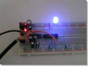
We are going to control RGB LED with a microcontroller. Using Pulse Width Modulation (English: Pulse Width Modulation or PWM), we can digitally analog signal opwekken.Ik have used a software PWM. This is thus applicable to PIC’s with and without hardware PWM. The LEDs are connected directly to the pic outputs without ballast resistors. This is possible because the outputs are limited to a maximum of 25mA internally.
a MAX232. For a first test, this is not necessary and can be omitted initially. If one wants the colors without herprogrammerren reprogram the microcontroller then the RS232 interface is required If we connect an LED to a square wave with a 100Hz PWM of 50%, the LED will be 50% of the time and 50% off. This can people not see with the naked eye. It’s just too fast. By now setting the PWM 0n 25% LED, 25% of the time and 75%. We only see that the LED is lit. Less bright With this technique we can led to full (PWM = 100%) to completely (PWM = 0%) control.
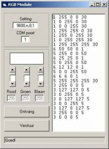
VISUAL BASIC RGB LED DRIVER INTERFACE
Program LED color according to the codes sent over the timing of the transition period is determined transition format for burning different codes given 23 units also conducted and PWM color variants statements of the Company for the description of shared
Controlling RGB LED using a PIC 16F628. Purpose of the project: An RGB LED multi color burn. Back to the beginning. What is an RGB LED. This is basically not one but three separate LEDs LED 1 enclosure. The 3 separate LEDs have the same 3 colors as a pixel of a TV. Hence the name R ed G reen-B lukewarm. The LED that I use has 1 – connection (say RGB) a 3 + connections (say + R, and + G + B).
PIC16F628 PWM RGB LED DRIVER TEST
source: members.upc.nl Computer-Controlled Programmable RGB LED Driver PIC16F628 PWM schematic source code files alternative link
Hexadecimal and binary counter display LED display applications have been realized with all circuits PIC16F84A isis simulation code and other files are MPLAB Hex-button controlled adesimal Counter 1-2-3-4-5-6-7-8-9-cross count ABCDEF. Dip switches controlled display hexadecimal display counter circuit based… Electronics Projects, Hexadecimal, Binary Counter Circuits LED Display PIC16F84 “microchip projects, microcontroller projects, pic assembly example, pic16f84 projects, picbasic pro examples,
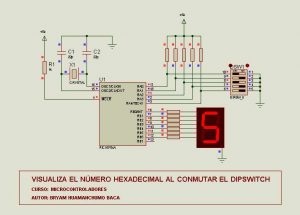
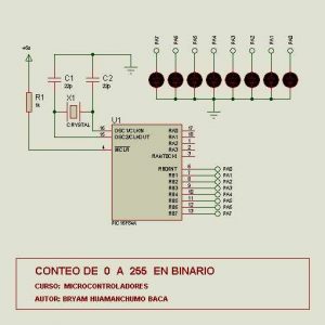
Hexadecimal and binary counter display LED display applications have been realized with all circuits PIC16F84A isis simulation code and other files are MPLAB
Hex-button controlled adesimal Counter 1-2-3-4-5-6-7-8-9-cross count ABCDEF. Dip switches controlled display hexadecimal display counter circuit based on the combination of numbers will appear on off, Automatic 7-segment display hexadecimal display counter applications, 0-a-255 Binary counter with LCD display picbasic pro sample
LED 6 digit display for rig frequency counter -Just as it may seem at frequency display of rig, and produced a dot LED-PD4435 counter, and make use of this in the future, and that the “sold out, there is… Electronics Projects, PIC16F84 LED Display Frequency Counter Circuit “microchip projects, microcontroller projects, pic16f84 projects,
LED 6 digit display for rig frequency counter -Just as it may seem at frequency display of rig, and produced a dot LED-PD4435 counter, and make use of this in the future, and that the “sold out, there is no plan of the re-arrival” and. To give up this, I made a 6-digit display using the 7-segment LED.
7 segment LED 6-digit precision TCXO 12.8MHz (1ppm), PIC16F84 with 1MHz ~ 300MHz (400MHz) IF offset frequency counter. TD7104P (Prescaler ÷ 8, ÷ 1) +2 SC1906 later in the preamp, PIC 16F84A-P20 count, LED display TC4511 drivers. Left; 144.90MHz handy 200mW transmission. ANT of the counter, lead 5cm yellow alignment there. And Central; 7,649.1 kHz SG signal. Minimum digit 100Hz. Zero blank function put, unnatural 0 of top disappear. And right; at 33.1688MHz, it is not. 433.17MHz handy 200mW transmission.
PIC16F84 FREQUENCY COUNTER PROJECT
The first stage prescaler counter TD7104P (÷ 8). Single power of PIC16F84A-P20 is, 433.17 ÷ 8 = 54.14MHz. However, close to 10kHz stand, display varies the limit. Only minutes to display low 1.2kHz, you’re counting mistake. If shaped by CMOS-TTL input waveforms of PIC, and extends to 60MHz or more probably.
Source: saturn.dti.ne.jpPIC16F84 LED Display Frequency Counter Circuit schematic pic assembly source code files alternative link:
2 Application There pic16f626 application with PWM and LED lasts probably a variety of effects there proteusd the need to try the other simple series-connected LEDs and for limiting resistance is made up of various colors (blue LEDs, green… Electronics Projects, For Car Led Neon Circuits “led projects, microchip projects, microcontroller projects,
2 Application There pic16f626 application with PWM and LED lasts probably a variety of effects there proteusd the need to try the other simple series-connected LEDs and for limiting resistance is made up of various colors (blue LEDs, green LEDs, white LEDs) LEDs used
PIC12F629 LED NEON PROJECT
This option LED neon electric site is completely the same as for construction of LED neon, but what is covered is light emitting diode lenses Ice but only so that they are opaque and do not create circles This is carried out zbroušení finest abrasive paper (280 or 1000) under ground water (ustridnete a little square abrasive paper, dip it in water and gently grindstone led diodes – just as 5x probrousit around the lens so that the lens LEDs is not clear but watt = variance light It is very simple. Srdcem je mikrokontroler PIC12F629 (IC2). The heart is a PIC12F629 microcontroller On its inputs GP1-5 are connected to the land of individual buttons (TL1A + TL1B … TL5A + TL5B)
LED BACKLIGHT CAR USING LED NEON
Source: chrudim.czLED Neon project alternative links
AT89C51 Scrolling LED Circuit Operation: Keypad’t the values entered the program through is continually monitored, “*” key is pressed unless the display of the first letter that section required all letters appear, but the desired letter or number after… Electronics Projects, AT89C51 Keypad Controlled Scrolling LED Dot Matrix Text “8051 example, avr project, keil example, microcontroller projects,
AT89C51 Scrolling LED Circuit Operation: Keypad’t the values entered the program through is continually monitored, “*” key is pressed unless the display of the first letter that section required all letters appear, but the desired letter or number after it is written “*” key is pressed, the entered character sequence element is recognized as a scanning begins again for the next element. Meanwhile, in the LED is fixed, and the entered character which character is seen is entered.
A number of letters in the program is defined in the source code. Up to 20 characters can be entered with the keypad; 20 characters all if entered shifting process automatically start their own are more or less the quantity which character is entered after the # key is pressed, if the scrolling function is activated and characters that are written from right to left starts to slip.
SCROLLING LED TEXT SCHEMATIC
AT89C51 Scrolling LED project keil source code and proteus isis simulation schematic proteus ares PCB desing;
Used microcontroller PIC16F84A four different study program on 8 leds switch is turned off, the program begins to work every key LEDs in different ways combustion provides all the source files proteus isis simulation. DSN ares pcb. LYT PicBasic…. Electronics Projects, PIC16F84A Four Programmed LED Animation Circuit “led projects, microchip projects, microcontroller projects, pic16f84 projects, picbasic pro examples,
Used microcontroller PIC16F84A four different study program on 8 leds switch is turned off, the program begins to work every key LEDs in different ways combustion provides all the source files proteus isis simulation. DSN ares pcb. LYT PicBasic.
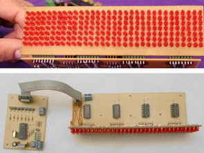
Without the use of ready-made modules connected in parallel circuit pic 16F628 36 leds for power output will not be sufficient 2N2222A NPN transistor output circuits powered by regulated the supply of L7805 is provided by In addition to… Electronics Projects, PIC16F628 PICBASIC PRO 36 LCD led matrix “microchip projects, microcontroller projects, pic16f628 projects, picbasic pro examples,
Without the use of ready-made modules connected in parallel circuit pic 16F628 36 leds for power output will not be sufficient 2N2222A NPN transistor output circuits powered by regulated the supply of L7805 is provided by
In addition to the letters you want to have a computer program to create the shapes of the LEDs will start flashing speed, etc. from which direction. oluşltur’s settings after the desired icon, click on the Generate File C: \ directory file is created in sans_nom.thı.txt ldate have codes, these codes are contained in the file will be replaced with ledthı01.bas
Dll for the program to work vbrun60 SP5 content of the package to be installed if necessary Advpack.dll, ASYCFILT.DLL, comcat.dll, Msvbvm60.Dll, OLEAUT32.DLL, OLEPRO32.DLL, STDOLE2.TLB, Vbrun60.inf, W95inf16.dll, W95INF32. DLL due to all exe files are automatically installed packages.
Source: users.picbasic.org/projects/FANCY%20LEDS/fancy_leds.htm PIC16F628 PICBASIC PRO 36 LCD led matrix alternative link:
High power lamp control Maximum lamp brightness preset Minimum lamp brightness preset for filament preheating Automatic or manual dimming between brightness presets Separate flash on and flash off Flash brightness preset Dimming rate programmable from instant through to 40… Electronics Projects, Two-Channel Dimmer Circuit with PIC16F84A LED Level indicator “microchip projects, microcontroller projects, pic assembly example, pic16f84 projects,
High power lamp control Maximum lamp brightness preset Minimum lamp brightness preset for filament preheating Automatic or manual dimming between brightness presets Separate flash on and flash off Flash brightness preset Dimming rate programmable from instant through to 40 seconds A and B dimming rate selection Lamp brightness indication Automatic dim up and dim down indication
Large size also display the prices are expensive, but they also have a limit if you make yourself big size LED display can achieve. Led diplay pic16f876 used in the control circuit of the LEDs are driven by uln2803… Electronics Projects, Large 7-Segment Display Circuit ULN2803 PIC16F876A “ccs c examples, microchip projects, microcontroller projects, pic16f876 projects,
Large size also display the prices are expensive, but they also have a limit if you make yourself big size LED display can achieve. Led diplay pic16f876 used in the control circuit of the LEDs are driven by uln2803 software ccs c prepared by the working frequency of 20MHz.
ULN2803 PIC16F876A BIG 7SEGMENT
PIC16F876A to be used to control all of task on this project.You can replace with any 28 pin PIC microcontroller.PortB set as output to drive all segments.PortC set as output to drive each digit ULN2803 which is octal hight voltage high current darington transistor array The example firmware included in this project is 4digits counter writen for CCS C compiler
Source: goo.gl/RaZIqLarge 7-Segment Display Circuit alternative link:
In this project, I PIC16F84A microcontroller PORTB bits to 0 (RB0) LED (light emitting diode) is connected. In the project, this LED is extinguished and burned at intervals of 250 milliseconds. was operated with a 4MHz crystal microcontroller. RB0… Electronics Projects, PIC16F84 Simple LED Blink PIC-C “led projects, microchip projects, microcontroller projects, pic16f84 projects, simple circuit projects,
In this project, I PIC16F84A microcontroller PORTB bits to 0 (RB0) LED (light emitting diode) is connected. In the project, this LED is extinguished and burned at intervals of 250 milliseconds. was operated with a 4MHz crystal microcontroller. RB0 port (pin 6) is connected to a resistor and an LED.
PIC16F84 LED BLINK SCHEMATIC
PIC16F84 LED BLINK CODE
/*--------------------------------------------------------------------
*
* 	LED Blink PIC-C
*	===========================
*
* Yazan: Dogan Ibrahim
* Tarih:   Mart 2003
* Dosya: PROJE1.C
*--------------------------------------------------------------------
*/
#include <pic.h>
#include <delay.c>

main(void)
{
TRISB = 0;			// PORTB bits do outputs

for(;;)				//continuous loop
{
RB0 = 0;		// LED OFF
DelayMs(250);		//250ms wait
RB0 = 1;		//LED ON
DelayMs(250);		//250ms wait
}
}
A very simple application is carried out with the PIC16F84 PIC programming can be useful for beginners People Summer program after program with MPLAB ASM extension Alt + F10 on the keyboard and save when you press Go MPLAB… Electronics Projects, PIC16F84A Simple LED Ciruit “led projects, microchip projects, microcontroller projects, pic assembly example, pic16f84 projects,
A very simple application is carried out with the PIC16F84 PIC programming can be useful for beginners People
Summer program after program with MPLAB ASM extension Alt + F10 on the keyboard and save when you press Go MPLAB ASM code translates into HEX codes (they say). If there are errors in the ASM code you ERROR command shows errors. When you double-click ERROR command shows the incorrect line. After correcting errors in the compilation process is done again. After the compilation process of the program HEX codes are registered, where the ASM code occurs.
RGB LED control circuit 16F628 microcontroller based on the software prepared by JAL. Source code and circuit diagrams are available. According to information from the computer via serial port LEDs working with Visual Basic code for the application of… Electronics Projects, PIC16F628 RGB LED Control Circuit “led projects, microchip projects, microcontroller projects, pic16f628 projects,
RGB LED control circuit 16F628 microcontroller based on the software prepared by JAL. Source code and circuit diagrams are available. According to information from the computer via serial port LEDs working with Visual Basic code for the application of resources given the necessary programs.
RGB CONTROL CIRCUIT DIAGRAM
This code is for a simple RGB LED controller for 8 LEDs using a PIC16F628. It is controlled by sending 3 bytes to the internal USART for the red, green, and blue color channels. The operation is very simple and so is the wiring. The PIC selects each LED then turns on/off the respective colors then goes to the next LED. Because of persistence of vision, the eye sees the LEDs as all being on at the same time.
Source: http://www.semifluid.com/?p=12 PIC16F628 RGB LED Control Circuit Alternative link:
FILE DOWNLOAD LINK LIST (in TXT format):LINKS-569.zip
PIC16F84, PIC16F628, PIC18F452 circuits made with 16 32 60 Column Marquee isis proteus simulation files are one of many circuits can simulate. Source codes and codes on the circuit’s writing projects can be done by modifying the different advanced… Electronics Projects, Scrolling LED Text Circuits PIC16F84 PIC16F628 PIC18F452 “microchip projects, microcontroller projects, pic16f628 projects, pic16f84 projects,
PIC16F84, PIC16F628, PIC18F452 circuits made with 16 32 60 Column Marquee isis proteus simulation files are one of many circuits can simulate. Source codes and codes on the circuit’s writing projects can be done by modifying the different advanced rock. Thanks to those who contributed to preparing
Made with 32 column marquee 8X32 PIC16F628 pic basic Keyboard Controlled assembly 24 columns marquee with PIC16F84 PIC18F452 pic basic 60 column marquee PIC16F84A 8 × 17 + 112 LEDs LED marquee assembly PIC16F628 with 16 column marquee c language Marquee Display assembly with PIC16F84 16
Scrolling LED Text Circuits all files:
FILE DOWNLOAD LINK LIST (in TXT format):LINKS-84.zip
Some time ago I bought some Electric Tea Lights that are charged using a wireless charger. This charger has a power LED that shows when the Lights are charged. After 10 hours of charging the charges switches off. It seemed, however, that there is an issue with the charger since the power LED that shows if the charger is active is always on, albeit a bit brighter when it is charging but this is hardly visible. In fact, you can hardly see if the power LED is on at all. I mentioned it to the manufacturer and I received a new charger but it had exactly the same problem
So I wanted to create something that shows if the charger is active when I need to charge my new Tea Lights. Of course I could try to replace the LED in the charger but I did not want to open it because of warranty issues. I had some older Tea Lights that no longer worked due to the battery being too old and my idea was use such a Tea Light to show that the charger is active by putting this Tea Light in one of the locations where the Tea Lights are charged.
I could have made a simple on-off Light but since it is Tea Light which normally has a candle effect, I decided to give it a candle effect too. I used the housing and the coil of an old Tea Light and created a candle effect using a LED and a PIC microcontroller. Instead of a PIC you can of course use an Arduino.
Step 1: Required Components
You need to have the following components for this project:
A piece of breadboard
PIC microcontroller 12F615
Diode 1N4148
47 uF/25V electrolytic capacitor
100nF ceramic capacitor
33k and 470 Ohm resistors
Orange LED
The housing and the coil of an old Tea Light
See the schematic diagram on how to connect the components.
Step 2: First Some Analysis
Before I started the project I needed to know if the coil in the Tea Light would provide sufficient power for the circuit to work. I connected an oscilloscope to the coil when it was in the charger. The output of the coil is shown in the screenshot.
The charger generates a pulse with a frequency of about 36 kHz and generates a voltage in the coil of about 8 Volt peak. In the schematic diagram this signal is rectified with the Diode and Electrolytic capacitor. Some measurements gave the following results:
Without any load the rectified supply voltage is around 6.6 Volt
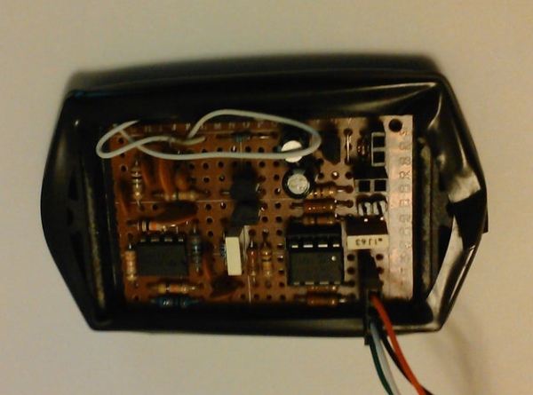
When connecting a LED and a resistor, drawing a current of 13 mA, the supply voltage drops to about 4.7 Volt. The photo shows a setup of this test.
These measurements showed me that it was possible to supply the circuit since most current goes through the LED and not the PIC.
Step 3: Building the Electronics and the Tea Light
First you need to remove the bottom part from the Tea Light using a small saw. Be careful since you might damage the coil if you saw too deep. The pictures show the saw I used and the result with the bottom plate removed.
The only parts you need are the housing and the coil.
You can build the circuit on a breadboard that has the size of the original electronics. In the picture you can see the circuit as I build it on the breadboard and how it fits in the housing of the old Tea Light.
After assembling and testing the circuit you can glue the bottom part back to top part of the housing.
Step 4:
As already mentioned, the software is written for a PIC12F615. It was written in JAL. Since I did not use any specific libraries the total code size is only 165 bytes which fits easily in the 1k program flash memory this specific controller has.
To create a candle effect I use Pulse Width Modulation (PWM) to vary the intensity of the LED. Pulse Width Modulation has been described several times, e.g. in this Arduino Article: https://www.arduino.cc/en/Tutorial/PWM
PIC and Arduino have special PWM hardware on board that makes it simple to generate this PWM signal. A Timer is used to create the PWM period and a register is used to vary the on-time of the LED during this period of time, the so called pulse width. In this project the PIC runs on an internal clock frequency of 4 MHz, generating a PWM period of 4,1 ms which equals a frequency of 244 Hz. This frequency is not visible for the human eye. The main program increases and decreases the pulse width randomly which creates the candle effect.
The JAL source file and the Intel Hex file are attached.
The video shows the operation of the Tea Light. When the charger is switched on, the Tea Light starts flickering. Since there is no battery in the Tea Light it stops as soon as the charger switches off or when the Tea Light is removed from the charger. As you can see in the video, the light from the power LED is hardly visible. The good thing is that it resulted in this nice project.
Have fun building your own project and looking forward to your reactions.
LED screens are everywhere. Chances are you’re using one to read this right now. With the release of Digilent’s PmodOLEDrgb, now you can program one yourself!
Copy the “OLEDrgb” folder into your Documents>mpide>libraries folder. If this folder doesn’t exist, open up MPIDE to automatically generate the folders.
Once it is copied, restart MPIDE and click the Open button. You should see OLEDrgb in the drop down menu.
This PmodOLEDrgb library contains several useful functions that make interfacing with the PmodOLEDrgb much simpler. It takes care of all of the timing and individual SPI transmissions that happen between your board and the Pmod.
Step 3: Plug in the PmodOLEDrgb
The library requires that the PmodOLEDrgb be connected to DSPI0 on your PIC32. On the chipKIT Pro MX7, this is found on Pmod port JD. Plug your PmodOLEDrgb into port JD.
Step 4: Create a New Sketch
Click Open, go down to 1.Basics, and open the BareMinimum project.
Go to File and click Save As. Name and save it.
Step 5: Include and Instantiate
Next up, we need to include the necessary libraries. Add the following lines to the beginning of your program.
#include <DSPI.h> #include <OLEDrgb.h>
Oledrgb OLEDrgb;
This will include the SPI and the OLEDrgb libraries, and will instantiate an Oledrgb object named OLEDrgb.
Inside the setup() function, add the following line:
OLEDrgb.begin();
This function goes through the powering on sequence and configuration that the PmodOLEDrgb must go through to operate correctly.
Step 6: Using the Library Graphics Functions
You can find several functions within the OLEDrgb.c file included in the library. These functions include DrawPixel, DrawLine, DrawRectangle, and DrawBitmap. There is also a helper function called BuildRGB(red,green,blue) that formats the RGB color into 2 bytes that can be read by the PmodOLEDrgb.
Calling OLEDrgb.DrawPixel(50, 15, OLEDrgb.BuildRGB( 255 ,0, 0)) will draw a pixel at coordinate (50,15) colored red.
Calling OLEDrgb.DrawLine(10, 20, 45, 5, OLEDrgb.BuildRGB(0, 255, 0)) will draw a line from (10,20) to (45, 5) colored green.
Calling OLEDrgb.DrawRectangle(10, 20, 80, 60, OLEDrgb.BuildRGB(0, 255, 0), true, OLEDrgb.BuildRGB(0,0,255)) will draw a green rectangle from (10,20) to (80,60). True signifies that it will be filled in, and the last parameter sets that the fill will be blue.
Plug your chipKIT Pro MX7 into your computer via UART and select it in MPIDE by clicking Tools>Board>chipKIT>chipKIT Pro MX7. Select the serial port that your board is plugged into by clicking Tools>Serial Port>COM_. Once you are all set up, click the Upload button to upload it to your board.
Step 7: Displaying a Bitmap Part 1
Displaying a bitmap using the OLEDrgb library requires us to first turn it into a byte array. I created a python script that does this, but first we need a bitmap.
Open paint and click on Resize. Resize the image to 96 pixels horizontal by 64 pixels vertical.
Let your imagination run wild. When you are finished, save the image as a 24-bit bitmap.
Copy the bitmaptoarray.py script into the same folder as your masterpiece and run it. When prompted, enter the name of your bitmap file and press enter. If it worked you should see “Byte array created as masterpiecearray.c!” Within your folder, you should see a new .c file that contains your array.
This will draw your masterpiece array from (0,0) to (95, 63) when your program is run.
Click Upload to program your board. You should eventually see your masterpiece on the PmodOLEDrgb!
Step 9: Snake!
For a more advanced example, check out the SnakeRGBLED sketch included in the OLEDrgb library. It requires a PmodBTN, or at least a 4 button setup on Pmod port JF.
This example does a couple of cool things with the PmodOLEDrgb. The title screen features a snake that sticks its tongue out periodically. This is done by loading several different frames using the DrawBitmap function. The game itself uses a scaling algorithm to scale a 48 by 32 grid onto the 96 by 64 OLED. Better yet, you get to play Snake!
I made this computer controlled traffic light for my work to show the status of the software being build, but I will spare you the details. This was also my first home project with a PIC controller.
The traffic light is using an old Ikea traffic light meant for in childrens bedroom. It has switches behind each light with which you can turn on and turn of the lights. After modification, all switches and lamps are removed and the lamps are replaced by 12 Volt LED lamps. Control of the traffic light is done using a PIC controller and a – yes very old but very easy to use – RS232 serial interface. Reason for using this interface is because the PIC has it on board and it requires only an RS232 driver IC to get the interface operational. Via a simple protocol, each lamp can be individually controlled from on to off to blinking. Since the traffic light is used for representing the status of a build, the traffic light turns off automatically if it is does not receive any control updates within 10 minutes. So in order to keep the traffic light alive, the status of the lamps must be updated frequently.
This is my first Instructables post so I hope the information is sufficient to build it yourself.
Step 1: Remove the Internals and Install the LED Lamps
Remove all switches and the holders for the lamps. After that, install the 12 Volt LED lamps. The LED lamps are the ones that you normally use to replace 12 Volt AC halogen lamps. In our case the LED lamps are connected to 12 Volt DC which is working fine. The lamps are soldered on a breadboard which is glued to the place were intially the old lamps were mounted.
Step 2: Build the Electronics
The electronics is based on a PIC 16F1823 controller and is assembled using a bread board. As power supply an external 12 Volt DC adaptor is used.
The attached Intel hex file can be used to program the PIC controller.
Since the LED lamps can be quite bright, the brightness can be lowered by removing the brightness jumpers, see the schematic diagram.
The default baudrate settings for R232 communication are 19200 baud, 8 bits no parity and one stopbit. With a jumper, the baudrate can be set to 9600 baud. The MAX232 IC is used for driving the RS232 connection.
The ‘Alive’ LED blinks with a rate of 1 Hz and shows that the traffic light is operational.
The 9 pin female RS232 D-connector is mounted on the back of the traffic light, see picture. When a connection is made to a computer, a non-twisting cable is needed.
Since RS232 is quite old and laptops do not have this interface anymore, use an USB to RS232 adapter.
Step 4: Connect It All
The electronics are connected to the LED lamps and the RS232 connector. The bread board can easily be mounted via some bolts but do not forget to make holes in the bread board for the bolts so that the bread board can be mounted.
Step 5: Operate the Traffic Light
The traffic light can be tested using the protocol given in the attachment. You can use a simple terminal emulator program like ‘Termite’ to control the traffic light but you can also use the attached test program ‘Verkeerlichttest’ (sorry is in Dutch). Note that you need to have .NET installed on your computer in order to run this test program.
I want to acknowledge that so many here contributed ideas and support, and although there are too many to name now, I did want to acknowledge my gratitude for all that contributed to the project. I am so happy that the printed circuit boards I developed helped those that wanted or needed them, whether they had put in months of work, and just couldn’t get the circuit working,just wanted to eliminate all those wires, wanted a PC Board but didn’t know how to design them, designed a circuit board and then realized how expensive they can be to have fabricated, didn’t know how to read schematics, were up against a school project deadline, or just loved the added features like the music input and remote control – I am happy that so many were able to benefit from them.
I myself was so taken with the original project, that if I didn’t have the knowledge or skill or resources to design a PCB, or wire up the circuit myself,I would have gladly bought a board if they were available. Unfortunately, none were in theoriginal instructable by CHR when I had first seen it. If you couldn’t hand build it, you were on your own, and I felt very sorry for those that tried and failed, or didn’t even know where to start.
PLEASE DON’T ASK FOR EAGLE FILES for the PCBoards. It wasn’t designed in Eagle, so there aren’t any.
Now…on to the instructable.
I was immediately enthralled with the LED Cube instructable by CHR . I am going to give a piece of advice I saw there that made a lot of sense. READ EVERYTHING including all the comments. Often there is information and answers to questions that may answer a question you might have.
I thought “I COULD MAKE THAT” (and I did, making little improvements along the way) – but I took it a step further, and decided that I would try to make it so that almost anybody could make it as long as they could solder and could tell the difference between the different parts. That is the reason I created the PCBoards to control the cube, and eventually even a Cube Base Board which all but eliminates the point-to-point wiring from the project. I loved the project but hated all the messy wires everywhere. I have also supplied demo code (both the original code and many of my modifications), and clickable AVR initializer and code uploader utilities to get the code onto the board quickly and easily for those that aren’t comfortable with dos-prompt based utilities like AVRDude. There is also a pinout / connection chart that you can use to design and troubleshoot your own board using the Arduino, ATmega328P, or the more capable ATmega32 microcontroller for extended functions.
The hardest part is building a cube that is straight and square. I will be addressing this first. If you use my construction methods, your cube should be as straight and square as in photos above.
I have a good electronics background, so I immediately wanted to build one of these cubes the second I saw it. The more I got into it and read the comments on hiswell documented instructable, the more I thought I might be able to help people with less of an electronics background understand exactly how this thing actually works, and troubleshoot problems. People were asking all kinds of questions long after people that really knew the circuit stopped answering them, and I found myself answering questions in his instructable on a fairly regular basis. Finally, I knew enough to make what I hoped would be an easier to understand instructable. Not only that, I have made a few improvements along the way as well, and eventually even PC Boards for myself, and got extras for those that might also want them
As I start out, I realize I will be “winging it” a lot here, so forgive me if I am unclear at any point, and feel free to ask questions. If you see ANODE written where you know it should be CATHODE – or vice-versa – let me know. Sometimes I get tired when writing and get electronic dyslexia, and mix them up. I have tried my best to proof read my instructions to make sure this hasn’t happened. Try to keep in mind during construction that there is one cathode connection per layer, and 64 anode connections.
I will ask however that if you are getting ready to build one of these, Especially if you want to build your own circuit, that you go through CHRs well documented instructable FIRST, and then read through this one.
Try to build his controller circuit if you can, and feel free to contact me if you run into trouble (which almost everyone does). THIS can be a VERY daunting task. Many people find they can build the physical cube, and are able to solder connections easily enough, but when it comes to constructing the actual circuit, that’s where it all usually falls apart. Troubleshooting a point-to-point hand wired circuit is not easy, even if you know what you’re doing. FEAR NOT ! As this instructable progresses, I will be working on a number of circuit boards that will include features requested by people here, and at varying levels of soldering expertise all the way from simple through hole soldering to completely surface mount technology boards. You will be able to purchase these boards when they are available, and prices drop as more requests for boards come in due to volume discounts. Just don’t expect them to be five bucks – I won’t be mass producing them which makes my cost a lot higher. Watch for board revisions if you have made a recommendation or request for a board feature that I liked
Music triggered modes for those with my circuit boards… (I’ll be working on more as suggestions come in) – LATEST CODE IS NOW posted on STEP 10
Sorry about the video quality on this one, but I was in a hurry to get these posted and didn’t take the time to adjust the camera well.
Just hit the MUSIC button on your board (Black Edition V3.5 and higher, ARMS series or RAMP series) or wireless remote (ARMS and RAMP series boards only) to cycle through the music modes. Previous 5 mode code is on STEP 12 so you guys with the new boards can play with it! I will be adding to it though! The code works with both wired input as described in step 17 ,built onto the board (RAMP boards only), or using the Mic Module in the parts list (3.5A and above, ARMS or RAMP boards)
If you are thinking “Big deal, I have seen cubes react to music in other videos” – well, we are doing it WITHOUT a PC hooked up to the serial port! That’s right, the ATmega32 is doing this on it’s own. What is more, with the Mic module option, this means you could take your cube to a party and set it somewhere (that nobody can touch it) and let it react to the music without even hooking anything up to it.
This instructable has mutated over the past few months, and you’ll see a bunch of end results before we get into how to make the cube, and the improvements that have been made over the original construction techniques and original circuit, as well as improvements made on the PC Boards over time.
A couple quick videos of my cube in action are above. The first video is the cube as a standalone device, and the “Cube Perry” video is under PC control via the TTL Serial port and a script written in Processing. The serial port is key to allowing it to be controlled by things like a PIC, another Arduino or PCDuino or PC computer .
Stand-Alone Music Input! The video below demonstrates this addition to the circuit,
The schematic is on step 17 for connecting an audio source to previous board versions.
By the way – come back here every few days to check up on this instructable. I tend to add to it without notice! This includes additions and revisions to the code.
If you have tried to make your own controller – or just know you couldn’t build one from scratch, but COULD solder a PC board, then ask me about what boards are available.
Send me a private message for details.
NOTE: If you downloaded the 5 mode music hex file before Jan 12, you need to download the latest code. The music modes originally used up a little too much RAM in the AVR, and when the Fireworks effect would try to initiate, the cube would reset. This has been fixed by reducing the firework sparkles from 60 to 40. The new 5 music mode HEX file does not have this problem now when running in animation mode. Fortunately I first ran into this issue with the Arduino when porting over the same routine. Since the fonts go into RAM rather than EEPROM on the ATmega328p, there was a lot less RAM to utilize, and this is why there are only 30 sparkles in the fireworks routine that was ported to the Arduino portable code.
The ARMS and RAMP series boards have an area marked off where the wireless remote module goes. If you are NOT going to use the wireless remote module, none of the parts in that area need to be put on the board, and you don’t need to purchase the remote module. Likewise, if you don’t want acoustic music response, you don’t need to purchase the Mic module.
And now on to our regularly scheduled program (How To Make The LED Cube)
Step 1: There’s Got to Be a Better Way…OR “Building the Perfect Cube”.
I hated how hard it was always to align the LEDs when soldering them together though, and thought “THERE’S GOT TO BE A BETTER WAY” … but HOW?
I thought “If the LED leads were on the edge of the LED, it would be a snap to line them up. So it hit me…MOVE the anode to the outside of the LED. If the anode coming from the LED above was on the outside edge, the LED below could sit directly under the LED above it. And if the legs were on the outer perimeter, they would line up easily to be soldered. Not only that, it takes care of measuring because if you solder the leads at the point where they meet, it would always be the exact same distance every time! So I started bending the leads in this manner, but I was soon suffering from finger fatigue, and it was hard to make the bends precise. Once again, I was thinking there had to be a better way. I tried to think of how a machine programmed to do this automatically would work, and how I could emulate that machine manually. After much thought, I had an idea.
So I made a small jig out of an old X-Box heat sink, but you could use almost anything you can drill a precise hole into that won’t easily wear.
Drill a hole the exact size of the LED you are using. If the hole does wear or is a bit big, stick some tape over half the hole, and shove in an LED, and then stick the tape down good. The LED will bring the tape inside the hole and make it a tighter fit. Once the tape is nice and secure, remove the LED. You want the fit to be snug, but not so tight that it’s hard to remove the LED. Mine would be snug enough that I added an aluminum “eject” lever as well to help pop the LEDs out of the jig. I tried to loosen the hole up a bit, but then had to add tape because I widened it too much! LOL. Wnem I moved up to the “hat top” LEDs, sticking in the hole no longer seemed to be an issue.
Step 2: The Better Way…put Away the Tape Measure.
BEFORE YOU START – make sure the leads (legs) on your LEDs are 27 and 28mm or 28 and 29mm in length. If they are shorter, your cube will be too small to use on the base boards you can get from me. The sellers in the list of links to cheap parts guarantee that you get the long lead LEDs Also, if you simply build the cube smaller and make your own base, if the leads are the 17mm ones, you may find that you cannot see the LEDs in the back well, and animations that go all the way through the cube won’t look right because too many LEDs are in the way of the ones behind them. If your LEDs are too short, see if the supplier will exchange them, but it’s best to check before paying for them first.
So the trick here is to take the Anode, which sits underneath the LED, and bend the anode out so it is at the outer edge of the LED. This means that the Anodes will all line up perfectly underneath each other when you go to solder them. I won’t lie to you, this goes against what manufacturers and others will tell you about bending the leads on an LED because of the risk of damaging the LED in the process – however I have never damaged more than I can count on one hand building a cube this way.
The LED goes in the hole you drilled in your bending jig with the anode away, cathode close (anode opposite side from you, cathode closest to you) when you insert it in the hole. Once the LED is firmly in place, bend the cathode directly to the right til it’s horizontal. bend the anode straight forward (away from you) til it’s also laying flat. use snub nosed pliers and slide them down the anode til they JUST hit the outer edge of the LED (the LED’s rim should be sticking above the aluminum block if the hole is fitted correctly, and you want the pliers to STOP at the rim of the LED). Grip the anode, and bend straight back up, making sure the part against the LED stays against the LED by applying downward pressure as you make the bend – meaning the anode should now be in an “L” shape, with the lower part of the “L” going from the edge of the LED to it’s origin under the LED. The LED is now ready to be soldered into it’s layer – but for now, put it in a pile/box/bag with the rest of your pre-bent LEDs. Don’t forget that down one side (the right side) of the layer, you will want the cathode bent from the edge of the LED into a laying down “L” shape with the long top of the “L” pointed towards you (t’ll be an upside-down L, or a “7” if you will) so that the row it is in can connect to the row below it. These will interconnect the rows in the layer down one side of the layer, and the last LED will have it’s lead sticking out the end of the layer (unmodified from the way it was originally bent). This will be a convenient place later to connect the layer select line from that layer’s transistor. NOTE: these leads when bent may not meet the ones they need to connect to. If you need to, add some wire or cut-off resistor leads or something to bridge the gap when you go to solder them. Making a solder bridge is not a good idea as you may overheat the LED and cause it to fail. Also solder bridges can be weak, and break later.
In the magnified view, you can see how the anodes line up perfectly when soldered together in a column. You solder them where they MEET when joining one completed layer to another – DO NOT overlap them at all. This way you don’t have to measure anything because they will always meet at the length of the anode from the outer rim of the LED. This means perfect spacing if the LEDs are bent properly.
Step 3: Assembly of the Cube – Layers First!
This goes pretty much as CHR’s assembly, just with my improvement on how to bend the leads. PLEASE CLICK ON THE SMALLER PHOTOS so you can read the notes on them. If you don’t click the photos, you will miss the attached notes !! The other thing I did out of laziness, and lack of carpentry skill, was to use cardboard for the rig to solder the layers together. Since my leads were 28 and 29 mm long…I figured take off a mm for bending, and maybe one more for good measure. Well, I forgot to take the 1 more for good measure off, and had problems with gaps when soldering! LOL! The idea would have been (and is), make a grid with 26 mm spacing, and print it out. The cathode leads should meet up when soldering them pretty much perfectly, or with a very small amount of overlap. If your LED cathodes don’t meet up (there is a gap) then make another template and get another piece of cardboard. Print out the template with the grid spacing reduced by 1mm. If you make solder bridges to cover the gap, you may find the cube breaks easily. The other option is to use bits of trimmed off resistor leads or something like that to help bridge the gap. Only do this if the gap is 1mm or less. If the gaps are larger, make a smaller template and start over.
Tape the grid to what will be your cardboard template. I used an old motherboard box. *********************************************************************************************** NOTE: I HAVE NOW INCLUDED A PDF FILE OF THE TEMPLATE GRID FOR YOU TO PRINT OUT *********************************************************************************************** Print 2 copies. You will need 1 for the template itself, and another to make the holes for the cube base.
Poke a pin at each intersection. This is like drilling a pilot hole. I used a large sewing needle. Then find a Philips screwdriver with a shaft about the diameter of your LEDs. Poke this through each hole. The first time you poke LEDs into these holes, they may be very tight when you first insert an LED – don’t worry, the rest of the layers will be easier afterwards. It’s better the holes be a bit too small than too big. CROSS BRACES – you need structural braces on the opposite side that you bent the cathodes down on, and down the middle of each layer. Since I bought 1000 LEDs and only needed 512, instead of straightening out some form of wire for the mid and left braces, I cut the leads off 7 (new unused) LEDs per layer and used the 14 cut leads as support braces. Solder these in place before removing the layer from the cardboard template. TEST THE LEDS BEFORE REMOVING THE LAYER FROM THE CARDBOARD TEMPLATE by connecting negative of your power supply to the cathode grid, and put a 100-330 ohm resistor to your 5V power supply, and touch the other lead of the resistor to each of the 64 anodes to make sure each LED lights. Replace any LEDs that don’t work if the problem isn’t a solder joint.
Once a layer is completed and soldered, and your braces put in place as well and all the LEDs are tested and working, you can poke the LEDs out of the holes from the bottom side of the cardboard. Do it gently and gradually – individual layers are fragile.
I included a photo of one of these layers compared to a spare layer I made for my original prototype cube.
IF YOU HAVE A BASE BOARD:
Put the base board on the cardboard instead of the paper template, and put a needle in two opposite corners to secure it, and poke another needle through each of the holes in the base board through the cardboard to make your “pilot” holes. This will ensure perfect spacing between the pilot holes for your template, and guarantee that the completed cube will fit the base board.
You can see how nicely the layers line up under each other during assembly. No need to try to curve the anodes around to connect to the next layer down. The end result is a near perfect cube. You do need to of course line up each anode so it meets the top of the anode below it while soldering them together. I don’t like joint stress, so I would bend and adjust each lead til it lined up with the lead below it without having to be held in place, then I would solder them together. Line each anode so it just touches the anode below it. This eliminates any measuring or need for spacers to get the same distance from LED to LED (layer to layer) every time.
NOTE: I actually connect the layers with the anodes pointed towards me (cube on it’s side) so that the leads were at the upper edge of the LEDs, making them easy to see and solder (not to the right like in the photo – I just did that because it photographed better that way). The reason I keep saying “the layer BELOW it” is that you build the cube from the top down. Each layer you solder on, is the next layer down once the cube is upright. I found that soldering the layers together while it’s on it’s side, I didn’t require any clamps etc. I would just tack the 4 corner anodes in place, then proceed to solder them row by row.
Also included is a photo of box of pre-bent LEDs. I got into a groove and bent up all the LEDs I would need at one time (plus some), and then I would just pull them from the box and put them in the template to make a layer. It took me about 2 and a half hours to bend enough for the whole cube. I made spares because you do run into the odd bad LED during testing.I find it much easier and faster to test the LEDs once they are bent and soldered in, simply from a time factor point of view.
Testing each LED before soldering it in is pointless, and gives you a false sense that all your LEDs are fine
. Some may fail when you bend the leads, and others may fail from the heat of soldering. You will almost never see an LED fail right out of the box/bag. Bend, solder, THEN test, otherwise you will be testing them before AND after, which is a waste of time, especially when soldering this many LEDs.
IMPORTANT – remember to test each layer while it’s still in the template, before soldering the layer it to the others. I do this by connecting my power supply ground to the layer grid, and connecting a 100 ohm resistor to the positive, and basically sweeping the other resistor lead from anode to anode. This makes for a quick and easy test of all the individual LEDs in the layer. Once the layer is soldered to the cube (the layer above it), re-test it like we did above, then connect the ground of the power supply to the cathode grid of the TOP layer, and touch each anode in the bottom layer to make sure your column (anode to anode) connections are all good. If the anodes aren’t all connected from the current layer to the top layer, the top layer LED won’t light when you strike it’s column with the resistor. IF this happens, then move the ground from layer to layer from the top down until an LED lights. The break will be between that LED and the one above it. IF the LED in the row below the top layer works, but the top one doesn’t, and the solder connection is good, then the LED in the top layer (or layer above the one being tested) may be burned out. test it individually, and replace if necessary.
Some LEDs may burn out during soldering, and some column connections may not get soldered properly, or even may have been forgotten or accidentally skipped when soldering all the connections, or the connection may have broken during the assembly process. If an LED doesn’t light, test it individually in the cube before replacing it – it may simply have a bad or broken or skipped / forgotten solder joint. Make sure you didn’t bridge the LED leads together during soldering if it doesn’t light.
After the cube is completely assembled is NOT the time to find out you have a bad solder joint or burned out LED!!!
Step 5: Make Your Own Base and Attach the Controller Connectors
If you aren’t going to purchase a base board, here is how to easily make your own cheaply!
Make a PCboard or use perfboard to mount a set of two 40 pin connectors to. This allows you to easily connect and disconnect your cube from the controller. I hated the mess of one 8 wire cable per layer running to the control board, plus layer select wires. Again, there had to be a better way.
I figured I needed 64 wires for the anodes, plus at least 8 for the cathodes. I used 2 pins per cathode on the controllers I designed because I was worried about the current – but we now know that’s not really an issue. The design still uses 2 pins per cathode though because it makes it an even 80 pins/wires, and 40 pin connectors are plentiful, and it lets you use old CD-ROM cables to connect the cube to the base. This also accommodates for 40 pin connectors that have one missing “key” pin, because the missing pin is one of a set of layer cathode lines.
NOTE: 40 conductor cables are actually getting more and more rare! if you are ordering IDE cables online, make sure they are 40 conductor and not 80 conductor. Both cables will have 40 pin connectors, but the 80 wire cables won’t work! Check the link in the parts link page to see if the supplier still has 40 wire cables.
NOTE: Many 40 pin male connectors will come with 1 missing pin. This pin will be on layer 2 or 6 depending on which connector. Since the layer pins are doubled though, it won’t actually matter, so you can go ahead and use these connectors anyway. This also applies to cables with one blocked hole where the missing pin would normally be. If your cable has a blocked hole, either open up the hole with an exacto knife, or clip the pin where the blocked hole goes. Since they are layer select lines which are doubled, losing one won’t affect the function of the cube.
I created a standard that I adhere to when wiring these up so I can use any of my boards with any of my cubes. This will let me design other boards using this standard, and be able to easily switch from one controller to another.
Again, not being a carpenter, I turned to cardboard and spray paint for the cube base. I re-printed the same template I printed to make the holes for the LED layer soldering template. I poked holes just as I did for the “pilot” holes into the base with a large pin. I widened them a bit with a much smaller screwdriver than before (not nearly as large as the one I used for the LED soldering template, but large enough that I don’t have to be a machine to get the leads into them). Then poked one more hole for the cathode wires to go through, which I simply ran up one corner of the cube. Remove the template after all the holes are poked into the spray painted cardboard.
Getting 64 leads to line up in the holes was the next challenge – I made a “gaff” out of mechanics wire, but coat hanger or something like it would have worked as well. I bent an “S” at the end of the wire so that I could hook a lead and pull it, or snare a lead and push it to where it needed to go. It took some patience, but eventually each lead found it’s home.
Once EVERY lead was in, I flipped up the cube so it was upside down. Then I would grab each lead from below about half way down the lead with the pliers, and keeping the pliers vertical, pull the lead towards myself until the bottom half of the lead was flat against the cardboard. The lead was now firmly in place and when I hooked it’s column wire to the lead, I would bend the top half of the lead against the bottom half, holding the wire firmly until it was soldered. It’s nice to have the cube be detachable and to not have dangling cables everywhere, so each anode and layer select is connected to it’s appropriate contact on a connector. My cube uses 2 X 40 pin connectors (like for IDE / PATA hard disks) as shown in the photos and discussed at the top of this step.
Once everything was soldered, a little hot glue held the board with the 40 pin connectors to the outside of the cardboard after it was folded closed. The cardboard base itself can then be taped or glued shut.
Eventually I thought there had to be an even better way than this, so eventually I invented Step 14 which is the printed circuit cube base boards. The connectors are aligned perfectly with the controllers so you can cable them to each other or directly connect them together by making one set of connectors male, and the other set female – whichever works best for you.
Step 6: What Goes Where…MAKING YOUR OWN CONTROLLER? YOU NEED THIS CHART!!!
I created this Excel chart which will tell you which pins hook up to where when constructing the controller circuit for either microcontroller. I have found this chart indispensable when designing my own circuits for this project. I actually used this rather than a schematic once I had the chart made up. NOTE: I don’t really discuss the “SUPERTECH HEADER” that is in the Excel chart because during the course of making this instructable, I moved all the components to one board, eliminating the header between the AVR and driver boards completely. I made the chart when everything but the AVR was one board, and each type of AVR had it’s own board that connected via a 26 pin header.
THE EXCEL CHART IS ALSO ONE OF THE BEST TROUBLESHOOTING TOOLS
If things have gone wrong during the construction of your circuit, it gives you an easy reference to do continuity checks with from pin to pin of your components.
If you want to make your own circuit board or hand wire the circuit, you really should make a copy of this! I am also including the schematics from CHR’s original instructable. My PC Boards pretty much adhere to this schematic, with the header and power supply circuits eliminated.
Also, I am including my cube wiring standard for dual 40 pin headers. I find 2 cables so much neater than 9 or more. If you want to use one of my boards and are building your own cube, this is the way to wire it to your connectors.
Because the Arduino (ATmega328) only has the 20 I/O lines we need to drive the cube, some pins serve dual function, because they are not only a cube output, but are also things like TTL Serial lines, or ICSP connector lines. For this reason, you may see some pins listed more than once or a single pin listed with more than one function.
If you are having problems after completing your cube, read these examples, and then go to step 16 for more troubleshooting guides. In the few months I have been working with these cubes, I have either encountered or simulated just about every kind of failure that can happen. If the guides don’t help you, then make a video of your cube running my Power On Self Test. Video it from the front of the cube, meaning the first column to light should be on the left and closest to you. Post the video here or on YouTube, and send me the link. I’ll help you diagnose your issues.
I’ll be using the USBTiny as the example in these troubleshooting tips, because that’s what I have.
NOTE: IF YOUR PROGRAMMER CANNOT FIND THE DEVICE ON ONE OF MY MULTI-AVR BOARDS contact me for the workaround. Some versions of the USBTiny have low current outputs and may fail, but the board can be modified to allow even these programmers to work. RAMP series PC boards will have optional “compatibility jumpers” that you can install IF you have this issue. So far there has only been one reported case, but that was enough for me to change the RAMP series design, just in case it happens to someone else.
If you have a new ATmega32A AVR, and can’t figure out why you can’t upload to the AVR, you may have forgotten to set the fuse bits. Also, if your cube is running slow, you may also have forgotten to set the fuse bits. You onloy need to do this ONCE to the AVR.
Here are the AVRDude commands to set the fuses on your 32A AVR.
NOTE: substitute your ICSP (for example “usbasp”) for “usbtiny” if you have a different programmer Also my clickable initializer MAY not work under X64 windows. I’ll see if there’s a fix for that. Some say it doesn’t work, others had no issues. Nobody has had a problem under 32 bit Windows so far.
You have uploaded the code to the cube – but where it’s supposed to be animating letters, all you get are squares…what gives? >first make sure the font file is correctly compiling. >Then make sure you are actually uploading them to the 32A AVR’s EEPROM.
>Then you can type make install >and it will do it for you. I love being able to just type “make install” and not have to deal with remembering all that syntax. This is the alternative if the clickable code uploader won’t work for you.
>If you like playing with the cube’s code, but don’t have a C language program (I don’t have one either), then use wordpad. If you want to have help with “Did I close enough brackets?” and so on, there’s a nice program called “Programmer’s notepad”. It can help you keep track of those pesky brackets, and a lot more.;
My AVR keeps resetting in the middle of running patterns: >find the furthest component from the power input, and put a 100uF capacitor across it’s power input.
My AVR doesn’t run the script, even though it seemed to upload fine: Make sure you have a pullup resistor on the Reset line. 5-10K is usually fine. Tie it from the Reset line to the 5V. This most often happens to people using an Arduino to run the cube.
Some LEDs aren’t lighting in some patterns, but I know they work because when the whole cube is lit, they light up…WTF?
This is all now covered in step 16 (which didn’t exist during the initial draft of this)
I’ve set the fuses on my AVR, and now it won’t respond: >Once the fuses are set, it selects the external crystal as the clock. >Check your external crystal, and the 22pF capacitors on it. >Try disconnecting the capacitors or replacing them, or replacing the crystal. >Make sure the crystal is on the right pins, and not shorted together or to ground or other pins beside them etc.
Step 8: ICSP (ISP) USB PROGRAMMER BOARD ISSUES.
Ok, I have one of these USBTiny AVR programmers and also a USBasp programmer, and I have had a few issues with both of them. The first confusion that hit me was the whole 6 pin VS 10 pin thing. It turns out they are the same thing – the 10 pin just has extra ground wires to help prevent signal issues at longer cable lengths.
My improvement was to put both headers on one end of the cable.
I also had issues with it disappearing from the OS (Windows doesn’t see the programmer). This seems to be a fairly regular thing. I finally figured out that if I disconnect it from the USB and the AVR (ICSP header on the circuit board), wait about 10 seconds, and reconnect to the USB – wait for it to be recognized and then connect it back up to the AVR, then it’s all good. Just unplugging and reconnecting the ICSP to the USB port rarely corrected this issue if you left the circuit board connected to the ICSP.
If AVRDude isn’t working, there’s a good chance you just need to reset your programmer unless there is a wiring issue.
Oh ya, my green LED on my USBTiny burned out , so I just soldered a regular one over it in case you were wondering why it looks a bit odd..
Pin 3 on the 10 pin is sometimes not connected or used as a key pin.
I have had one person who simply could not program the AVR in circuit with his USBTiny no matter what on one of my PC Boards. The RAMP series boards have Compatibility Jumpers to take care of this issue, and I have a workaround for other boards. Hand built boards won’t have this issue. If you aren’t able to program your AVR in the circuit, contact me, and I can discuss the best way to modify your board to allow the ICSP to work, or we’ll figure out what’s wrong with your circuit.
Step 9: What Do I Power It With ?
The circuit when fully lit uses less than 700mA with most common LEDs on the market. If this sounds wrong because you calculated the current to be something else, you have forgotten that these LEDs are not being driven by DC current. They are actually operating at a frequency of about 744Hz or about 1.42 KHz depending on whose code you are running. This is derived from the 16MHz / 128 prescaler / 21 (or 11) “ticks” per interrupt, / 8 layers. This is good news though. This means we don’t need huge transistors (a 2N2222 will handle 800mA) or huge power supplies. Thus, the answers as to what to power it with are as follows…
Answer #1 – your USB port or portable chargers like my other project here or plug in iPhone/iPad type chargers. I actually power mine off the USBTiny when I am programming it. Anything capable of supplying 3-5V at 500mA or more works fine without a regulator. If you are going to use more than 5V, you need to use the regulator, and if you’ve got one of my boards, you should use a 7.5V input or less. I suggest you get one of these iPod/iPad/iPhone chargers pictured above (the blue cube with prongs). They work great! Either hack a USB cable (cut off one end and attach the 2.1 inch male adapter shown in the parts links) or run it through your programmer via the ICSP connector..
Answer #2 – Batteries. It will actually run off 2 “Triple A” (AAA) batteries, or 2 penlites (AA), but 3 is better (if using one of my boards, regulator needs to be in bypass mode). Do not to use 4 AA or AAA batteries (6V) unless it’s through a regulator. If you are using one of my boards, enable the on board regulator with the regulator / bypass jumper by putting it in the 5.5-9V or 5.5-7.5V position.
If you are using one of my boards, you CAN use a 6V – 9V, but 6 – 7.5 is best because the regulator heats up quite a bit at 9V source through the DC in jack. If your board has a connector marked 3-5V wired input pad, never use more than 5V through the 3-5V connector as it’s unregulated regardless of the jumper. Also ensure that when using more than 5V through the DC IN jack, that the regulator bypass jumper is not in the 3-5V (bypass) mode! The above of course only applies to my AIO and Micro boards above V2.6 and earlier black edition boards.
The less voltage you put in, the less current it draws – and the current drops pretty dramatically as LED current draw with respect to voltage is a logarithmic relationship, not linear. You do lose some brightness around 3.3V, but in reality, it’s hardly noticeable. It uses a surprisingly small amount of power until you get up around 5V or more. So forget what you learned in CHR’s instructable regarding power supplies and power usage. I explain this more in step 13.
Step 10: How Do I Modify the Software? Questions, Answers, and Firmware Repository
This is going to be left as an open forum for specific questions since there are too many aspects of the software to cover in a step, hoping I hit on the one you want to know about.
NOTE: If you downloaded the 5 mode music hex file before Jan 12, you need to re-download the latest firmware. The music modes used up a little too much RAM in the AVR, and when the Fireworks effect would try to initiate, the cube would reset. This has been fixed by reducing the firework sparkles from 60 to 40. The new 5 music mode HEX file does not have this problem now when running in animation mode.
I’ve put up the main.hex and main.eep (you need to rename that to main.eep because Intructables doesn’t allow uploading of the EEP extension) for the ATmega32 that you can upload to your cube controller using AVRDude If you have a USBTiny AVR Programmer, the syntax to install these on your ATmega32 is:
make install from the dos prompt in the directory where the HEX and EEP files are.
and AVRDude will upload the codes to your AVR
(substitute “usbtiny” for your programmer type if you have a different programmer, for instance “usbasp”)
I include a clickable code uploader on the Mini-CD that ships with my controller boards for the ATmega32 microcontrollers that works under 32 bit Windows with either the USBTiny or USBasp programmers. Someone said it doesn’t work under 64 bit Windows, but I haven’t had a chance to verify this personally.
And there is a cut/paste text copy of the Arduino code – just paste it into the Arduino IDE and save or upload it to your Arduino or AIO cube controller board.
NOTE: These codes all include my POST (Power On Self Test) for diagnosing your cube. You can bypass the test with a button press on the ATmega32A or by removing the test from the code on the Arduino (ATmega328) The POST is exactly that too, POWER ON self test – it only runs once at power on or reset. After that, it doesn’t bother you anymore. I find it handy to always have there, as just recently ONE of my LEDs burned out, and I had to replace it. Without the POST, I probably wouldn’t have even noticed it!
The most common thing I hear is “How do I use that serial port?” Here is a brief explanation of that.
If you are using CHR’s code from his instructable, his code is compiled for a microcontroller at 14.7456 MHz, and a serial rate of 38400 baud. My code available here is compiled for a 16 MHz crystal, and also sets the baud rate at 38400. I used to set it higher, but everyone seems to make their software for the original 38400, so I set it back.
Complete cube frames are sent to the cube via the RS232 (or in the case of my PCBoards, TTL serial). Each LED is a bit, therefore each row is a byte, each layer is 8 bytes, and as such, the whole cube is 64 bytes. There are some minor things to know when sending the data to the cube. Character 255 (decimal…FF hex, or 11111111 binary) is used as an “escape” character, telling the cube that the next character is a command. For instance, sending the set FF, 00 (255 then 0) tells the cube to reset coordinates to 00. This way if there was a data error or something, the computer and the cube both know they are starting a new frame.
The problem this presents is when sending a byte of “all lights on” which obviously is also 255. So, in escape mode, if the next character is also 255, it uses it as cube data rather than a command. So, in order to turn on all the lights in the cube, you would have to send it 255 128 times (255 puts it into escape mode, the next 255 it takes as data, the next 255 puts it in escape mode again, and the next 255 it takes as data again, and so on) So any time you want to send 255 as data, you must send it twice. At the moment, unless a zero is received immediately after the 255 (FF) then the next character is assumed to be cube data. Otherwise, it takes each byte as data, and once it has enough data to draw a frame, all the data is transferred to the cube.
Once the cube has received 64 bytes of DATA (non command code data that is) it puts the data into the current display buffer, and it appears on the cube, and stays there until another full frame is received.
How you get the data to the cube is your own decision. Some use “Processing” (the language) or C language, Python, . My first attempts at this I did in QBasic. Anything that can send serial data can be used – even an Arduino, Raspberry Pi, PIC, iPod, anything with a serial port that you can program yourself to send the data to the cube.
Personally I intend to extend the escape sequences so that the PC can execute the patterns and routines stored in the cube. For instance, FF, 01 might represent shift cube X axis positive, and FF, 02 might represent shift cube X negative, and FF, 05 might be shift cube Z positive. Other commands might be like FF, 21 could represent smiley_spin – and then the next 3 characters would be the character to spin, the delay, and the iterations. In this way, you could run the pre-programmed routines with differing variables without having to program the cube itself each time. This is in the works though, and isn’t something I have yet.
The reason for extending the escape character set is I intend to make a slow serial input so that I can send escape sequences to the cube from something like a Commodore VIC-20 or Commodore 64. Why? Because I loved the Commodore VIC 20. It was my introduction to 8 bit microprocessors, which is basically what we are playing with here. If I ever find a copy of SuperVicMon on the internet (machine code assembler for the VIC-20) I may actually attempt controlling the cube directly from the VIC, and bypassing the AVR altogether. The VIC has enough digital I/O to do it if I hijack the keyboard inputs and reassign them as outputs.
Back when I was making hardware to hook up to the VIC-20, I didn’t have the internet. Nobody did really. In fact, anyone with a home computer was in a fairly elite group. People that interfaced them to home-made electronics were rare. So I’d like to marry the 2 technologies since they actually aren’t that far apart from each other.Believe it or not, building this cube was a great little trip down memory lane back to the early 80s. It’s interesting how it has all come full circle.
My first controller board and driver board were a bit of a mess looks wise, and I wanted to make a board with everything on it, but without it being huge. So I thought it would be best to make a printed circuit board. Not only would this help me, but would make the project much more accessible to those less adept at point to point wiring. With that in mind, I made spares in case someone wanted to buy one.
Some people were making code for the Arduino, others for the ATmega32, and I didn’t want to have 2 different AVR boards anymore just to be able to run all the cool animations. I figured if I am going to make a PC board, I’d make one with a socket for either AVR. I put ICSP connectors for them right on the board so you wouldn’t have to remove them to program them. The serial connectors, buttons and status/diagnostic LEDs are all on board too. YES – IF YOU PUT THE ATMEGA328 FROM YOUR ARDUINO ON THE BOARD, YOU CAN UPGRADE THE CODE USING THE ARDUINO IDE. I suggest uploading using your ICSP Programmer (File > Upload using programmer) but if you want to use the serial connector, you can without removing the chip. Just hit the RESET as soon as you see the IDE trying to connect. Just remember that if you upload code to the AVR with the ICSP, it blows out the bootloader! (fortunately, you can also use my boards to upload the bootloader with the Arduino IDE)
The board uses TTL SERIAL, not RS232. Again, this is an improvement because USB to TTL serial adapters are about 2 bucks on ebay. It eliminates the MAX232 from the design, and since almost no PCs have an RS232 serial port on them anymore, if you have to buy a serial adapter, it may as well be the cheaper more popular ones. All you need is Ground, RXD and TXD wires. So now, everything is all on one board, regardless of which AVR you want to use. (One board to rule them all! LOL!) Otherwise, you can program the cube directly on your arduino, and then move the chip to the board. On the Ver. 2.X and above boards (not pictured), there is a voltage regulator bypass, so you can run them at as low as 2.9V through the power adapter input. Also the secondary ICSP connector is gone – one ICSP can program either AVR. The serial connectors are still separate. Then I made a smaller one. See the end of the instructable for the most recent boards available and demo videos of the latest features on them. The SMT boards don’t allow for the Arduino type ATmega328 AVR
Step 12: Smaller Is Better Too…
Here’s a sneak preview of the upcoming ARMS series boards, which will have Audio input, Remote module option, Mic module option and is all SMT for the digital components. This is taking the place of the pictured 3.7D controllers. They are basically the same size, just way more functions.
As before, there is no Arduino type microcontroller option. It only takes the ATmega32TQFP.
the ARMS Rev.3 is due to arrive the first week of March, and pre-orders are being taken.
After running several test, I have redesigned all my boards that used to use the 2SD882 transistors so that they use the cheap and plentiful 2N2222 transistors now. Yes, that’s actually a complete controller board with all the chips and the AVR and transistors in the picture. Sadly, nobody ever wanted the “mini” board, but that’s OK because the connector orientation didn’t match the base boards that were to follow.
The basic explanation for that is here. There are a few explanations for the dramatic current drop, and the low usage in the first place. Some of them are beyond the understanding of even advanced electronics university grads. Most are pretty basic though, and I’ll try to put them in laymans terms here.
The #1 factor is that current draw by an LED increases exponentially as it approaches it’s maximum allowable voltage (pre-breakdown voltage). This is actually a good thing, because it means we don’t have to be real picky about what value we use for current limiting resistors. As the LED draws more current, more voltage drops across the current limiter, and it pretty much balances right around the LED’s maximum brightness. This also means that the current drops exponentially if we reduce the voltage slightly. The “drivers” can only supply a maximum of 20mA to begin with, at which point it starts to drop voltage. Of course this isn’t a big deal for us because the brightness difference between where the LEDs are drawing 20mA and when they are drawing 40mA is actually negligible. The other is that the LEDs in the cube aren’t on full time. In fact they aren’t even on for 1/8 of a duty cycle. The cube is only drawn during an “interrupt” which occurs once every so many milliseconds. This is when the processor stops what it’s doing, and executes the routine that “draws” the cube. In this circuit, a layer is “drawn” into the latches while all the latches have their OE lines (output enable) in the OFF state. The routine then enables all the outputs at once, lighting up that layer for a set fraction of time. It then disables the outputs, and draws the next layer into the latches, and then enables the output for the next layer on the next interrupt.
Our POV (Persistence of Vision) allows us to perceive the LEDs as being ON, when in fact they are being pulsed (modulated) very quickly. The end result is that each layer, and by the same token, the entire cube, draws considerably less current than CHR’s initial calculations indicate. I suspect that when he first tried a single 2N2222 per layer, and noticed brightness drops, he may have not had resistors on the transistor bases, and introduced them when he doubled up the transistors -the end result being more of a happy accident that this was fixed by using 2 transistors, rather than the doubling of the transistors actually fixing the issue. The other possibility is that during his development stages, his routine for drawing the cube may not have been interrupt driven yet or left the layers on for extended periods of time. If a layer were left on, it would be more than a 2N2222 could handle – or 2 of them for that matter – but being a low voltage circuit, we’re not too worried about a failure burning down the house. A 1A fuse in the power supply line would cover that, so it might not be a bad idea to fuse the power supply output if the power supply is capable of more than 1A.
Because the current draw of an LED increases rapidly as it approaches it’s breakdown voltage, even slight voltage drops on the LEDs dramatically reduces their current draw, so putting any semi-conductor in line with them also decreases the current quite a bit.
You can see my Mini board in that video is using the 2N2222 transistors now rather than the 2SD882 transistors I used initially.
The empty socket is where the ATmega328 (Arduino) microcontroller would be if I was using that instead of the ATmega32A.
Well, that’s it for now. If you have any questions, or want me to add some detail to this, please let me know!
If you enjoyed this instructable, please see my others, and check out my contest entries (if any are active), and please VOTE on any I might currently be entered into. Thanks for visiting, and have a great day!
YUP – this is where the instructable USED to end….Told you I tend to add to it without notice!!!!
Step 14: Printed Cube Base
This board serves as a guide to create your LED Cube soldering cardboard template, and as the connection base for the LEDs themselves once the cube is soldered together.
No longer available in green. This has been replaced with the Black Edition V2.0 base boards currently available.
This device is a simple access control system which uses RFID cards. It is designed with PIC12F1822 microcontroller running on internal oscillator at 16MHz. It generates 125 KHz carrier frequency and decodes the respond data stream – format H10301- FSK modulation 26 bits only. These cards (made by HID and other companies) are widely used in US.
The device can work in two modes:
1 – Stand alone RFID access system – J2 (BUT) is open when power is applied.
2 – RFID reader connected to a computer – J2 (BUT) is shorted when power is applied.
To switch between modes you need to remove power, switch BUT and reapply power. The condition of BUT is checked only once in the beginning of the program.
Stand alone RFID access system
Apply a card near antenna L1. The unit reads it and makes a short beep. If the card (facility code and card number) match any card stored in the memory green LED comes on and relay energized for 3 seconds (door is unlocked), otherwise red LED blinks 4 times.
The newly programmed microcontroller does not have any cards stored in its memory. The first card it reads saves in memory and become administrator’s card.
To add more cards (microcontroller can store up to 64 cards including administrator’s card) execute this sequence:
1 – read administrator’s card
2 – when green LED is on press BUT (short J2)
3 – release BUT – green LED should stay on, if not – start again from 1
4 – read card you want to add – it saves and the green LED goes off
To delete card from memory:
1 – press BUT and hold it
2 – read administrator’s card
3 – when green LED comes on, release BUT – green LED should stay on, if not start again from 1
4 – read card you want to delete – it deletes it from the memory and green LED goes off
If you do not have the card (lost, stolen ets.) to delete it connect the unit to the computer.
RFID reader connected to a computer
Read cards and sends information (facility code and card number) to PC in hex format. The connection is RS232 at 57600 baud rate with TTL levels. I use a USB to RS232 TTL converter cable (they are cheap and there is a lots to sell on eBay) and terminal program like http://sites.google.com/site/terminalbpp/
The read card information shows like:
67 89AB where 67 is facility code (hex) and 89AB is card number (hex).
In this mode you can see a list of all cards saved in the memory. To get this list send a command FF, and it will return something like:
00: 12 3456
01: 78 9ABC
…………..
Where 00:, 01:,….. are consecutive numbers of cards. If you want to delete a card, send it consecutive number to the device. If you delete card 00: (administrator’s card) all cards will be deleted too.
The antenna coil has about 80 turns with magnet wire diameter 0.2 mm, and size 70 X 50 mm. number of turns, wire diameter and size of antenna are not critical. If you use small diameter of wire and resistance of antenna coil become high (10 ohms and more) R7 should be 0 ohms. More important is L1, C4 and C11 to be in resonance at 125 kHz. This may be achieved by selection of C11 so that on C6 you have 20V or more.
The flashing LED is a tried and tested way of getting your board working, but it is somewhat tired as well. Since we have been supplying the proto shield with the blueberry purchases I thought it would be a good idea to do something different with the traditional “Hello World” project. This project is intended for the DEVC-V18, however the code can be applied to any product in the DEVCC range.
Hardware first For the purposes of expedience I am going to assume that you have assembled the ProtoShield. As shown in the images, the shield includes two LEDs which can be connected to the relevant ports. Insert the DEVCC Proto-Shield to the DEVCC V18Connect RB1 to 4Connect RB0 to 2
Code for ‘Hello World’ The hello world project is typically a flashing led, the interval is set so a timer is used to toggle the on / off state of the led. There are a number of ways to set and clear the LED and they are discussed below. The simplest is to Set the output on so that the LED illuminates, start the timer and wait for the timer to count down. Clear the output and then wait for the timer to run again and when the timer has expired restart the process. The idea is to produce a square output wave of 50% duty cycle, so that you have a uniform on / off state. The second way which requires a little more programming know how is to XOR (Exclusive Or) the output so that it toggles. The advantage here is fewer lines of code, which makes it more intuitive and easier to read
The LED will have two states either on or off 0 or 1. When the LED is 0 XOR with 1, then the LED changes state to 1 or on. When the LED is on or 1 XOR with 1 it toggles to 0. In code you would have the following:
flash(){ PORTB.B0 = PORTB.B0~1; Delay_MS(500); // 1 Second pulse, i.e. half second on and half second off } while(1){ Flash(); }
In other words [New LED State] = [Current LED State] XOR 1. The operation automatically writes the value back to the pin.
You will notice that the proto shield has two LEDs, so our next step is to get them to toggle alternately. We will modify the code provided above to include a second output. I have selected PORTB.B1 as the second output, but this is set to 1 i.e. it’s on when the PIC starts up whereas PORTB.B0 is off. When the code cycles the two LEDs will be illuminated alternately.
// Toggles LEDs flash(){ PORTB.B0 = PORTB.B0~1; PORTB.B1 = PORTB.B1~1; Delay_MS(500); // 1 Second pulse, i.e. half second on and half second off } // Sets up device startup(){ ANSELB = 0x00; // Sets all inputs to Digital TRISB = 0xFC; // Sets PORTB = 0x0; // Clears all outputs to ‘0’ PORTB.B1 = 1; // Sets bit 1 to high } // Main program Void main(){
startup(); while(1){
flash(); } }
Analysis and Quirks
The information presented is to assist in trouble shooting and understanding how things work.
Analogue Inputs
The newer PICs have multiplexed many features with the same PIN. One of the simplest of these is where a digital PIN shares the same location as an analogue input. By default, when the PIC starts up, the analogue peripheral functionality shared with the pin is by default available and takes precedence over the digital functionality. Owing to this if you have no use for the analogue inputs, they need to be disabled. This is done by writing to the ANSELX register. Replace the X for the port for example PORT B which is ANSELB. Unless the ANSELB or ANSELX registers have been configured, where applicable you may experience results where the PORT does not respond as expected. Ensure that the ANSELx registers have been configured correctly.
Rounding Off
The project described here demonstrates an alternate way of ‘testing’ that your PCB is working. It’s a great tutorial type project to come to grips with a few aspects of using PICs. The code samples can be used to flash a single or multiple LEDs as your project expands, just add or remove pins from your code.
Some time ago the tail light of my bike stopped working. When I opened it, there was a small PCB with some electronics and a LED in it. The problem was the push button switch that did not function. I could have replaced the switch but something about this design disturbed me. The point is that the tail light is battery powered and once switched on, it stays on until you switch it off or when the batteries get drained.
Since I care about the environment I wanted a solution that did not drain my batteries if I forgot to switch the tail light off. So a new project was born.
This intelligent tail light has 3 main functions:
Switch the LED on or off when the push button is pressed.
Keep the LED on while the bike is moving and switch the LED off after 10 minutes if the bike is no longer moving.
Switch off the LED when the battery voltage drops below 2.1 Volt.
For this project I reused a tilt switch from the Tea Light Clone project from which I also reused some of the software for this project.
As always I built this project around my favorite micro controller the PIC, using the JAL programming language.
Step 1: Required Components
You need to have the following components for this project:
A piece of breadboard
PIC microcontroller 12F615
8-pin IC socket
Capacitor 100 nF
Resistors: 2 * 10k, 1 * 100 Ohm
High Brightness Amber LED or Red LED
Push Button On/Off switch
Tilt switch
See the schematic diagram on how to connect the components.
Step 2: Designing and Building the Electronics
The operating voltage range of the PIC is between 2 Volt and 5.5 Volt which makes it suitable using the 2 AAA batteries as power supply. The design had to be low power so the tilt switch is only active when the device is turned on by making pin 3 of the PIC low during operation.
In the original design, the current through the LED was 20 mA which is quite high for a high brightness LED and not needed. In order to save batteries, this design uses a current of 10 mA for the LED.
Since the PIC is put into sleep mode when inactive, the push button switch is connected to the interrupt PIN of the PIC to wake it up from sleep. In sleep mode the PIC uses almost no power.
The circuit was made on a breadboard which fitted nicely in the existing housing of the tail light. In the picture you can see how the board was set-up and how it fits in the housing.
Step 3: The Software
As already mentioned, the software is written for a PIC12F615 using the JAL programming language. The software performs a few tasks:
Initialize the PIC and put it into sleep mode after power up.
Wakeup from sleep when the push button is pressed and turn on the LED. Go back to sleep if the push button is pressed again. The wakeup is activated by the external interrupt of the PIC to which the push button is connected.
When awake enable the tilt switch and monitor if the tilt switch is activated due to motion. If no motion is detected for 10 minutes, the LED is switched off, the tilt switch is disabled and the PIC is put back into sleep mode.
When awake measure the voltage of the batteries and if it drops below 2.1 Volt the LED is switched off, the tilt switch is disabled and the PIC is put back into sleep mode.
Initially the software for the motion detection was designed using the Interrupt On Change (IOC) feature of the PIC but that did not work well. Instead, the switch is now polled every 100 us to determine if it was activated or not. The measurement of the supply voltage is done using the integrated Analog To Digital converter which samples the supply voltage every 20 ms.
The JAL source file and the Intel Hex file for programming the PIC are attached. If you are interested in using the PIC microcontroller with JAL – a Pascal like programming language – visit the JAL Website.
Have fun building your own project and looking forward to your reactions and alternative applications.