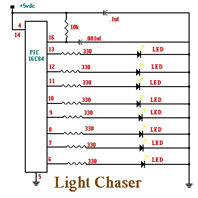
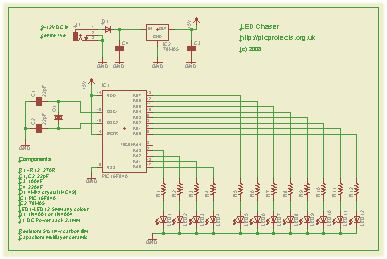
This simple circuit functions as a 12 LED chaser. A single illuminated LED ‘walks’ left and right in a repeating sequence, similar to the effect seen on KITT, the car in the Knight Rider TV series.
Fully commented source code and programmer ready HEX files are provided for the PIC 16F84A and 16F628A at the bottom of this page.
The circuit has been constructed on a PCB but can easily be built on strip-board, or a solderless breadboard.
This project has been put together for anyone starting with their first PIC and the source code is heavily commented with references to the PIC datasheets and the MPASM assembler user guide.
Although the PIC 16F84A is really obsolete and I wouldn’t normally do a project using it, this chip is used extensively throughout education and for many people this will still be their first step into the world of PICs. I’ve also written a version for the PIC16F628A which is a pin compatible replacement for the 16F84A and I would recommend that if you intend to develop your interest in PIC microcontrollers you start using this device rather than the 16F84A.
Please note that the 16F84 and 16F628 without the ‘A’ suffixare not suitable for this project. You must use the 16F84A or 16F628A parts.
The heart of the LED chaser is the PIC microcontroller, IC1. This can be either a PIC16F84A or PIC16F628A as software code is provided for either device. The program that runs on this chip controls the LEDs attached to the output port pins. Resistors R1 thru R12 limit the current through LED1 – LED12 to a safe level that won’t damage the PICs I/O ports or LEDs.
The value of the resistors has been selected to be safe rather provide maximum brightness. If you decide to use high brightness blue, green or white 5mm LEDs you may need to change these from 270ohms to 100ohms. For all other 5mm LEDs the 270ohm resistors will be fine.
Crystal Q1 and capacitors C1 and C2 connect to the oscillator circuit inside the PIC. This generate a stable 4Mhz clock which is used by the PIC to control the timing of the microcontroller core. If you are using the PIC 16F628A you can omit these three components and use the PICs internal RC oscillator. However, you will also need to make a change to the source code before programming the PIC so it knows to use it’s internal oscillator. (see here)
Capacitor C3 is used to decouple the 5 volt power supply rail. If you are building the circuit on a breadboard or stripboard you should ensure it is located close to the PICs Vdd connection (pin 14 ).
The input voltage can be anywhere form 9 to 12 volts but the PIC requires a precisely controlled 5 volt supply. This is provided by IC2, a 78M05 3-terminal 5 volt regulator. Capacitor C4 decouples the input to the regulator. Diode D1 protects the circuit from accidental reverse polarity of the input voltage.
You can buy all the parts needed to build this project from most component suppliers world wide. In the UK you can get everything from Rapid Online and I’ve included a parts list with their part numbers below.
All Rapid parts/descriptions correct at 04-Sept-2008. You should check part# and descriptions are correct when ordering in case I’ve made a mistake transferring them onto this page.
* You can use almost any type of 5mm standard LEDs of any colour with this circuit. If you use blue LEDs you may need to change R1-12 from 270R to 100R.
** use either PIC16F628A or PIC 16F84A
*** If you don’t have a power supply, this one should be suitable.
PIC Programmer
You can also buy the PICkit2 starter kit from Rapid, part # 97-0101
Construction notes:
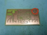
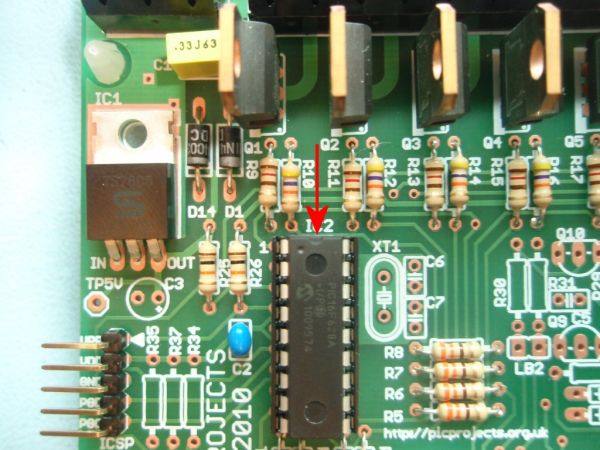
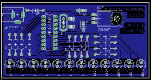
In Fig 1. note how the holes for the DC Power Jack (top right) have been milled into slots to accept the solder tabs on the connector.
The photo shows PCB410A, the artwork and Eagle files on this page are for PCB410B. I’ve made some minor changes to the copper layout to make it easier to solder the LEDs but the component placement remains unchanged.
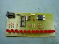
Fig. 2 shows the board with the 4Mhz crystal and capacitors fitted. This board will work with the firmware on this page without modification.
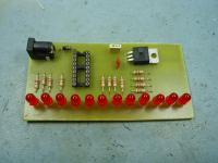
In Fig.3 crystal Q1, and capacitors C1, C2 have been omitted. If you are using a PIC 16F628A you can use the PIC’s internal RC oscillator, in which case you don’t need to fit these components. If you do this you will need to edit the ‘ledchaser16F628A.asm’ file.
You will then need to reassemble the file. If you have installed the Microchip MPLAB IDE software, you can load the asm file and then do a Project – Quickbuild to create the HEX file. Once you’ve done this, program the 16F628A with the new ledchaser16F628A.HEX file.
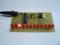
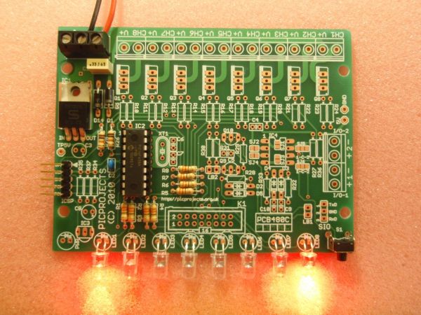
Fig. 4 shows the board running the LED Chaser program.
Power Supply
The board includes a 5 volt regulator and reverse polarity protection diode on board. You will need to use a suitable DC power supply rated between 9 and 12 volts and able to supply at least 200mA.
In the UK you can buy a suitable power supply from Rapid Electronics. The part number for this is included in the component listing above should you not already have something available.
Firmware
You can use either a PIC 16F84A or PIC 16F628A microcontroller with this circuit. Download the files required below.
The HEX files are ready to program straight into the PIC. The asm files are the source code which you can modify or just view to see how it works. If you are going to modify the code I recommend you download and install the Microchip MPLAB IDE which will allow you to edit, modify and program the PIC seamlessly.
If you need a PIC Programmer I strongly recommend the Microchip PICKit 2, this is available from suppliers world wide or direct from Microchip. It’s reasonably cheap to buy and reliable. I have a couple of them and I wouldn’t use anything else now.
As noted elsewhere, the code above will not work with the non ‘A’ suffix parts. While the changes to make it work are minor, I haven’t tested them and therefore I will only support it when used with the 16F84A / 16F628A. Also be aware that the PICkit2 programmer does not support the 16F84 but it does support the 16F84A.
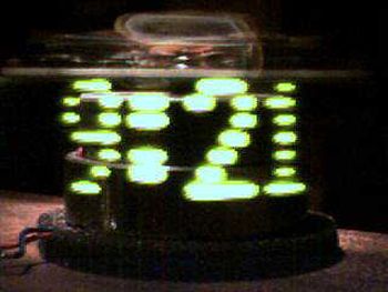
This is the first clock I ever built. I’ve built a few LED signs, but they get boring because I already know the message.
How this clock works: A motor spins the “propeller”, and a small microprocessor keeps track of time and changes the pattern on seven LEDs with exact timing to simulate a 7 by 30 array of LEDs. It is an illusion, but it works nicely.
If you want to build this clock, you will need a few things, including:
Skill with motors and mechanical things.
Prior electronic experience.
A dead VCR or floppy drive or other source of a suitable motor and miscellaneous parts.
A programmer that will program a PIC16C84 or 16F84 microprocessor.
I have provided (almost)everything else: The Next Page with drawings and plans.
Download: mclock.txt A full description how to build it. mclkpart.txt The parts list. mclock8.asm The source code in Microchip MPASM format. mclock8.hex The hex code ready to load into a PIC16C84 or 16F84 chip. mclksch2.gif A large and very readable schematic diagram. mclkmoto.gif A drawing of the modifications to the motor.
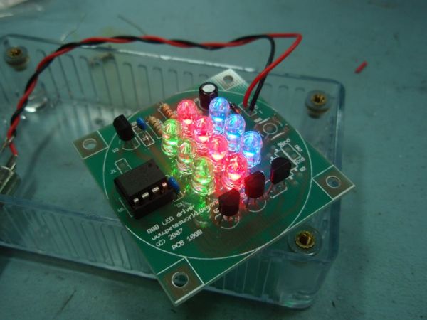
Want to build an RGB LED controller that you can program with your own custom sequences and effects? Then read on.
The RGB LED controller has proved to be very popular project and has been the most frequently downloaded code on the site since it was made available. I’ve been contacted by people who have incorporated this project into all kinds of things including mood lamps, lighting for a sculpture, accent lighting for rooms and an illuminated prize trophy.
For 2006 I completely rewrote the application making it much easier to add, edit and change the sequence data. I also added a sleep function so a battery operated version can be built that doesn’t need a power switch.
For 2008 I’ve released version 3 of the code which now allows you to stop the running sequence at any point so you can ‘freeze’ a colour.
All code runs on the 12F629, 12F675 and the newer 12F683 which, with 2K of program memory has plenty of room for user sequences.
Description
The original RGB PWM driver application that I wrote in 2004 had a few shortcomings. Probably the biggest was that it was not easy to add to or change the sequences. This new version addresses that problem, is more flexible and now includes the ability to put the PIC to ‘sleep’ and ‘wake’ it again using the sequence select switch, eliminating the need for an on/off switch in battery powered applications.
The circuit uses (RGB) Red, Green and Blue high brightness LEDs that are pulse width modulated (PWM) to vary the intensity of each colour LED. This allows effectively any colour to be generated with rapid changing strobe effects, fast and slow colour fades as well as static colours. The data used to set and change the colours is held in an easy to edit file so if you don’t like the sequences provided with it, you can modify the sequence data include file yourself and reprogram with your own sequences.
The code can be assembled for use with the following PICs: 12F629, 12F675, 12F683. Just select the correct processor in the MPLAB IDE before assembling.
How bright are the LEDs
That depends on the specific LEDs you use, the current you drive them with, the angle your view them from etc……..
If you want to know I suggest the best thing to do is buy the LEDs you’re planning to use and connect them up directly to a power supply using a suitable current limiting resistor. If the brightness meets your expectations than go ahead and build this project, but if they don’t they aren’t going to be any brighter in this circuit so you probably need to look at an alternative solution like a large array of LEDs driven with the Power MOSFET Driver project
Since I do not know exactly which LEDs you will use I’ve specified the LED current limiting resistors on the conservative side. You may want to change the value of these resistors to suit the actual LEDs used. Keep the current per channel to under 40mA maximum.
Recently I acquired a 5M length of RGB LED strip using SMD5050 RGB LEDs. It has built in current limit resistors designed for operation from a 12 volt supply. Having thought this would directly attach to the Picprojects MOSFET RGB LED driver project I went ahead and bought one only to discover when it arrived that it wasn’t going to be that easy.
Despite the description and markings on the supplied strip indicating it had a common anode connection it is in fact common cathode. The terminal marked ‘+’ in the photo below is a common ground connection – go figure?
What is required is a high-side driver so the three LED anodes can be controlled by the PWM output from the PIC microcontroller while the common wire connects to ground.
With the requirement defined I decided to put together a quick project to work with the LED strip. The controller on this page is an adaption of the RGB Mood Light 101 project, firmware is the same and can be downloaded from that project page.
You should be aware that not all LED strips use a common ground, I have 1 metre strip that is wired with a common ‘+’ or high-side and works pefectly using the Power MOSFET RGB LED driver kit 106 See my notes on LED strips here
Please note:
This project is NOT available as a kit, or PCB nor can I supply the LED strip.
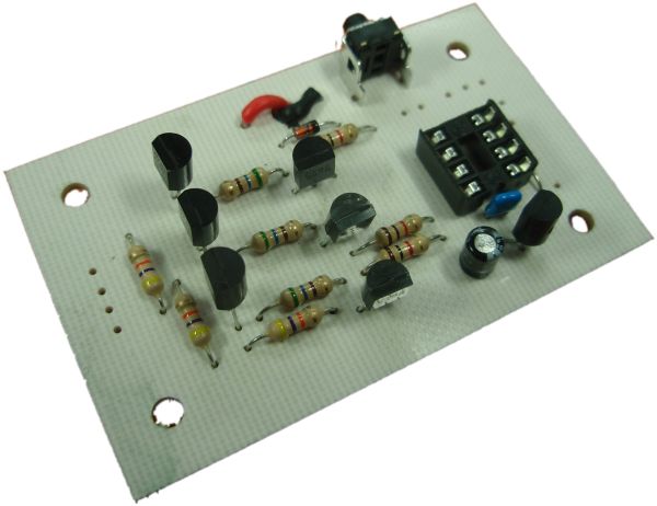
Circuit Description
The circuit is essentialy the same as the RGB101 Mood Light project and uses exactly the same fimware. Where it differs is in the LED output drive stage. Instead of the BC548 transistor (Q1-Q3) driving the LEDs directly they are used to switch a second set of transistors (Q4-Q6). These are STX790A medium power PNP transistors switching the 12 volt or high-side of the power supply.
The current rating of each colour in the strip is around 1.5 amps which needs a medium power transistor to control it. I’ve avoided using a P-channel MOSFET as they are both expensive and less easy to obtain.
The transistor used for the final output is an STX790A rated at a maximum collector current of 3 amps, with a minimum current gain of 100. The LED strips I used require about 1 to 1.5 amps per colour. Base current for Q4-Q6 is derived from the collector current of the BC548 transistors (Q1-Q3) via R1 – R3. Resistors R1-R3 provide around 20mA of base current to the STX790A. I’ve used 560R 0.25 watt carbon film resistors here, they are operating right on their power dissipation limit for a 0.25 watt resistor. Since the transistors are driven with a PWM signal average power dissipation is lower so not an issue.
If you decide to use an alternative transistor type for Q4-Q6 and need to increase the base current you’ll need to use a 1/2 watt resistor or go for a metal film 0.4 watt or 0.6 watt which are the same physical size as a 0.25 watt carbon film.
For Q1-Q3 any small signal NPN transistor will work. BC546, BC547 or BC549 are also suitable and have the same pinout as the BC548.
If you need more than 2 amps per LED channel you will need to do some redesign of the final transistor output section since the circuit is not designed to handle more than 2 amps on each channel.
The rest of the circuit is straight forward.
The 12 volt input to the board is fed through D1 to a 78L05 5-volt regulator (IC2). D1 provides reverse polarity protection to the regulator though it should be noted this does not protect the LEDs and final driver transistors since due to the high current requirements of the LED strip it is not practical to use a diode here.
Capacitor C1 provides decoupling of the 5 volt supply. Capacitor C2 provides filtering on the input side of the regulator. C1 should be as close to the PICs Vdd/Vss power input (pins 1/8) as practical. The 78L05 and C2 should also be reasonably close to each other and the PIC. R7 provides a pull-up for the PICs MCLR reset input.
S1 is the mode control switch. JP3 just provides a pair of 0.1″ spaced pads for connecting a remote switch if the board is built into a housing.
JP2 is the LED output connector. Take note of the connections on this. The ground, red, green and blue connections have been placed to match the LED strip I was using. You should verify the connections to the specific LED strip you use to ensure they are the same. (see notes on LED strips here)
Also remember the board switches the high or 12 volt side with the ground connection being common to all three LED colours. If you have a common anode strip you will need the Power MOSFET project.
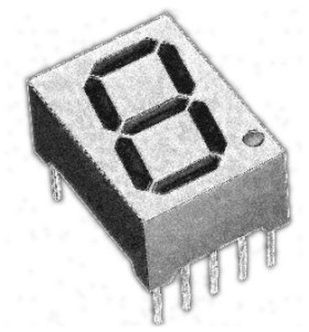
This is a building block project I developed to try out a few ideas. It decodes a 4-bit binary word to outputs that will drive a 7-segment LED display. Functionality is similar to the 7447 BCD-to-seven-segment decoder/driver IC however, because it’s implemented using a microcontroller, the segment control data can be customised to display any set of 16 characters you wish to create. It also has an ‘invert’ control input that allows it to drive either common anode (active low) or common cathode (active high) LED modules.
Binary or BCD to 7-segment decoder
4-bit binary input to 7-segment decode, 0-9, A-F
Lamp test input
Zero blanking
output invert, allows use of common anode or common cathode displays
The idea behind this project is that the PIC can be used as a decoder for 7-segment LED displays and therefore it will be built into some other application. The schematic is provided for evaluation only.
The PIC use an internal clock source so no external timing components are required, you will need to fit a decoupling capacitor across the Vdd/Vss supply close to the PIC; 100nF ceramic will do the job..
Inputs require an external pull-up resistor unless actively driven by an external source. All unused inputs should be tied to Vdd via a 4K7 resistors.
Because the decoder is implemented in software running on the PIC, input to output propagation delays are 15uS. Input data on A0-A3 should be held for 15uS after en/latch input goes high to ensure input is latched.
Outputs on the PIC16F627A / 628A are rated at 25mA with a maximum of 200mA for all I/O pins. This means it can drive a 7-segment LED display directly (via current limit resistors).
Customizing Segment Data
The segment data used to drive the outputs is held in the EEPROM of the PIC making it easy to edit without having to reassemble the source code.
The data is held at addresses 00 to 0F in the format shown below
This neat little circuit provides 8 LEDs directly driven from the PIC along with a single mode control switch. The firmware elsewhere on this page drives the LEDs with a 5 bit PWM signal providing each of the 8 LED channels with four levels of intensity; off, dim, mid, bright. A number of sequences are programmed into the firmware to provide some interesting visual effects and chase sequences, including the classic effect seen on the car in the Knight Rider TV series.
The software has sequential, random and manual sequence run modes and manual advance to the next sequence in any mode. The selected sequence and mode are also saved to non-volatile memory so it will always restart in the selected mode.
The design is deliberately simple with each LED being directly driven from a PIC I/O pin. This and the inclusion of an in-circuit programming header (ICSP) make the circuit ideal for teaching/learning introductory PIC assembly language programming.
You can use it with different sized LEDs and mixed colours, as well as fewer than 8 LEDs. As well as using it as a LED chaser it is great for adding effects to toys and models. See FAQ
However, if you just want a cool LED chaser without having to write any code, a ready written LED chaser program including 34 chase effects with source code and programmer ready HEX files is provided at the bottom of this page.
The circuit has been constructed on a PCB but can easily be built on strip-board or a solderless breadboard.
The heart of the LED chaser is the PIC 16F628A microcontroller, IC2. The program that runs on this chip controls the LEDs attached to the output port pins. Resistors R1 thru R8 limit the current through LED1 – LED8 to a safe level that won’t damage the PICs I/O ports or LEDs. The LEDs can either be mounted on the PCB or via header plug K1 and a ribbon cable which permits the LEDs to be mounted in a different arrangement, location etc. If the LEDs are connected via the K1 header, don’t install LEDs on the PCB, it’s either or but not both.
Resistor R25 provides a pull-up for the input connected to switch S1. R26 pulls up the PIC’s MCLR reset signal during normal operation while allowing the input to be raised to 12.5 volts during in-circuit programming. The ICSP header provides connection for an ICSP programmer such as a PICkit2 making it easy to reprogram the PIC without removing it from the PCB.
Capacitor C2 is used to decouple the 5 volt power supply to the PIC. If you’re building the circuit on a breadboard or stripboard you should ensure it is located close to the PICs Vdd connection (pin 14 ).
Power is supplied to the circuit through the 3-way terminal block and must be smooth DC between 9 and 18 volts. The PIC requires a precisely controlled 5 volt supply and this is provided by IC1, a 7805 3-terminal, 5 volt regulator. Typical current drawn by the circuit with all LEDs on is only around 100mA so the voltage regulator doesn’t require any additional heatsink. Capacitors C1 stabilize the regulator. Diode D1 protects the circuit from accidental reverse polarity of the input voltage. Diode D14 protects the regulator and is only really needed if you will be using the ICSP feature (doesn’t hurt to fit it anyway)
The latest high brightness LEDs are very bright even with 330R current limiting resistors. However, if you do need to change these resistors for some reason take into account the maximum current that the PIC can source from an I/O port pin is 25mA, and also be aware that the output voltage will drop as you increase the load. Ideally keep the current per output under 15mA
If you install LEDs that require a lower value series resistor you may find you are unable to program the PIC in-circuit via the ICSP header. This is because the I/O port pins on the PIC that are used for In-Circuit Serial Programming are shared with the LEDs. The programmer may be unable to drive these lines when lower value resistor are used. With the 330R resistors and PICKit2 programmer, In-Circuit programming should work without problems.
The ICSP header allows programming of the PIC while installed in the circuit. It is only required if you intend to connect a programmer to modify the sequences or code. It is not supplied with the kit but is available as an option.
This neat little circuit provides 8 LEDs directly driven from the PIC along with a single mode control switch. The firmware elsewhere on this page drives the LEDs with a 5 bit PWM signal providing each of the 8 LED channels with four levels of intensity; off, dim, mid, bright. A number of sequences are programmed into the firmware to provide some interesting visual effects and chase sequences, including the classic effect seen on the car in the Knight Rider TV series.
The software has sequential, random and manual sequence run modes and manual advance to the next sequence in any mode. The selected sequence and mode are also saved to non-volatile memory so it will always restart in the selected mode.
The design is kept simple with each channel being directly driven from a PIC I/O pin. On board LEDs allow operation to be monitored while the power MOSFETs enable the board to control LED arrays and modules at currents up to 2 amps.
You can use it with different sized LEDs and mixed colours, as well as fewer than 8 LEDs. As well as using it as a LED chaser it is great for adding effects to toys and models. See FAQ
However, if you just want a cool LED chaser without having to write any code, a ready written LED chaser program including 34 chase effects with source code and programmer ready HEX files is provided at the bottom of this page.
Circuit Description
The heart of the LED chaser is the PIC 16F628A microcontroller, IC2. The program that runs on this chip controls the LEDs / MOSFET drivers attached to the output port pins. Resistors R1 thru R8 limit the current through LED1 – LED8 to a safe level that won’t damage the PICs I/O ports or LEDs. These LEDs are provided to monitor the main channel outputs, they can be omitted them if this feature isn’t needed.
Resistor R25 provides a pull-up for the input connected to switch S1. R26 pulls up the PIC’s MCLR reset signal during normal operation while allowing the input to be raised to 12.5 volts during in-circuit programming. The ICSP header provides connection for an ICSP programmer such as a PICkit2 making it easy to reprogram the PIC without removing it from the PCB.
Power is supplied to the circuit through the 3-way terminal block and must be smooth DC between 9 and 18 volts. The PIC requires a precisely controlled 5 volt supply and this is provided by IC1, a 7805 3-terminal, 5 volt regulator. Typical current drawn by the circuit with all LEDs on is only around 100mA so the voltage regulator doesn’t require any additional heatsink. Capacitor C1 stabilizes the regulator. Capacitors C2 / C4 are used to decouple the 5 volt power supply to the board. Diode D1 protects the circuit from accidental reverse polarity of the input voltage. Diode D14 protects the regulator and is only really needed if you will be using the ICSP feature (doesn’t hurt to fit it anyway)
The power output stage comprises eight STP36NF06 N-Channel MOSFETs. These are logic level devices with a low (logic level) gate threshold making them suitable for driving from a PIC output. The 120R gate resistors limit the current during switching, the 47K gate pull-down resistors prevent the MOSFETs from turning on during power up and also from ESD (electro-static discharge).
Although rated at maximum of 30amps and 60 volts source/drain voltage, since the MOSFETs are being used without any heatsink do not exceed 2 amps per channel. In addition to this the connectors and PCB track sizing also limit the maximum current per channel to 2 amps. DO NOT EXCEED 2 AMPS per CHANNEL
The 3-way terminal block supplied with the kit is rated for 20 amps per terminal. There are two terminals connected to V- (Ground). When operating the board at maximum channel output currents it is good practice to wire both inputs to ground.
Each channel can handle 3 amps however the combined channel current for the board should not exceed 16 amps in total (2 amps per channel when all channels are active simultaneously)
The ICSP header allows programming of the PIC while installed in the circuit. It is only required if you intend to connect a programmer to modify the sequences or code. It is not supplied with the kit but is available as an option.
The board itself requires around 100mA to operate, however, the power supply used will need to be specified to handle the total power required for whatever LED modules / arrays are connected to the MOSFET output channels.
This neat little circuit provides 8 LEDs directly driven from the PIC along with a single mode control switch. The firmware elsewhere on this page drives the LEDs with a 5 bit PWM signal providing each of the 8 LED channels with four levels of intensity; off, dim, mid, bright. A number of sequences are programmed into the firmware to provide some interesting visual effects and chase sequences, including the classic effect seen on the car in the Knight Rider TV series.
The software has sequential, random and manual sequence run modes and manual advance to the next sequence in any mode. The selected sequence and mode are also saved to non-volatile memory so it will always restart in the selected mode.
The design is deliberately simple with each LED being directly driven from a PIC I/O pin. This and the inclusion of an in-circuit programming header (ICSP) make the circuit ideal for teaching/learning introductory PIC assembly language programming.
You can use it with different sized LEDs and mixed colours, as well as fewer than 8 LEDs. As well as using it as a LED chaser it is great for adding effects to toys and models. See FAQ
However, if you just want a cool LED chaser without having to write any code, a ready written LED chaser program including 34 chase effects with source code and programmer ready HEX files is provided at the bottom of this page.
The circuit has been constructed on a PCB but can easily be built on strip-board or a solderless breadboard.
Circuit Description
The heart of the LED chaser is the PIC 16F628A microcontroller, IC2. The program that runs on this chip controls the LEDs attached to the output port pins. Resistors R1 thru R8 limit the current through LED1 – LED8 to a safe level that won’t damage the PICs I/O ports or LEDs. Resistor R9 provides a pull-up for the input connected to switch S1. R10 pulls up the PIC’s MCLR reset signal during normal operation while allowing the input to be raised to 12.5 volts during in-circuit programming. JP1 provides connection for an ICSP programmer such as a PICkit2 making it easy to reprogram the PIC without removing it from the PCB.
Capacitor C1 is used to decouple the 5 volt power supply to the PIC. If you’re building the circuit on a breadboard or stripboard you should ensure it is located close to the PICs Vdd connection (pin 14 ).
Power is supplied to the circuit via J1 and must be smooth DC between 9 and 14 volts. The PIC requires a precisely controlled 5 volt supply and this is provided by IC1, a 7805 3-terminal, 5 volt regulator. Typical current drawn by the circuit with all LEDs on is only around 100mA so the voltage regulator doesn’t require any additional heatsink. Capacitors C2 and C3 stabilize the regulator. Diode D1 protects the circuit from accidental reverse polarity of the input voltage.
Notes:
Capacitors C2/C3 stabilize the voltage regulator and may be omitted for most applications, however the schematic shows them and the PCB layout makes provision for them. If you’re unsure whether you will need them then it’s best to install them.
The latest high brightness LEDs are very bright even with 270R current limiting resistors. However, if you do need to change these resistors for some reason take into account the maximum current that the PIC can source from an I/O port pin is 25mA, and also be aware that the output voltage will drop as you increase the load.
If you install LEDs that require a lower value series resistor you may find you are unable to program the PIC in-circuit via the ICSP header. This is because the I/O port pins on the PIC that are used for In-Circuit Serial Programming are shared with the LEDs. The programmer may be unable to drive these lines when lower value resistor are used. With the 270R resistors and PICKit2 programmer, In-Circuit programming should work without problems.
JP1 is an ICSP header to allow programming of the PIC while installed in the circuit. It is only required if you intend to connect a programmer to modify the sequences or code. It is not supplied with the kit.Pin 2 of this header connects to the circuit’s 5 volt supply via the link LK1. Since the circuit provides an onboard 5 volt regulator, the circuit should be powered from this and the link left open. Pin 1 of the ICSP header JP1 is nearest the LEDs
If you have an external 5V supply, you can omit D1, C2, C3 and IC1. You will need to install wire links in place of D1, and between pins 1 and 3 (in-out) of IC1. The circuit will now work from the external 5V supply. Be sure to connect it up correctly because without D1 in place there is no reverse polarity protection.
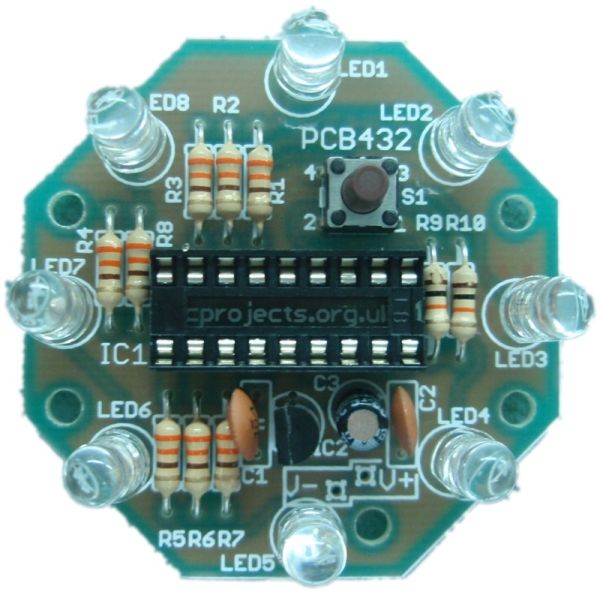
This page is has been written to support construction of the UFO LED Chaser Kit #432K.
This neat little circuit provides 8 LEDs directly driven from the PIC along with a single mode control switch. The firmware elsewhere on this page drives the LEDs with a 5 bit PWM signal providing each of the 8 LED channels with four levels of intensity; off, dim, mid, bright. A number of sequences are programmed into the firmware to provide some interesting visual effects and chase sequences.
The software has sequential, random and manual sequence run modes and manual advance to the next sequence in any mode. The selected sequence and mode are also saved to non-volatile memory so it will always restart in the selected mode. The firmware is the same as that used in the linear PWM LED chaser project.
The design is deliberately simple with each LED being directly driven from a PIC I/O pin. You can use it with different sized LEDs and mixed colours, as well as fewer than 8 LEDs. As well as using it as a LED chaser it is great for adding effects to toys and models. See FAQ
The firmware pre-programmed into the PIC16F628A supplied with the kit includes over 34 chase effects and sequences. If you’re interested in PIC micros and programming and want to modify the sequences or create new ones, the source code and programmer ready HEX files is provided at the bottom of this page.
The heart of the LED chaser is the PIC 16F628A microcontroller, IC2. The program that runs on this chip controls the LEDs attached to the output port pins. Resistors R1 thru R8 limit the current through LED1 – LED8 to a safe level that won’t damage the PICs I/O ports or LEDs. Resistor R9 provides a pull-up for the input connected to switch S1. R10 holds the PICs MCLR reset signal high.
Capacitor C1 is used to decouple the 5 volt power supply to the PIC. If you’re building the circuit on a breadboard or stripboard you should ensure it is located close to the PICs Vdd connection (pin 14 ).
Power is supplied to the circuit via the V+/V- solder points. The voltage regulator used is a LM2931-5.0, low-drop-out regulator and will maintain regulation with an input voltage down to 6 volts. Input voltage for the LED chaser should be between 6 volts and 14 volts to ensure power dissipation remains within limits. The LM2931-5.0 regulator is designed for battery powered and automotive applications and includes internal current limiting, thermal shutdown, as well as reverse battery connection without damage to itself or the circuit behind it. Capacitor C3 is important and must be fitted to prevent instability of the regulator output
Typical current drawn by the circuit with all LEDs on is only around 80mA; with all LEDs off it’s under 1mA.
Notes:
The latest high brightness LEDs are very bright even with 330R current limiting resistors. However, if you do need to change these resistors for some reason take into account the absolute maximum current that the on-board voltage regulator can deliver is 100mA.
If you do change the current limit resistors to suit different LEDs you should aim for the LED current for each output to be no more than 10mA ( 80mA total for all 8 outputs)
The 330R resistors are specified so that with a LED forward voltage of 1.7 volts and the circuit operating at 5 volts the LED current will be 10mA. LEDs with a higher forward voltage will draw less current. Most LEDs have a forward voltage greater than 1.7 volts so the circuit will work with the majority of LEDs and stay well within the design limits of the circuit.
The LED forward voltage parameter for a specific LED will normally be found in the manufacturers data sheet.
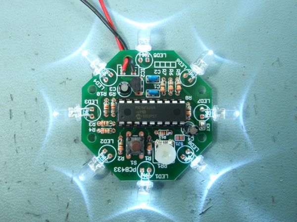
This is an updated version of the UFO LED Chaser project, revised to use the PWM LED Chaser code version 3.0.0 with support for variable chase speed. The basic LED chaser ‘engine’ firmware is the same as that used with the 481/483 LED chaser projects also on this site. The only difference is the sequence data used to create the programmer ready .HEX file. This has been modified to include chase effects that suit the circular arrangement of LEDs.
Unlike many simple LED chaser projects the design presented here provides 8 LEDs directly driven from the PIC along with a single mode control switch and speed adjust control. The firmware elsewhere on this page drives the LEDs with a 5 bit PWM signal providing each of the 8 LED channels with four levels of intensity; off, dim, mid and bright. A number of sequences are programmed into the firmware to provide some interesting visual effects and chase sequences.
The software has sequential, random and manual sequence run modes and manual advance to the next sequence in any mode. The selected sequence and mode are also saved to non-volatile memory so it will always restart in the selected mode.
The design is deliberately simple with each LED being directly driven from a PIC I/O pin. You can use it with different sized LEDs and mixed colours. While it works well as a simple LED chaser, thinking outside the box it can be used to add effects to toys and models and even accessorize fancy dress costumes. See FAQ
A solder pad jumper on the PCB selects between fixed speed chaser using internal timing or variable chase speed adjustable using the on-board variable resistor. The adjustable chase speed option makes it ideal for use in a wide range of applications. The kit 433K includes all parts needed to build the variable speed chaser.
The firmware pre-programmed into the PIC16F628A supplied with the kit includes over 34 chase effects and sequences. If you’re interested in PIC micros and programming and want to modify the sequences or create new ones, the source code and programmer ready HEX file is provided at the bottom of this page.
The heart of the LED chaser is the PIC 16F628A microcontroller, IC1. The program that runs on this chip controls the LEDs attached to the output port pins. Resistors R1 thru R8 limit the current through LED1 – LED8 to a safe level that won’t damage the PICs I/O ports or LEDs. Resistor R9 provides a pull-up for the input connected to switch S1. R10 holds the PICs MCLR reset signal high.
The variable resistor PR1 along with C4 are used to create a software oscillator. C4 is charged and discharged via PR1 from port B0 output. The input on Port A7 is monitored by the firmware, when the input goes high port B0 is driven low to discharge C4. When Port A7 goes low, port B0 is driven high to charge C4. An important requirement is the use of a Schmitt trigger input buffer on Port A7 input pin which provides the necessary hysteresis to make the software oscillator work. This oscillator is then used to provide the clock for the chaser timing and since the speed is controlled by the rate C4 charges through PR1 the chaser speed can be controlled by adjusting PR1. A 1K0 resistor, R11 is placed in series with PR1 to set the maximum chase speed when PR1 is adjusted to minimum resistance.
Capacitor C1 is used to decouple the 5 volt power supply to the PIC. If you’re building the circuit on a breadboard or stripboard you should ensure it is located close to the PICs Vdd connection (pin 14 ).
Power is supplied to the circuit via the +/- solder points. The voltage regulator, IC2 is a LM2931-5.0, low-drop-out regulator and will maintain regulation with an input voltage down to 5.8 volts. Input voltage for the LED chaser should be between 6 volts and 14 volts to ensure power dissipation remains within limits. The LM2931-5.0 regulator is designed for battery powered and automotive applications and includes internal current limiting, thermal shutdown, as well as reverse battery connection without damage to itself or the circuit behind it. Capacitor C3 is important and must be fitted to prevent instability of the regulator output
Typical current drawn by the circuit with all LEDs on is only around 80mA; with all LEDs off it is under 5mA.
Notes:
The latest high brightness LEDs are very bright even with 330R current limiting resistors. However, if you do need to change these resistors for some reason take into account the maximum current that the on-board voltage regulator can deliver is 100mA.
EXT solder bridge jumper.
When left open the chaser runs at a fixed speed using the internal sequence timing data.
When closed (bridged with solder on the PCB) the chaser uses the software controlled oscillator for timing, the frequency is adjusted using PR1 which in turn controls the chase speed.
If you leave the ‘EXT’ jumper open, you can omit PR1, R11 and C4. The circuit and firmware will operate correctly using the internal timing data.
The jumpers marked ‘SJ1‘ and ‘MODE‘ are not currently used. Do not bridge them with solder.
This post provides the code to make an LED blink using PIC16F84A microcontroller. This code is written in C language using MPLAB with HI-TECH C compiler. This code is intended to be the first step in learning how to use PIC16F84A microcontroller in your projects. You can download this code from the ‘Downloads‘ section at the bottom of this page.
Following figure shows the minimum circuit required to make an LED blink with PIC16F84A.
In this figure, first thing to note is that there is a crystal of 20MHz used with PIC16F84A[1]. You can use any crystal from 0 to 20MHz with PIC16F84A. MCLR master reset pin is pulled high to keep PIC16F84A out of reset. RA0 pin is being toggled in the code.
Code
The code for making LED blink using PIC16F84A is shown below.
Whenever you are writing code for PIC microcontrollers, then you have to include “htc.h” file in the code. After including “htc.h” file, configuration bits are being set in the code shown above. To understand the details of how these configuration bits are being programmed, you can read this post.
Downloads
LED blinking code using PIC16F84A was compiled in MPLAB v8.85 with HI-TECH C v9.83 compiler and simulation was made in Proteus v7.10. To download code and Proteus simulation click here.
This post provides the code to make an LED blink using PIC12F675 microcontroller. This code is written in C language using MPLAB with HI-TECH C compiler.
This code is intended to be the first step in learning how to use PIC12F675 microcontroller in your projects. You can download this code from the ‘Downloads‘ section at the bottom of this page.
Following figure shows the minimum circuit required to make an LED blink with PIC12F675.
In this figure, first thing to note is that no crystal oscillator is used with PIC12F675, because internal oscillator of 4MHz frequency is being used as the clock source here. GP3 is usually the master reset pin for PIC12F675 microcontroller. But to increase total number of pins available for other purposes, here I am not using GP3 pin as reset pin. So, to make this PIC12F675 microcontroller work, you only need to provide power on the pin 1 and pin 8 of this microcontroller.
Code
The code for making LED blink using PIC12F675 is shown below.
Whenever you are writing code for PIC microcontrollers, then you have to include “htc.h” file in the code. After including “htc.h” file, configuration bits are being set in the code shown above. To understand the details of how these configuration bits are being programmed, you can read this post.
Downloads
LED blinking code using PIC12F675 was compiled in MPLAB v8.85 with HI-TECH C v9.83 compiler and simulation was made in Proteus v7.10. To download code and Proteus simulation click here.
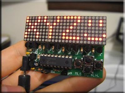
Here you can find out how to drive an led matrix with 64 LEDs (8 rows by 8 columns – 8×8 display) or less e.g. 35 LEDs (7 rows by 5 columns – 5×7 dot matrix).
It uses persistence of vision to let you drive the 64 led matrix with only 10 microcontroller outputs!
Normally you would need 64 outputs for 64 LEDs but by using multiplexing and a helper chip you can get away with 10.
LED Display multiplexing simply means turning on one led for a short period of time and doing this repeatedly for each LED.
If you do this fast enough then your eye will not notice any flicker.
Note: The unit used in this project is simply an array of 64 LEDs.
The LEDs are no different to any other LEDs but it saves a huge amount of soldering as all the wiring has been done for you.
…Or you could wire it up yourself if you can’t get hold of the module.
If you wire it yourself you still only need 10 control wires (just wire you leds the same as shown in the module diagram).
A dot matrix led display is simply a grid of LEDs arranged for use by multiplexing.
Specification
dot matrix led display driver
Red 8×8 LEDs
Multiplexing
If you tried to drive 64 individual LEDs you would need 64 individual output pins (each led connected to a output pin on one side and ground on the other).
Obviously that is a tall order so the way round it is to use persistence of vision which is a way of describing how your eye works.
Your eye reacts slowly to changes in light intensity so that if a light is turned on and off quickly enough then it does not notice that the light is off. Basically your eye remembers a light pulse for a short time.
The approximate time is 20ms so if the light is turned on at a frequency >50Hz (1/20ms) then your eye will not notice any flicker at all.
Multiplexing uses this fact to reduce the number of pins needed to drive an LED display. You can do this by splitting the 64 led display into 8 rows and 8 columns which lets you drive it using 8 row outputs and 8 column outputs. In fact the 8×8 led matrix block used here has all the leds arranged in this way already.
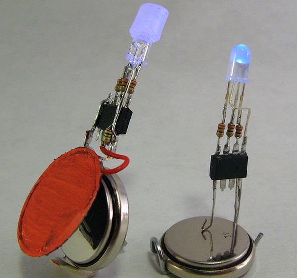
A very popular type of LED that has finally come about is the tri-color, RGB LED. The RGB stands for: red, green and blue since the LED is capable of displaying all three colors, independently. This means that an RGB LED can display any color of the rainbow. This is a powerful capability, but it also requires more control.
In this article, we shall look at how to build an RGB LED controller so that we have accurate and independant control over all three colors at any instant. The method of Fading LEDs via PWM will be leveraged for this design, since our goal here is quite similar, but with more control paths.
Purpose & Overview of this project
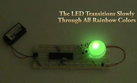
The purpose of this project is to build an RGB LED controller that can display all the colors of the rainbow is a slow, but methodical motion. A microcontroller should be used with 3 digital outputs. An interrupt timer routine will be used to keep track of elapsed time, along with counters to know what duty cycle the PWM control should be outputting.
The PIC 18F452 will be used as the microcontroller of this project with a 40 MHz crystal clock. Running this fast will allow the microcontroller a greater resolution of control for the PWM’s duty cycle. A common-cathode high intensity RGB LED will be used with 3 2N2222 general purpose transistors to control switching when the R/G/B portions of the LED should be connected to power or ground.
Parts List Details
The parts used in this project are virtually the same as with the Fading LEDs via PWM article, we’ll use a few more 2n2222 tranistors, resistors and an RGB LED instead of a standard 1 color LED.
PIC 18F452
This microcontroller built by microchip will serve as the intelligent device for our system, controlling the RGB LED at our will. It will run at a 40 MHz crystal clock speed, which is the maximum for the PIC18F452.
7805 +5 Voltage Regulator
This +5v regulator will be used create the power supply source for all of the electronics used in this circuit. Since the circuit is very small the actual load placed on this regulator will be small, maybe 100 miliamp.
PICkit 2
The PICkit 2 is a programmer for the Microchip PIC microcontroller and it has a legacy for being one of the best, even with the 3rd version already available. You will need some programmer to get your programs onto the PIC and this is the one that I suggest.
2N2222 General Purpose Transistor
This 2N2222 transistor will be used to control the LED state between on and off. The transistor will be connected directly to the microcontroller which will send a signal telling the transistor what state it should be in: on or off.
RGB LED
This is the common-cathode RGB LED. It has 4 wires coming out of it. The longest wire is the ground pin. The other 3 wires connect to the anode of the Red, Green and Blue LEDs. You can test each portion of the LED by connected a 100Ω resistor a power source (9v battery) and the ground pin to ground.
Jumper Wires & Breadboard
I prefer to use a breadboard with the projects in my articles because they offer maximum flexibilty with circuit design with minimal downtown between changes. In addition to the breadboard you will need jumper wire to get everything connected together.
Schematic Overview
The schematic for this tutorial was kept as simple as possible so that the focus could remain on how the touch screen works and how we interface to it. You can see the completed schematic for this project below. The main parts in the schematic are the RGB LED, 18F452 and LM7805.
Schematic Specifics
Power Regulator
The power regulation circuit is a LM7805 +5v regulator that will convert the +9v from the battery to a steady +5v output to the PIC.
PIC Microcontroller Circuit
The microcontroller circuit consists of the PIC 18F452, it’s 40 MHz crystal clock and the 10k resistor connected to pin 1, MCLR. Along with power and ground connections, these are the basic connections necessary to run the program loaded on the PIC.
In the post ‘LED 7-Segment Multiplexing‘, I have explained about the concept and benefits of multiplexing. Multiplexing implementation is very similar to driving Led Dot Matrix. I use Timer0 interrupt for switching through each digit. Timer0 or TMR0 is an 8-bit timer which overflows every 256 (0xFF) counts. It’s known that the refresh rate above 50Hz would be enough for human’s eyes to see the display without recognizing the flickering. If I set TMR0 with 1:8 Prescaler, the multiplexing frequency will be
4MHz(internal OSC.)/4(working OSC)/8(prescaler)/256(max counts of TMR0)/6(number of digits) = 81.3 Hz which is good for a display.
Just an example, I have implemented (in Proteus) a 999999-second counter by using 6 Digits LED 7-Segment Multiplexing technique. There are 2 main components in the project, PIC16F627A or PIC16F628 and 6 x LED7-segment display. The schematic shows below. The crystal is 32.768KHz as usual. There is a 10KOhm pull up resistor at RA4 pin as this pin is an open-drain pin as I described in “Open-Drain RA4 pin on PIC Microcontroller“.
The source code in MikroC is listed below: (.hex is also available, please feel free to contact me)
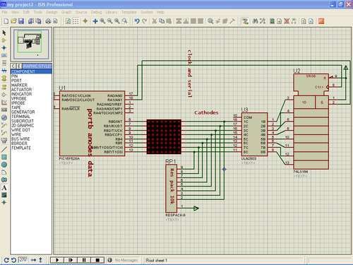
This is aproject to move words on led matrix display
we use
1-pic16f628a as microcontroller :cheap,program memory 2k,has internal oscillatror,two ports A,B and alot of things.
2-led matrix 8*8 rows common anode and columns common cathode
3-shift register i use 74ls164 it is simple than 74595 his job is scanning columns activate one at atime
4-uln 2803
every time maximum of eight led work so current=8*(15ma for every led=120ma
shift register can’t sink this much current so we use uln .it can sink current up to 500ma
5-eight resistors 120ohm,pack resistors 10k
The Complete Circuit diagram is Shown
Step 1: Led matrix construction
ledmatrix is shown in pictures
to light aspecfic led we apply logic high(1) to anode and logic zero to cathode
so we make anode as data source and cathode as scanning (activate cathode of aspecfic column) so we connect anodes(rows) to portb and cathodes to uln and shift register
we discuss this later
Step 2: Shift register 74ls164
We must shift register very well to make this project.In general shift register is used to extend microcontroller terminals he take 3 terminals from any port and give us 8 terminals.
This shift register is serial input parrel output takes data serially and output it by clock
shift register in simple words consist of :
1-two serial input A,B pin number(1-2)
two serial input is anded so we connect one of them to vcc (1) and other is serial input controlled by pic16f628a.
2-clock pin8
3-eight outputs QA to QH
4-clear pin 9 connect to vcc when connect to ground it clear output pins
5-vcc and ground pin 7 – 14
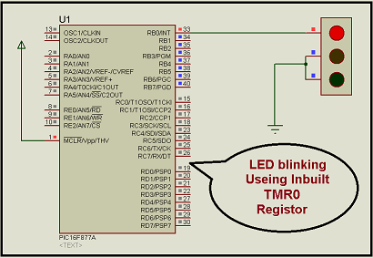
Here I discuss very good knowledge based project LED blinking using timer0 of pic16f877 microcontroller. You can see in my Earlier project “Simple Project on LED blinking by PIC 16 Microcontroller” where I have used delay program for LED blinking. For LED blinking we have to call inbuilt/external delay program. Now think without calling delay program how LED blinking is possible?
It is possible and possible by using timer 0 of pic16f877 microcontroller. As we know pic16f877 microcontroller has three inbuilt timers. 1. Timer 0 2. Timer 1 3. Timer 2. For more knowledge on timer in pic16f877 please go through my old post “Timer Modules in pic16f877 microcontroller”.
Project Description
In this project, it is very easily discuss that how easily a LED is blinking using inbuilt timer of pic16f877 microcontroller with exact 1 sec time interval. Now think about the Timer0 register, which is TMR0 and how it work. We know TMR0 is 8-bit register so it takes time to count from 00h to FFh is 255×0.2µs=51µs (If we use 20 MHz crystal oscillator to run the microcontroller). In TMR0 when 255 count complete the overflow done and overflow flag is set. Now calculate how many overflow would we need, if we want to have an exact 1 second time delay? It would be over 19500 overflows. For 1ms delay would require about 20 overflows because we see for 1 overflow 51µs is needed. Now concentrate on prescaler value and how it affects counting of TMR0. Prescaler value of 1:4 would take 4 instruction cycles to increment TMR0 by 1. On the other hand, prescaler value of 1:256 requires 256 instruction cycles for the increment. With prescaler value of 1:256, one overflow would take 255x256x0.2µs=13056µs. Therefore, with 1:256, it would take only 76 overflows to have an exact 1 second timing.
See the simple simulation circuit diagram of project “LED blinking using timer0 of pic16f877 microcontroller “
Now in c programming we have to concentrate on two spacial register operation_reg and INTCON. And we have to set proper bit pattern for both of this register as per our project need. For this project i set operation_reg = 87 H and INTCON= 00H. why i set operation_reg = 87 H and INTCON= 00H? For that please go through my post “Timer Modules in pic16f877 microcontroller”.
Now we can concentrate on Bit 2 position that is T0IF, of INTCON register because this bit is responsible for overflow occur in side TMR0. If TMR0 overflow occur it will set.
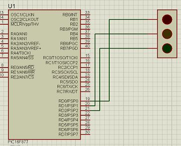
Today I will show you how easily you can build your first project on blinking LED by using PIC 16 microcontroller. In my previous post Step by step Project guide on PIC Microcontroller I was mansion that for start-up we need
1 Proteus 7 Professional (where we Make your hardware arrangement our project and simulate it to see the result)
2 Mikcro C. (here we write the Embedded C Program and build the hex file of that)
Start with Proteus
Click on new file it will open blank work pace.
Now to make our project we need and add PIC 16, Crystal, Traffic light.
Now place this on workplace and connect them
Now question is how to do that? For that see the video which will make you understand easily.
Now last and main question is how to write your program?
See in PIC16 four ports are available Port A, Port B, Port C, Port D. Now you have to know the procedure to define those ports as an input or output. For defining ports you can use TRIS command. Let suppose you have to define port D then your command will be TRISD.
Now how to define port D as a input or output for that the format will be
TRISD = 1 (input)
TRISD = 0 (output)
Now see the hardware connection, three LEDs are connected in Port D bit 0, bit 1 and bit 2 positions. So now for glow the
Upper led we have to send 00000001 = 1
Middle LED we need to send 00000010 = 2
Lower LED we need to send 00000100 = 4
So for our Simple Project on LED blinking by PIC 16 Microcontroller we have to send the number Port D =1, Port D= 2 and Port D = 4 with some delay .
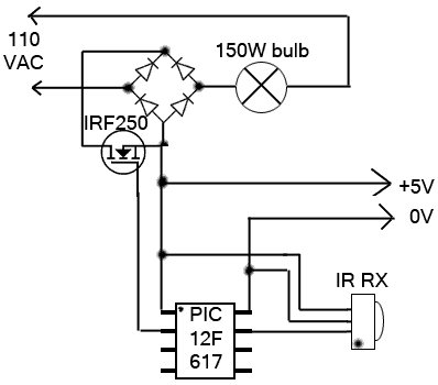
The lamp in my bedroom is a very cheap lamp from Wal-Mart. It stands in one corner of my room, opposite of the door. This is where the problem is: If it is dark, I have to walk across the room, not trip on anything, find the small knob to twist to turn on the lamp, walk back towards whatever I need to do in the room. That is a whole lot of unnecessary walking.
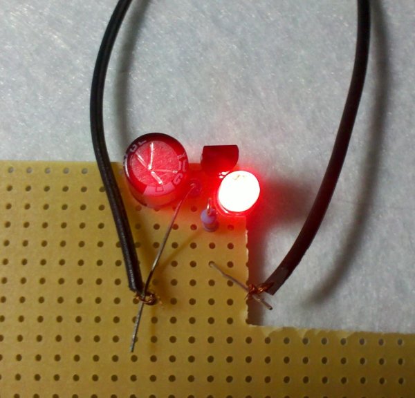
As can be imagined, this annoyed me. I decided to make a remote-control for the lamp. And since I was making a remote control, I decided that I might as well make it a dimmer – something I’ve wanted from this lamp for a while. I lacked any enclosures, so I used a tin can from what I can only assume were Chinese Altoids.
The IR protocol is very simple. At the physical layer I stole it from a previous project of mine. IR 940nm LED is used. The carrier frequency is 34KHz. A 1-bit is sent with 0.5 ms of modulated carrier and 1.5 ms of darkness. A 0-bit is sent with 0.5 ms of modulated carrier and 0.5 ms of darkness. The packet begins with a preamble byte of 0xFF. Then comes a header of 0x06. Then comes the device ID – a 32-bit identifier of the device. For this project, I used a device ID of {‘A’ ‘B’, ‘L’, ‘1’}. Then comes the button code.
2 bytes are used, big-endian. This project uses just three button codes: 0 for “power on/off”, 1 for “brightness up,” and 2 for “brightness down.” Then comes a checksum. It is used to make sure that the packet is received successfully and error-free. Then comes the trailer byte of 0xFF. This protocol allows for over 4 billion device types and more than 65 thousand buttons for each.
This month I am continuing with the PIC projects that I started in August. To be able to build this circuit you must build the August circuit which allows you the ability to program PIC’s.
The circuit this month is a simple 8 light chaser built around a PIC. This will demonstrate how easy it is to program a PIC and to utilize it in a circuit. The circuit works as follows. When power is supplied to the circuit the PIC resets and starts to process instructions that are programmed into it.
The program will turn on each LED in sequence with a small delay between each one. It will continue to do this until power is removed. The nice feature with this circuit is that you can program it to perform many complex lighting sequences. Normally you would have to rebuild a hardware based circuit to change the light sequence. With a PIC all you need to do is reprogram it and plug it back into the circuit. I am assuming that you will be using an IC socket. The circuit is show below and then I will discuss the program that is programmed into the PIC.
;File DEMO.ASM
;Assembly code for PIC16F84 micro controller
;Blinks LED’s on the outputs in a rotating pattern.
The program works as follows. The first few lines in the program are what is called comment lines. Comment lines assist us in documenting what each part of the programs function is. If a program is commented well, then it will be easier later own to understand why the program was written the way it was. Any line that begins with a semicolon is a comment line and will be ignored when the assembler is run. The assembler is another program that will convert these written instructions and convert them to binary data to be programmed into the PIC.

 to use with the Rapid cut & paste order form on their home page.