In our previous Nuvoton Microcontroller tutorials, we used a basic LED blinking program as a getting started guide and also interfaced GPIO as an input to connect a tactile switch. With that tutorial, we are fully aware of how to configure the Keil project and set up the environment for programming N76E003 Nuvoton microcontroller. It is time to use an internal peripheral of the microcontroller unit and move a little bit further by using the inbuilt Timer of the N76E003.
![Timers on Nuvoton N76E003 Microcontroller - Blink LED using Timer ISR and Timer Delay]()
In our previous tutorial, we only used a software delay to blink an LED, so in this tutorial, we will learn how to use the Timer delay function as well as the Timer ISR (Interrupt Service Routine) and blink two individual LEDs. You can also check out the Arduino Timer Tutorial and PIC Timer tutorial to check how to use timers with other microcontrollers. Without wasting much time let’s evaluate what kind of hardware setup we require.
Hardware Setup and Requirement
As the requirement of this project is to learn Timer ISR and the timer delay function, we will use two LEDs, out of which one will be blinked using timer delay in the while loop and another one will be blinked inside the ISR function.
Since an LED is available in the N76E003 development board, this project requires one additional LED and the current limiting resistor to limit the LED current. The components we require –
- Any color of the LED
- 100R resistor
Not to mention, other than the above components, we need N76E003 microcontroller based development board as well as the Nu-Link Programmer. Additionally, breadboard and hookup wires are also required for connecting all components.
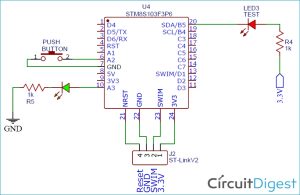
Circuit Diagram for LED Interfacing with Nuvoton N76E003
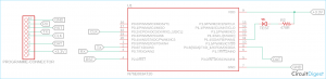
As we can see in the below schematic, the Test LED is available inside the development board and it is connected on port 1.4. An additional LED is connected to port 1.5. The resistor R3 is used to limit the LED current. On the extreme left, the programming interface connection is shown.
![Circuit Diagram for LED Interfacing with Nuvoton N76E003]()
Timer Pins on Nuvoton N76E003
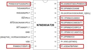
The pin diagram of N76E003 can be seen in the below image-
![Timer Pins on Nuvoton N76E003]()
As we can see, each pin has different specifications and each pin can be used for multiple purposes. However, pin 1.5 which is used as an LED output pin, it’ll lose the PWM and other functionality. But, that is not a problem as another functionality is not required for this project.
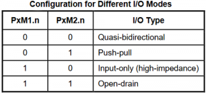
The reason behind choosing pin 1.5 as output and pin 1.6 as input is because of the nearest availability of GND and VDD pins for easy connection. However, in this microcontroller out of 20 pins, 18 pins can be used as a GPIO pin and any other GPIO pins can be used for output and Input related purposes, except pin 2.0 which is dedicatedly used for Reset input and it cannot be used as output. All GPIO pins can be configured in the below-described mode.
As per the datasheet, PxM1.n, and PxM2.n are two registers that are used to determine the control operation of the I/O port. Since we are using LED and we require the pin as general output pins, therefore we will use Quasi-bidirectional mode for the pins.
Timer Registers in Nuvoton N76E003
The timer is an important thing for any microcontroller unit. Microcontroller comes with an in-built timer peripheral. The nuvoton N76E003 also comes with 16-bit timer peripherals. However, each timer is used for different purposes, and before using any timer interface it is important to know about the timer.
Types of Times in Nuvoton N76E003
Timer 0 and 1:
These two timers timer0 and timer1 are identical with 8051 timers. These two timers can be used as a general timer or as counters. These two timers operate in four modes. In Mode 0, those timers will operate in 13-bit Timer/Counter mode. In Mode 1, the resolution bit of those two timers will be 16-bit. In Mode 2, timers are configured as an auto-reload mode with an 8-bit resolution. In Mode 3, the timer 1 is halted and timer 0 can be used as a counter and timer at the same time.
Out of these four modes, Mode 1 is used in most cases. These two timers can use the Fsys (System Frequency) in fixed or prescaled mode (Fys / 12). It can also be clocked from an external clock source.
Timer 2:
Timer 2 is also a 16-Bit timer that mainly used for waveform capture. It also uses the system clock and can be used in different applications by dividing the clock frequency using 8 different scales. It can also be used in compare mode or to generate PWM.
Same as like Timer 0 and Timer 1, Timer 2 can be used in auto-reload mode.
Timer 3:
Timer 3 is also used as a 16-bit timer and it is used for the baud rate clock source for the UART. It also has an auto-reload feature. It is important to use this timer only for Serial communication (UART) if the application requires UART communication. It is advisable not to use this timer for other purposes in such a case due to the conflicting process in the timer setup.
Watchdog Timer:
Watchdog Timer can be used as a standard 6-bit timer but it is not used for this purpose. The use of Watchdog timer as a general-purpose timer is applicable for low power consumption applications where the microcontroller stays mostly in idle mode.
Watchdog Timer, as the name suggests, always checks whether the microcontroller is working properly or not. In the case of a hanged or halted microcontroller, WDT (Watchdog Timer) reset the microcontroller automatically which ensures that the microcontroller runs in a continuous code flow without getting stuck, hanged or in halted situations.
Self Wake-Up Timer:
This is another timer peripheral that serves a dedicated timing process the same as a watchdog timer. This timer, wake-up the system periodically when the microcontroller is running in low power mode.
This timer peripheral can be used internally or using external peripherals to wake up the microcontroller from sleep mode. For this project, we will use Timer 1 and Timer 2.
Programming Nuvoton N76E003 Microcontroller for Timers
Setting the Pins as Output:
Let’s start with the output section first. We are using two LEDs, one is the onboard LED, named Test, and connected with the port P1.4 and an external LED connected with the pin P1.5.
Therefore, these two pins are configured as an output pin to connect those two LEDs by using the below code snippets.
#define Test_LED P14
#define LED1 P15
These two pins are set as Quasi-bidirectional pin in the setup function.
void setup (void){
                P14_Quasi_Mode;
                P15_Quasi_Mode;
                }
Setting the Timer Function:
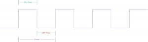
In the setup function, Timer 2 is needed to be configured to get the desired output. For this, we will set the T2MOD register with a 1/128 clock dividing factor and use it in an auto-reload delay mode. Here is the overview of T2MOD register-
The 4,5, and 6th-bit of the T2MOD register set the timer 2 clock divider and the 7th-bit set the auto-reload mode. This is done using the below line –
TIMER2_DIV_128;
TIMER2_Auto_Reload_Delay_Mode;
These two lines are defined in Function_define.h file as
#define                  TIMER2_DIV_128                               T2MOD|=0x50; T2MOD&=0xDF
#define TIMER2_Auto_Reload_Delay_Mode              T2CON&=~SET_BIT0; T2MOD|=SET_BIT7; T2MOD|=SET_BIT3
Now, these lines set the timing value required for the Timer 2 ISR.
RCMP2L = TIMER_DIV128_VALUE_100ms;
RCMP2H = TIMER_DIV128_VALUE_100ms>>8;
Which is further defined in Function_define.h file as-
TIMER_DIV128_VALUE_100ms 65536-12500 //12500*128/16000000 = 100 ms
So, 16000000 is the crystal frequency of 16 Mhz which is setting up the 100 ms time delay.
Below two lines will empty the Timer 2 Low and High bytes.
TL2 = 0;
TH2 = 0;
Finally below code will enable the timer 2 interrupt and start the Timer 2.
set_ET2;                                    // Enable Timer2 interrupt
set_EA;
set_TR2;                                    // Timer2 run
The complete setup function can be seen in the below codes-
void setup (void){
P14_Quasi_Mode;
P15_Quasi_Mode;
TIMER2_DIV_128;
TIMER2_Auto_Reload_Delay_Mode;
RCMP2L = TIMER_DIV128_VALUE_100ms;
RCMP2H = TIMER_DIV128_VALUE_100ms>>8;
TL2 = 0;
TH2 = 0;
set_ET2;                                    // Enable Timer2 interrupt
set_EA;
set_TR2;                                    // Timer2 run
}
Timer 2 ISR Function:
The Timer 2 ISR function can be seen in the below code.
void Timer2_ISR (void) interrupt 5
{
                  clr_TF2;                                             //Clear Timer2 Interrupt Flag
                  LED1 = ~LED1;                                                                                                                                                                                                                                  // LED1 toggle, connected in P1.5;
}
Clr_TF2 Will clear the Timer 2 interrupt flag and the LED will get toggled whenever the ISR Function is called. As the interrupt is set for 100 ms, the LED will blink in a 100 ms time intervals.
Main Function and while loop:
A Hardware, if connected with the power and working perfectly then it should give output continuously and the application never stops. It does the same thing for infinite times. Here comes the function while loop. The application inside the while loop runs infinitely. At first, the setup function is called.
Source: Timers on Nuvoton N76E003 Microcontroller – Blink LED using Timer ISR and Timer Delay
The post Timers on Nuvoton N76E003 Microcontroller – Blink LED using Timer ISR and Timer Delay appeared first on PIC Microcontroller.