the PIC12F629 on a microcontroller based electronic dice. electronic DICE with 14 LEDs dual membranes prepared for application software mikroc used to give random results when a button is pressed for 3 seconds if… Electronics Projects, Electronic Dice Circuit With PIC12F629 “microchip projects, microcontroller projects, “

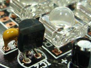
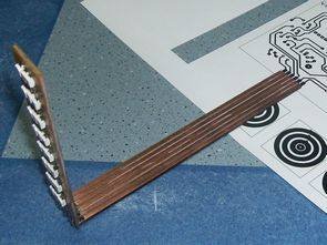
the PIC12F629 on a microcontroller based electronic dice. electronic DICE with 14 LEDs dual membranes prepared for application software mikroc used to give random results when a button is pressed for 3 seconds if not used within 15 seconds after it goes to sleep mode normal operation of the circuit of the button continues. Electronic DICE circuit PCB Sprint layout prepared with ISIS simulation software source code that belong to the file and drawing.
ELECTRONIC DICE CIRCUIT
ELECTRONIC DICE MICRO C SOFTWARE
#define Butt GPIO.F3
#define On 0 // button on - GP3=0

void main()
{
unsigned char LED1, LED2, i, Timer = 0, Time_off = 0;

TRISIO = 0;
GPIO = 0;
INTCON = (1<<GPIE); //
IOC=0b00001000; // enable int. on change GP3
T1CON = 1 ; // TMR1-on, 1/65535
CMCON = 7 ;

while(1)
{
if (PIR1.TMR1IF == 1)
{
PIR1.TMR1IF = 0;
Time_off++ ; // increment off-timer to 1 at each 65ms
}

if (Butt == On)
{
Time_off = 0; // clear off-timer
LED1 = (TMR1L%6)+1; //
LED2 = (TMR1H%6)+1; // rand. led1 and led2

for (i=0; i<150; i++) // indication 150*20ms = 3 sec.
{ GPIO = (1<<4)|LED1;
Delay_ms(10);
GPIO = (1<<5)|LED2; Delay_ms(10); } GPIO = 0; } else { if (Time_off > 250)
{ // to sleep in 15s
Time_off = 0;
INTCON.GPIF=0;
GPIO = 0;
asm sleep;
}
}
}
}
ELECTRONIC DICE SCHEMATIC

Source: ELECTRONIC DICE CIRCUIT WITH PIC12F629 alternative link: electronic-dice-with-pic12f629.rar


The post ELECTRONIC DICE CIRCUIT WITH PIC12F629 appeared first on PIC Microcontroller.