RGB REMOTE (pinguino+web+linksys)
This project has several uses, it is basically a way to control an RGB LED group (tricolor with common ground) via a web page to select which color we want to show.

It may be a way to harmonize a room, change the color of a swimming pool or just fooling aroun
Step 1
RGB REMOTE webserver and serial connection

In my case the web server is in Linksys router which I have “hacked / tunner” and installed a version of Linux opensource … in this case OpenWRT 9.02, with this special version for this type of equipment, It can be more flexible than the original software. Installing LUA and one webserver and I have all that I will need.
As to the little memory space of this team, to host my website, I have included a change and I have installed a 1GB SD card as hard drive so you can play and install things without fear to occupy the 5Mb which has by default. I’ve also created two output interfaces for internal serial ports by default has LINKSYS and that, in principle are control consoles, modifying a bit its used to connect any computer with RS232 communication.
Step 2
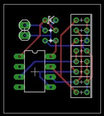
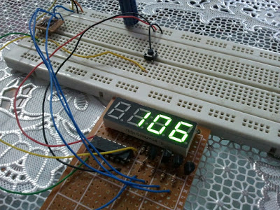
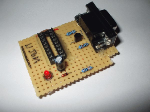
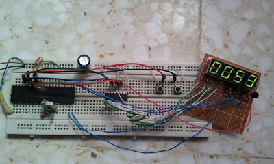
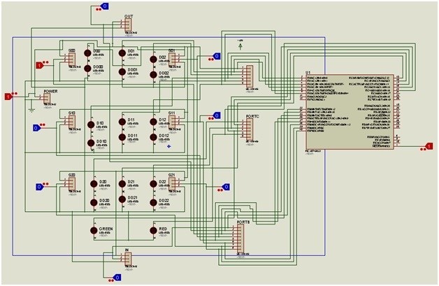
RGB REMOTE pinguino
I use a hardware interface with the 18F2550 microcontroller PINGUINO PIC Firmware v2, 12. This has a basic programming, which attempts to transfer via serial communication from the web server and has scripts that send orders and data via serial port. For example by sending the character “R” means to tell the microcontroller that the LEDs turn RED ONLY. And so with all the colors and combinations.
link original http://www.hackinglab.org/pinguino/index_pinguino.html
link Madrid http://pinguino.walii.es
The program basically tells the microcontroller that the serial port and listen when you get status R eg send a pulse to continuous 5volts particular output for the red LEDs. And finally sent to the serial port the color name that is kindled.
The code is as follows. USE PINGUINO GUI to programate it.
// Prueba de Puerto serie comandando RGB
// walii.es 2010
//aquí agregamos las posibles variables.
int i; //para nuestro contador de puertos
int key; //para la tecla que escucha por el Puerto serie.
void setup()
{
//Aquí configuramos los puertos de salida para que inicien
//en estado de SALIDA y APAGADOs.
for (i=1;i<4;i++){
pinMode(i,OUTPUT);
digitalWrite(i,LOW);
}
//Aquí configuramos el Puerto serie, para que escuche peticiones a 9600bps,
//suficiente para este proyecto.
Serial.begin(9600);
}
//Y por acá podemos ver la configuración de comandos a escuchar en el Puerto
//serie y hacer lo necesario para iniciar los leds que correspondan a la acción
void loop()
{
if Serial.available()
{
key=Serial.read(); //escucha el Puerto serie…
if (key==’r’) digitalWrite(1,1),digitalWrite(2,0),digitalWrite(3,0),Serial.print(“rojo”);
if (key==’v’) digitalWrite(1,0),digitalWrite(2,1),digitalWrite(3,0),Serial.print(“verde”);
if (key==’a’) digitalWrite(1,0),digitalWrite(2,0),digitalWrite(3,1),Serial.print(“azul”);
if (key==’m’) digitalWrite(1,1),digitalWrite(2,1),digitalWrite(3,0),Serial.print(“marron”);
if (key==’b’) digitalWrite(1,1),digitalWrite(2,0),digitalWrite(3,1),Serial.print(“morado”);
if (key==’n’) digitalWrite(1,0),digitalWrite(2,1),digitalWrite(3,1),Serial.print(“celeste”);
if (key==’w’) digitalWrite(1,1),digitalWrite(2,1),digitalWrite(3,1),Serial.print(“blanco”);
if (key==’c’) digitalWrite(1,0),digitalWrite(2,0),digitalWrite(3,0),Serial.print(“apagado”);
Serial.print(“\n\r”); //por ultimo imprimimos el nombre del color seleccionado.
}
//vuelve a comenzar el loop
}
For more detail: RGB REMOTE (pinguino+web+linksys) using PIC18F2550 microcontroller
The post RGB REMOTE (pinguino+web+linksys) using PIC18F2550 microcontroller appeared first on PIC Microcontroller.