Quantcast
Channel: LED Projects - PIC Microcontroller
Viewing all 387 articles
Browse latest View live

F1 Gantry Race Start Lights using PIC16F684

$
0
0

Description

Featured in Electronics Weekly Gadget Freak (15/08/2008)


The Control board for this project is now available in kit form or fully assembled and tested.
Please visit the Picprojects on-line shop for more details


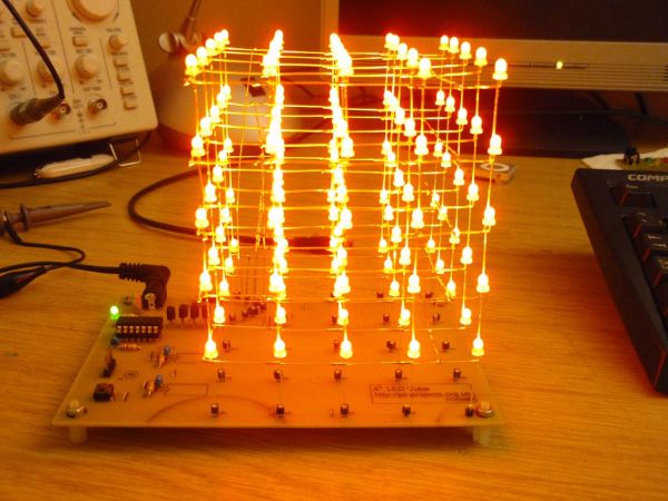
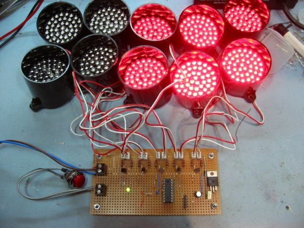
This project provides an simple F1 motor racing style 5 light race start sequence with a fixed or random delay that you can use on a real race track, kart circuit or even your slot-car circuit. 

Operation is simple; when the start button is pressed all the LED clusters are off. They then illuminate sequentially until all five LED clusters are on.  After a timed interval that can be either fixed or random depending on requirements the LEDs extinguish, signalling the start of the race.  Once the LEDs have extinguished simply press the start button again to initiate another race start sequence.

The latest version of firmware allows all the timings and the random delay to be customised to suit individual requirements.  We’ve also added an output that can be used to trigger timing software or operate a relay, sounder or other device when the start lights extinguish.

New from August 2012 is the ability to abort the start countdown sequence.  This feature has been requested by a number of people since the project was first published.

With the new ‘abort’ feature, pressing the start button again at anytime during the countdown will immediatly set the outputs to a fixed pattern indicating the start has been aborted.  This fixed pattern remains displayed until the start button is pressed and held for over 1 second at which point the controller resets ready for a new start.   The feature can be disabled at the time of purchase if it is not required.

Race Start Lights

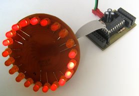
This page presents a complete application using 52mm (2″ inch) diameter LED clusters, but the software in the PIC microcontroller has been written to allow it to operate electro-mechanical relays, large arrays of LEDs, low voltage lamps, or even simply small 3/5/8 or 10mm LEDs.

Start sequence

When the start switch is pressed and released the first output turns on followed by the next four outputs. Default timings set the interval between each LED turning on  at 1 second but this can be customised.

After the fifth output has been on for 1 second, the controller starts a random delay that will last anywhere from 0 to 4 seconds at which point all outputs are turned off.  Again the duration of the random delay can be changed to suit requirements, or it can be set to a fixed period.

Once a start sequence has completed, simply press the start button again to initiate another start.

Timing and Modes

August 2012

Update: This kit is now shipping with Firmware V4 which supports an ‘abort start’ function.


The ‘abort start’ function is very simple to operate, using the same switch used to trigger the start countdown sequence.

After the switch has been released to trigger the start sequence it can be pressed again at any time during the countdown to abort the start.

If the start is aborted a fixed pattern is immediatley displayed on the light outputs.  This can only be cleared by holding the start switch down again for over 1 second resetting the controller ready for a new start.

If this feature isn’t required you can request to have it disabled when ordering a kit or programmed PIC.

Timing and mode options are held in the PICs EEPROM.  These values can be set when the PIC is programmed.  If you have access to a PICkit2 programmer the values can also be re-configured by the end user.  PICs supplied in the kit will have default timings set.  If you want customized timings you can provide us with a list of time values for each parameter shown in the timing data and we will pre-program them into the PIC supplied with the kit.

Modes and Timing and abort-function details

Display modes

The outputs can operate in either bar or dot mode.

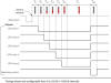
Timing DataThe timing diagram  shows all the parameters that can be configured.  These can be set from 0 to 25.5 seconds in 100mS intervalsDefault timings and mode supplied in the kit.

 0    ; light mode value, 00 bar, >00 dot
0    ; pre-light hold time value x 100mS [TP]
10   ; light 1 on time value x 100mS [TL1]
10   ; light 2 on time value x 100mS [TL2]
10   ; light 3 on time value x 100mS [TL3]
10   ; light 4 on time value x 100mS [TL4]
10   ; light 5 on time value x 100mS [TL5]
40   ; end hold delay value x 100mS (or maximum random time) [TH]
0    ; end mode value. 0 for random end delay, >00 for fixed end delay
5    ; start gate output time value x 100mS [TSTC]
41   ; b’00010101′  abort hold light state.
1    ; 0 – abort feature not enabled
; 1 – abort funtion enabled

This gives 5 lights illuminating in bar mode at 1 second intervals with a 0-4 second random delay at the end.  Start gate output is active for 0.5S

Abort function is enabled and displays ‘0-0-0’ pattern on light outputs

For step-by-step guide to editing and reprogramming the EEPROM timing data see here
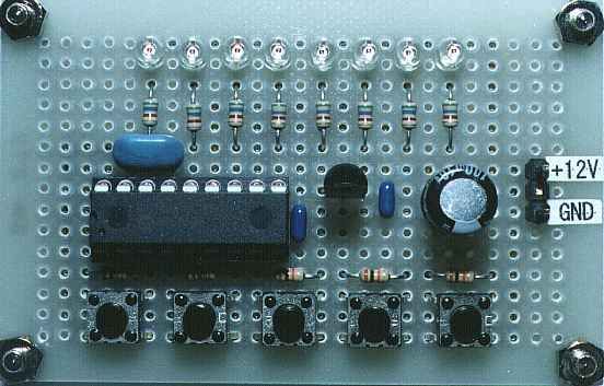

Circuit description

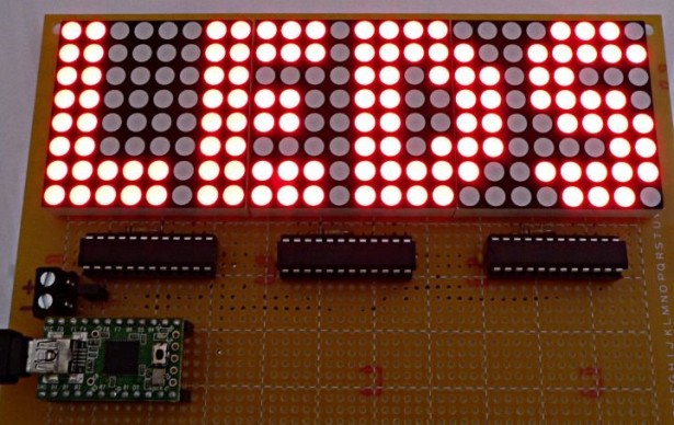
The circuit described on this page is designed around Kingbright’s 52mm LED cluster module which comprises 50 red LEDs in a waterproof housing with a brightness in excess of 16000mcd.  In the original version of this project each LED cluster was directly driven and all those LED’s required a hefty current with the ten LED cluster version requiring a power supply capable of delivering over 2amps at 12V DC.

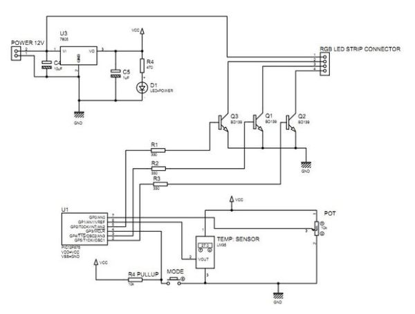
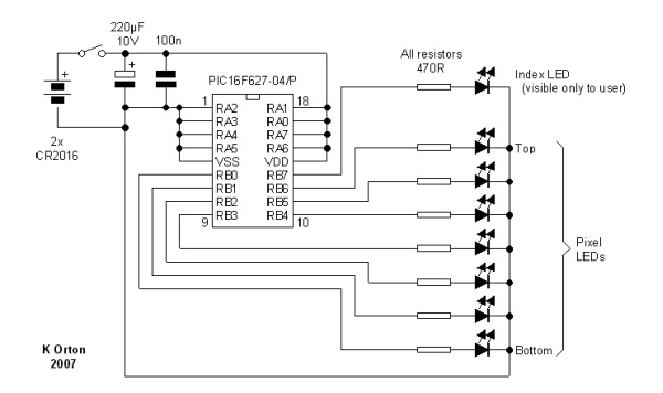
The input power to the board can be fed from either the DC Jack or 2-way screw terminal block.  These connectors are wired in parallel to give a choice of connection.  The positive supply is fed to the rest of the board via D1 which provides protection against a reversed power connection to the board.  D1 is a Schottky diode and is used in preference to a standard diode because of its a low forward voltage drop of around 0.25 volts.  A 78L05 voltage regulator provides the 5 volt supply for the PIC and a ULN2003A interfaces the PIC outputs to the LED modules.  LED1 is connected across the output of the 78L05 to provide a power-on indication.

For more detail: F1 Gantry Race Start Lights using PIC16F684

The post F1 Gantry Race Start Lights using PIC16F684 appeared first on PIC Microcontroller.


LEDactus using PIC18F1320 Microcontroller

$
0
0

The LEDactus is my version of a dry climate niche dweller like a cactus. LEDactus is immobile and attempts to survive by creating a pleasant display. This is of course in the hopes that passersby will be so entranced that they will build the LEDactus’ progeny.

LEDactus

Initial generations create a simple but pleasing display. Later generations attempt to produce more complex and mesmerizing displays. Finally, in the latest generations, a sense of touch is added to allow the LEDactus to interact with passersby.


The Circuit

In LEDactus I wanted to control a significant number of LEDs. Conventional wisdom says that it requires one I/O line to control one LED. Since the 18F1320 has only 16 I/O lines this could seriously cramp an inventor’s style. The figure below illustrates the standard approach to controlling an LED. In the first case a logic 1 on B0 turns the LED on, and a logic 0 turns it off. The second figure inverts the logic so that a logic 1 on B0 turns off the LED and a logic 0 turns it on. This schematic assumes that, like the 18F1320, the I/O pins are current limited to a value that won’t destroy the LED. If not, you’ll need to insert a series current limiting resistor.

Charlieplexing

Fortunately a clever fellow called Charlie Allen, an engineer at Maxim, thought of a way to control more LEDs with the same number of I/O lines. When an I/O line is configured as an output it sources or sinks current. Since microcontroller I/O lines can be reprogrammed to function as inputs, this adds a third state. This third state is like disconnecting the I/O port from the LED.

In practice, if you have N I/O pins to work with, you can control N x (N-1) LEDs. So a standard 8 bit port could control (8×7) 56 LEDs. With 16 I/O pins you could control (16×15) 240 LEDs.

The method controls LEDs in banks of N-1. Any LEDs in the active bank can be turned on independently. To turn on LEDs in another bank, the first bank is turned off. This means that LEDs are never full on. The fraction of time the LEDs are on, or duty cycle, is (1 / Number of Banks Used). Fortunately, an LED’s brightness does not drop linearly with the duty cycle. Even at 50% duty cycle (half on-half off) the LEDs retain nearly 80% of their perceived brightness.

LEDactus circuit

How Charlieplexing Works

The following diagram illustrates how charlieplexing works with 3 I/O ports.

In this example, I/O ports B0, B1 and B2 are used as bank select lines. We select a bank by setting one of these I/O lines as an output and setting it low (0).

If, for example, we set B0 to low, we use B1 and B2 to control LEDs 1 and 2. If we set either or both of B1 and B2 to high (1), the corresponding LEDs turn on. To turn off the LEDs we cannot however set B1 or B2 to low. This is the bank select condition and might cause LEDs in other banks to turn on as well. Instead, to turn off an LED in a bank we reprogram the controlling I/O line to be an input.


For more detail: LEDactus using PIC18F1320 Microcontroller

The post LEDactus using PIC18F1320 Microcontroller appeared first on PIC Microcontroller.

PIC Based Message wand

$
0
0

The project uses flashing LEDs to present shot message in the air by swinging a wand around above the head.

PIC Based Message wandA perfboard is used to construct the circuit that is powered by 2 coin cells type CR2016. The power fluctuations from excessive load on the coin cells can be prevented using the electrolytic capacitor. A toothbrush holder is used to make the message wand since swinging around the exposed sharp edges of circuit boards and batteries is dangerous.

The method of table look-up in a PIC is featured by the message wand program. Depending on the user requirements, the table that holds the message can be modified since it is in the form of pixel data. Synchronization is not used since the message is repeated at a fixed rate of about 3 times per second.

PIC Based Message wand SchematicThe mid-range PIC16F627 microcontroller is used by the message wand where one of its I/O lines is only capable of using a digital output and one is only capable of driving open drain. To ensure the internal oscillator of the PIC is running at about 4MHz, a register bit is implemented and addressed by wand.asm file.

For more detail: PIC Based Message wand

The post PIC Based Message wand appeared first on PIC Microcontroller.

LED flasher using PIC16C84 Microcontroller

$
0
0

This is my first simple PIC program. It will flash an LED continuously at approximately 1Hz. It is a very simple loop that delays for 500 milliseconds (half a second) with the LED on, and then delays for 500ms with the LED off. Thus, the LED flashes at 1 Hz!

PIC LED flasher
The schematic for this circuit shows that the wiring is simple: connect a crystal oscillator across pins 15 and 16 and add the capacitors to ground. Wire a 4k7 resistor to the MCLR reset pin 4 so the PIC will reset itself at startup. Then connect the LED via a resistor to pin 17.

When a 4 Mhz cryztal is used with PIC 16C84, the LED will flash at 1 Hz.

This program is available as:

title  "Flash - Flash an LED on an off at 1Hz"

; Mark Crosbie  8/22/98
;
;  The Program simply sets up Bit 0 of Port "A" to Output and then
;  loops, setting the value alternatively low and high
;
;  Hardware Notes:
;   Reset is tied through a 4.7K Resistor to Vcc and PWRT is Enabled
;   A 220 Ohm Resistor and LED is attached to PORTA.0 and Vcc
;

  LIST P=16C84, R=DEC
  errorlevel 0,-305
  INCLUDE "P16C84.inc"

;  Registers
Temp    equ     12              ;  16 Bit Dlay Variable

 __CONFIG _CP_OFF & _WDT_OFF & _XT_OSC & _PWRTE_ON

;  Mainline of Flash
  org 0
  clrf   PORTA                  ;  Clear all the Bits in Port "a"
  clrf   STATUS
  bsf    STATUS, RP0            ;  Goto Bank 1 to set Port Direction
  bcf    TRISA, 0               ;  Set RA0 to Output
  bcf    STATUS, RP0            ;  Go back to Bank 0

Loop
  movlw 1                       ;  Turn on the LED on Port A
  movwf PORTA                   ;

  call   Dlay                   ;  Delay Before Changing Values

  movlw 0                       ;  Turn off the LED on Port A
  movwf PORTA                   ;

  call   Dlay                   ;  Delay Before Changing Values

  goto Loop

;  Dlay Routine - Delay a Half Second before Returning

For more detail: LED flasher using PIC16C84 Microcontroller

Current Project / Post can also be found using:

  • microcontroller based led projects

The post LED flasher using PIC16C84 Microcontroller appeared first on PIC Microcontroller.

Remote controlled LED lighting effects

$
0
0

LED’s have become most important component in lighting industry due to its miniature size and less power consumption. Also LED lights are lot more attractive than the primitive lights used once. This project focused on building an remote controlled LED with multiple lighting effects. Imagine setting the mood of your room using remote, will be cool isn’t it.Remote controlled LED lighting effects

DESIGN OF RECEIVER AND CONTROLLER:

The receiver and Controller part comes with TSOP1738, a receiver capable of receiving IR beam of 38Khz which is the operating frequency of a normal household remote. This receiver acts as an activator for the controller connected to it. PIC12F1822, a 8 pin low end microcontroller is deployed as a controller in this project. Other low end microcontrollers can also be used for this purpose.Schematic Remote controlled LED lighting effects

The receiver and Controller part comes with TSOP1738, a receiver capable of receiving IR beam of 38Khz which is the operating frequency of a normal household remote. This receiver acts as an activator for the controller connected to it. PIC12F1822, a 8 pin low end microcontroller is deployed as a controller in this project. Other low end microcontrollers can also be used for this purpose.

The Microcontroller cannot produce enough current to drive a large set of transistors. So we are using a Transistors as a driver element in this circuit, RA2 pin from the controller feeds the signal to the base of these transistors. The reason for using two individual transistors is to create attractive effect when driven by a pulse from the Microcontroller. When the Pulse from MCU is Logic 1 Q1 will activate the LED’s connected to it, when it was logic 0 Q2 will activate all the LED’s connected to it.

For more detail: Remote controlled LED lighting effects

The post Remote controlled LED lighting effects appeared first on PIC Microcontroller.

24 Channel USB Connected LED Controller, upto 1A per Channel using PIC18F4550

$
0
0

24 Channel USB Connected LED Controller, upto 1A per Channel

This device is designed to be a versatile high-current LED controller, with the ability to sink or/and source currents up to 1A per channel with dissipation of up to 2.5w per channel. The various jumpers and transistor placement allow the device to control many different types of LED configurations with LED voltages of up to 36v.

Easily controls 5mm , 1w, 3w, 3w RGB, 5w RGB, 12v RGB LED lightstrip, 12v solid color light strip, common anode RGB LEDs, common cathode RGB LEDs. Any combination of LEDs in parallel/series. Whatever kind/wattage/configuration can be made to work, to a max of 1A per channel or 2.5w dissipation.

A PIC18F4550 controls 24 high-current darlington transistors. The PIC is ready for USB communication and using Microchip’s Library there is a multitude of USB connected devices can be made. From a simple emulated serial port, keyboard, mouse, HID, MIDI Devices, Audio Devices, and more. The available premium firmware allows the device to interact with the ColorMotion computer software, to create and upload patterns and settings to the device.

There are 4 pins left to use for other purposes, such as AdC, more transistors/mosfets, shift register whatever is needed. Accessed via the 6-pin polarized header, which can be used to connect to RA0, RA1, RA2, RA3, V+ and V-.ase. It accepts data from a PC/MAC/Linux over emulated serial port to the circuit board which outputs 8-bit PWM for all 24 outputs.
LED Controller
There are kits available in the Chromation Systems Store and all the files to recreate this project is in the ZIP file below.

Previous Version Assembly Instructions, Datasheet, Updates and More Info Can Be on the Main Website

The zip includes PCB diagram, Schematic Layout, and drill files. It is a single sided version of this circuit, so it is very DIY PCB friendly.

The 48 Channel Mono / 16 Channel RGB LED Controller, which is also USB connected, and is made for lower current LEDs is now available.


Supplies

Electronics: Purchase a Kit from The Store or Purchase a PIC or PCB separate.

  • 18F4550, DIP Buy One
  • Circuit Board, v.3  Buy One
  • 24x MPSW45AG Darlington Transistors or similar
  • USB Type-B jack, board mount
  • 20 mhz, version 3 can use any type, v1 & v2 require a series oscillator
  • 10kohm 1/4w resistor
  • 24x 1k ohm 1/6w resistor, value may vary depending on transistor
  • 220nF disc capacitor, VUSB
  • 2x 0.1uf disc capacitor
  • 2x 1uF electrolytic capacitor
  • 2x 22 pF disc capacitor
  • 5 pin ICSP header, optional
  • 6x 4-position screw down terminal blocks
  • 2-pin header, KK6410, use is optional
  • 2-pin housing, KK6471, use is optional
  • 6-pin header, KK6410, use is optional
  • 6-pin housing, KK6471, use is optional
  • 8 wire crimps for housings
  • 7805, 5v regulator, optional, can’t be used in most cases
  • Button assembly parts: Momentary Push button, perfboard, ribbon cable, and 10kohm resistor

Tools:

  • Soldering Iron
  • Diagonal Cutters
  • Wire Strippers
  • Flat screw driver for terminals
  • Multi meter

Other: Not included with the kit

  • USB Type A to Type B cable
  • LEDs or LED Strip, Find Some In The Store
  • Resistors for the LEDs

For controlling lower current LEDs over USB, please view 48 Channel Mono / 16 Channel RGB LED Controller

Resistors

Resistors:

  • Start with the transistor base resistors, R1-R4 are all 1k ohm(Brown – Black – Red)
  • R25 is a 10k ohm (Brown – Black – Orange) pull-up for MCLR
  • R26 and R27 are 22 ohm (Red – Red – Black) for the USB Data lines, these must be crossed on version 3 PCBs, one on the top side, and one on the bottom side of the PCB. See Images.

Select Jumpers

This board features jumpers to select if the transistors will be sinking or sourcing current. The board’s transistors are laid out with 16 on one side and 8 on the other. Each side can be set to sink or source voltage based on the SEL jumpers and the position of the transistors. SELx to NEGx for sink, SELx to POSx for source.

Set all transistors to sink:

  • SEL1 to NEG1
  • SEL2 to NEG2
  • SEL3 to NEG3
  • SEL4 to NEG4
  • SEL5 to NEG5
  • SEL6 to NEG6

Set all transistors source:

  • SEL1 to POS1
  • SEL2 to POS2
  • SEL3 to POS3
  • SEL4 to POS4
  • SEL5 to POS5
  • SEL6 to POS6

Set 16(Output1-16) to Sink and 8(Output 17-24) to Source

  • SEL1 to NEG1
  • SEL2 to POS2
  • SEL3 to POS3
  • SEL4 to POS4
  • SEL5 to NEG5
  • SEL6 to NEG6

See datasheet for more jumper selections.

*Note that each side has 3 selection points, so if it was needed, the main trace could be cut at any point and transistors on the same side could be mixed sink/source.

Oscillator, Disc Capacitors

Oscillator:

  • Oscillator, OSC position, goes in either way

Schematic LED Controller
Disc Capacitors:

  • C1 – 220nF, labeled 224M, goes in either way
  • C2 & C3 are installed later, leave them out for now.
  • C4 & C5 – 0.1uF, labeled 104, go in either way
  • C6 & C7 – 22 pF, labeled 224, goes in either way

Socket:

  • Line the notch on the end of the socket up with the notch in the top-side drawing.
  • Carefully line up the pins with the holes on one row of the socket then hinge it down into the adjacent row of holes.
  • Check to make sure all the pins are lined up, then press it in firmly.

For more detail: 24 Channel USB Connected LED Controller, upto 1A per Channel using PIC18F4550

The post 24 Channel USB Connected LED Controller, upto 1A per Channel using PIC18F4550 appeared first on PIC Microcontroller.

One-chip 11×10 LED matrix. using pic microcontroller

$
0
0

This project is pretty cool for a few reasons, and driving a huge LED matrix with a single 8-bit controller is just one of them. The idea was born when I bought 120 LEDs of the wrong type, and decided to do something with them. With that many LEDs, there are only a few things you can do, and a matrix is the natural first-place-winner in the competition of those ideas. One of the LEDs did not work, so a 12×10 matrix was out, so I settled for an 11×10 matrix. This meant I had to drive 110 LEDs. The only controller I had free was a PIC16F688 with 11 pins that can be used for output.After deciding not to use any other chips, charlieplexing was the way to go. The maximum number of LEDs one can charlieplex using N pins is N * (N – 1), so for 11 pins that number is 110. What a coincidence! 🙂

One-chip 11x10 LED matrix.The problem with charlieplexing is that for any two arbitrary LEDs, only one may be lit at a time. While it is true that some combinations of LEDs can be lit simultaneously. Not all are possible. Thus to use this matrix to show an image, one has to scan trough it rather quickly and turn each LED that needs to be on in succession. A slight nit: If one only scans through LEDs that need to be on, the more LEDs are lit, the dimmer they will be. This is annoying, so always scan through them all, but do not turn some on. This way timing is preserved and all lit LEDs always have the same duty cycle (1/110) regardless of how many of them are actually lit. How fast do you need to scan? Well, you’ll be relying on persistence-of-vision to make them appear solidly lit. For human eye to have this illusion, each LED needs to turn on at least 25 times a second. I chose about 30 times a second as a good value. This means that given the fact that we have 25 LEDs total, we need to switch which LED is on 30×110 = 3300 times a second. That’s a lot! I do not want to write my code with that constraint in mind, so interrupts are used. On PIC16F688 (8 MHz = 2 MIPS) this actually means that interrupts will be happening quite often. Timer0 is used with no prescaler (so it increments once per instruction), and only 32 instructions are allowed to go by between the end of one interrupt handler and the beginning of the next. So in technical terms: timer0 overflow interrupt updated which LED is on, and at the end reloads timer0 with 0xD0, causing it to overflow 0x20 instructions later. On PIC16F1823 this is simpler since it runs at 32MHz ( = 8 MIPS). Here timer0 uses a 1/8 prescaler and is reloaded with 0x60.


For more detail: One-chip 11×10 LED matrix.

The post One-chip 11×10 LED matrix. using pic microcontroller appeared first on PIC Microcontroller.

Multifunction RGB LED controller using PIC12F675

$
0
0

multifunction RGB  LED  controller  using low cost PIC12F675 microcontroller.

features:
1, 4+1 mode operation   a single potentiometer  and single button switch used for  multiple operation
2, EEPROM Memory option for mode selection :- the  last mode will be saved .

Multifunction RGB LED controller using PIC12F675
3, mode1  automatic hue saturation RGB LED light  color pattern – potentiometer  used for the vary the  color variation speed.
4, mode2 Manually select a color from hue saturation color chart using pot.
5, mode3 Temperature Indicator   blue color represent low temperature and  red color for highest temperature
6, mode4  White light   potentiometer used for vary  light brightness
7, mode5   OFF    potentiometer operation  is   disabled

Step 1: Circuit diagram

Step 2: Components list

components list

1,  PIC12F675 and 8 pin base
2,  BD139 – 3
3,1uf capacitor
4, 330E – 3
5, 470E 1a


For more detail: Multifunction RGB LED controller using PIC12F675

The post Multifunction RGB LED controller using PIC12F675 appeared first on PIC Microcontroller.


Arduino powered temperature sensing RGB LED nightlight using PICaxe

$
0
0

About a year ago I started on a project to make a temperature controlled nightlight. I was inspired by seeing these lovely LED lamps styled as mushrooms growing out of pieces of wood. Those mushrooms were made out of glass, which was somewhat beyond my skills. However I then saw some had used translucent sculpey to make mushroom nightlights on instructables. So with that discovery it seemed like it would be rather simple to do…

temperature sensing RGB LED nightlight

The first job was to solder up a three colour (RGB) LED (a super bright one from oomlout):

I then covered the LED in translucent Fimo:

As Fimo only needs to be heated to about 100C to set it’s ok to do this, as it won’t hurt the LED. Also LEDs don’t normally give out much heat, so covering them is ok. Of course this is a relatively low power (though quite bright) LED as well which helps.

I found a branch on the way home from work, which I cut up and sanded down. This formed the base for the mushroom:

As you can see I also opted for a chunky on/off button, in the style of the original mushroom lamps.

Next I put a small electronics project box into the bottom of the piece of wood and made space for a slide switch and power socket

At the time I decided to try to use a Picaxe 08m chip to control the LED and read from a temperature sensor. The Picaxe 08m has a native function to read the temperature from a DS18B20 One Wire digital temperature sensor. It also had just about enough inputs and outputs to handle controller the three colors of the LED and reading from a slide switch (to make it switch between temperature display and plain nightlight). The individual chips were also pretty cheap, so it seemed like a good plan at the time.

However the size of the circuit and number of components I needed to solder was all a bit too much for me:

temperature sensing RGB LED nightlight circuit

Eventually after much debugging I was able to get some things working – e.g. controlling the colour of the LED, but the temperature sensor just wouldn’t cooperate and always gave a high reading. I also managed to get through a few sensors due to mis-wiring them!

So I decided it was time to start again with the circuit. I bought a better soldering iron (a not too expensive digital temperature controlled one) and started on a new circuit:


For more detail: Arduino powered temperature sensing RGB LED nightlight using PICaxe

The post Arduino powered temperature sensing RGB LED nightlight using PICaxe appeared first on PIC Microcontroller.

Serial Addressable RGB PWM LED Driver using PIC16F628A

$
0
0

Overview

Ever since I made the serial controlled RGB LED PWM driver I’ve had many requests for an addressable driver.  Well I’ve finally got round to producing one.  The code is now completed and tested and the prototype boards are fully working.

The design process behind this project was to enable anyone with a bit of electronics knowledge to build an array of cheap RGB LED drivers that they can control from a PC without having to spend lots of money on expensive hardware, software etc. I specifically didn’t want to go down the DMX512 route as there are hundreds of commercially available products out there; if you need DMX512 you probably won’t be trying to build RGB controllers on the cheap (however, if you do check out this site for a DMX512 RGB LED).  The hardware for this project is designed around standard readily available parts and the serial interface uses a standard PC serial port and protocols.  You should be able to put together a single controller and get it hooked up to a PC for under £10 (assuming you have a PC)

I originally wrote the code to run on a 16F88 but subsequently converted it to run on a 16F690 as these are about 30% cheaper.  The ‘690 also has 2 extra I/O pins one of which has been used to enable the full version of the code to drive either common anode or common cathode 7-segment displays on the control panel.  I’ve  also taken the code for the free RGB PWM driver and ported it to the PIC 16F628A / 627A. Code and schematic can be found on this page.

The serial packet protocol is completely open so anyone can write their own software to control the drivers.  It is described in detail on its own page here.

RC Servo driver

During development I had an enquiry asking if the PWM output could control a servo.  I thought about this and came up with a three channel RC type servo driver that operates using the same serial control protocol. This makes it possible to put RGB Drivers and Servo drivers on the same serial bus and control them with a common command set.  Using the same algorithm that controls fading on the RGB driver, the three servos can be made to move at different speeds from one position to another autonomously.

I’ve deliberately kept the Microcontroller board separate from any LED driver electronics because the type of LEDs it could be used to drive, from low power 5mm LEDs to high power 3 watt star LEDs, are wide ranging and the potential applications enormous.  For the same reason, the control panel display on the full version is also optional and separated from the main MC board since it might be useful to some, while not to others.

While I primarily expect people to use a PC to send the control data to the drivers, there is a lot of potential for stand-alone controllers and interfaces using low-speed infrared or 433Mhz RF transceivers. In fact that’s one of the reasons for providing operation at bit rates down to 1200bps.

As time permits I’m am working on additional LED driver circuits and looking at PCB layouts as well as the PC software side of things and I’ll be making it available on this page.

If anyone can help out with PC software to share with other enthusiasts please contact me as I’m really struggling to find time to do all the work.

Update: Feburary 2008

I had intended to make two versions of the code available; a basic free version and a full feature version. I’ve given up on that so now the full feature version is available to download for free. 

For more detail: Serial Addressable RGB PWM LED Driver using PIC16F628A

The post Serial Addressable RGB PWM LED Driver using PIC16F628A appeared first on PIC Microcontroller.

POV Christmas Tree using PIC12F689 microcontroller

$
0
0

POV Christmas Tree

Still don’t have a tree for this holidays?, Don’t worry here you have a small, reusable, eye-catching tree for your holiday needs.

This project started as a SMD soldering tutorial for a course i’ve made in electronics, so it’s meant to be a one day project to learn a little bit of SMD soldering and also have the coolest of all trees.

Step 1

Gather the materials

For making the Awesome POV tree you will need:

1x    PIC12F689 or 1x PIC12F675 (PDIP8)
1x    8 pins IC socket
1x    LM7805 5V voltage regulator
1x    0.1uF capacitor 50V (1206 SMD)
1x    10uF capacitor 16V (1206 SMD)
10x  220R resistors 1/4W (1206 SMD)
9x    220R resistors 1/10W (0603 SMD)
1x   10K resistor 1/10W (0603 SMD)
18x  Green leds  (0805 SMD)
10x  Blue leds (0805 SMD)
1x    White led (0805 SMD)
1x    Pushbutton (5mm height)
1x    9V Battery clip
1x    9V Battery
1x   15x8cm PCB board
1x   12cm brushless fan (also works with 8cm ones)

IF you build the optional speed controller:
1x  LM317
1x  220R resistor (1206 SMD)
1x  5K 1 turn potentiometer
1x 12VDC power supply or some more batteries
4   meters of small cable for the DC power line

All components are easy to source from any electronics dealer, in my case I just have all the stuff around in my room.

You will need some tools:

– Soldering iron (15-25W) fine tip
– 0,5mm rosin core solder (or anything you have in hand)
– Small wire cutter
– Fine tip tweezers
– Cardboard knife
– Metallic ruler or metallic frame
– Double sided tape or epoxy glue
– Magnifying Glasses or standalone magnifying glass

Also you will need a way to etch the PCB design.

Sorry, that info isn’t the objective of this intructable, but follow this link for materials and method:
http://www.instructables.com/id/Sponge-Ferric-Chloride-Method-Etch-Circuit-Bo/step3/Etch-the-Board-Instant-Gratification/

Anyway my materials for etching are:
– Fine tip permanent marker pen
– Fine Steelwool
– Cheap magazine paper
– Ferric Chloride
– Small sponge
– Latex gloves
– Plastic Laminator (or iron)

And a way to program the microcontroller.
if you’re building a programmer try the cheap and dirty “Pablin 2” with the Winpic800 software.
link: http://www.pablin.com.ar/electron/circuito/mc/ppp2/index.htm

If you want an usb programmer, bouy pickit 2 from microchip or build/buy a pickit2 clone
link: http://sergiols.blogspot.com/search/label/PICKit2Clone
link: http://www.microchipdirect.com/ProductSearch.aspx?Keywords=PG164120

Step 2

Etch the board

POV Christmas Tree

Download the attached PCB file and print it so that the margins of the pcb are 15x8cm
Use “letter” for page size and you shouldn’t have any problems.

I’ll upload the schematic in a future update, but hey its christmas i’m supposed to be somewhere else helping for the meal.

There are a lot of different DIY techniques for etching at home, find the one that best suits you.

In my case I use the Toner Transfer on magazine paper with laminator / Ferric Chloride bath + sponge combo. (see images)

This is the cheaper / faster way to do it if you are making prototype PCBs more than 1 or 2 a month. For the occasional user try iron on transfer and sponge technique.

REMEMBER to use the darker mode on your printer and mirror the image for printing if you are using the transfer method.

(update 12/25/10: Fixed pullup and ground traces on the PCB please download 2.0 version)

Step 3

Cut and drill the holes

Cut the board in the pieces shown in the image.
Use a dremel disk or a filed back dent of a cardboard knife
The 5x2cm rectangular base is added in the final PCB drawing

Drill 1mm holes for the push button, the 5k pot and the wire bridges.
Also you can drill the TO220 regulators holes but is not necessary since we will surface mount them.

I use a “nail polisher” drill. No need for a fancy drill press or anything, the center hole on the etched copper pads will guide your drill bit straight down.

[Update 212/28/2010]: The attached file downloads as “.tmp”.  Just rename the extension to .rar to open it (sorry not my fault, maybe is the new instructables flash ulploader)

Step 4

Solder the pads, then the components

POV Christmas Tree 2

OK, now the SMD soldering tutorial part.For soldering SMD components FIRST always use some magnifying lens of some kind.
You WILL be able to see the process witouth it but it will really make your eyes strain. Not good if you love your eyes auto focus features in long term.

The logic behind soldering SMD is that you first solder just one pad of the component, place the component and align it with this pin and then solder the rest.
Easy, but the probability of missing a solder pad in the process is big so use this simple rules:

– Always solder from the same side in my case the right.
– Turn the PCB so that your top pads are to the right
– Presolder all the top pads
– Place and align all your vertical components with their top pads
– Turn the PCB 90º to the left
– Presolder all the right pads
– Place and align all the horizontal components with their right pads
– Turn the PCB 90º to the left again
– Solder the bottom pads of your components
– Turn the PCB 90º to the left again
– Solder the left pads of your components
-Solder the first pin of any major component and align the rest (chips, transistors voltage regulators, witches)
-Solder the rest of the pins of the major components
-Solder wire bridges from the bottom side

You’re done!

Always make sure with SMD to center the component to the pad.
Just look at the unsoldered pad when centering with the other one that it is in the middle of it.

One special note is with led polarity in SMD, usually they have a “T” mark on the bottom or dots on the top . The dots or the bottom part of the “T” indicates the cathode side “negative” (see the images for reference on the topic).
Cathodes are marked with a minus sign near the pad on the pcb

Another note is mounting though hole components like SMD. Just trim a little of the ic socket pins and solder from the side one corner pin first, align the rest and solder. For the TO220 regulators just bend the pins down, cut to size and solder, isolate the thermal pad from the board with some double sided tape.

Step 5: Program the chip

Download the hex file and program the chip with the following config fuses:

__config _CP_OFF & _CPD_OFF & _BODEN_OFF & _MCLRE_OFF & _WDT_ON & _PWRTE_ON & _INTRC_OSC_NOCLKOUT

That’s translated to:
h018C or
b110001100
on the config word

OK, 2.0 Firmware upgrade and fixed PCB uploaded, now it has 5 spinning modes and one stopped mode (default). Also fixed pushbutton ground and pullup trace (sorry small mistake on my part)

For more detail: POV Christmas Tree using PIC12F689 microcontroller

The post POV Christmas Tree using PIC12F689 microcontroller appeared first on PIC Microcontroller.

Complete Intro To PIC’s – Make an LED Flash Video

$
0
0

As the title suggests, this guide is targeted for those who are new to the world of PIC microcontrollers. I cover the basics from hardware to software along with programming the device and a few hints along the way.

I do assume a little bit of electronics knowledge – eg, reading circuit diagrams – I’m guessing if someone has the knowledge to Google “Intro To PIC’s” then they know something about basic electronics…

The post Complete Intro To PIC’s – Make an LED Flash Video appeared first on PIC Microcontroller.

5 LED CUBE Controller for PIC16F688

$
0
0

Circuit Description

The LED cube is made up from 125 LEDs arranged into 5 layers of 25 LEDs each.  The display itself is multiplexed so instead of requiring 125 connections it requires one to each of the five layers and 25 to each LED in a layer making a total of 30.  The cube is refreshed by a software interrupt routine with each layer active for 2ms, so the entire cube is refreshed every 10mS (100Hz). This results in a display with no visible flicker.

Only 8  I/O lines are needed to control the LED drivers for the cube which allows a tiny 14 pin PIC 16F688 microcontroller to control the whole cube. This micro has an internal 8Mhz clock and 4Kwords of program memory. 

Each of the LED layers is arranged in a 5 x 5 matrix and controlled by a transistor in an emitter follower configuration connected to the LED anodes.  When the respective layer control output from the PIC goes high the base of the transistor is held at +5V and the emitter sits approximately 0.7 volts below this.   The transistors used are BC637 NPN transistors, if an alternative is used it should be of similar specification, have an Ic rating of at least 1 amp and check the pin out.

The cathodes of the LEDs are connected to IC2 & IC3.  These are CAT4016 low voltage 16-bit constant current sink drivers.  The LED current is set by a single resistor connected to the RSET input of the IC (pin 23).  The 1K8 resistor (R1 & R2) set the LED current to ~33mA; this resistor can be altered to vary the current supplied to the LEDs.   (consult the datasheet CAT4016 before altering the value of this resistor)

orange 3mm LEDs

LED Cube kits after 10-March-2012 ship with the STP16DP05 driver IC.  This is functionally equivalent to the CAT4016 but requires 620R resistors for the current setting since it uses a different ratio in the current mirror circuit.  (Datasheet for STP16DP05)

Only change the resistor to reduce LED current, the circuit design shown may not work at higher LED currents and components may be damaged.

The advantage of using a constant current sink driver IC’s is that almost any LED can be used and the supply current remains constant regardless of the LED forward voltage.  If the output current does need to be altered, it only requires the two current setting resistor to be changed.

The outputs of the current sink drivers (IC2/IC3) are controlled by the LED data loaded into by the PIC microcontroller.  The driver ICs each contain 16 shift registers and an output latch. The PIC presents 1-bit of LED data to the serial input of IC2 (SIN).  The PIC then generates a pulse on the CLOCK input of both driver ICs to shift the data into them.  The two driver ICs are cascaded (SOUT of IC2 feeds SIN of IC3) so the PIC simply clocks in 25 bits of data.  Once all 25 data bits have been sent to the driver ICs the LATCH signal is pulsed to place the data on the current sink outputs.  The PIC then sets the respective layer drive transistor output high which turns on the required LEDs in one layer.

Signal Timing Detail for the LED Cube
made with a  Saleae USB 8 channel logic analyzer for mac, PC or linux

The three timing diagrams below are taken from an operating LED Cube using an 8-channel logic capture tool.  This information is provided to show the actual signals generated by the PIC microcontroller that control the LED cube.  Hopefully this clears up any ambiguity about how the hardware works.
(You don’t need to know about this to construct a working cube, it’s just for the techy ones out there)

Capacitors C1-C6 
The six capacitors C1 – C6 (3 x 100nF & 3 x 3.3uF)) provide power supply decoupling.  C4 and C5 in particular are important and should be tantalum bead (or low ESR electrolytic) types located close to the Vdd power pin of the two driver ICs.

Original design used 10uF capacitors for C4/C5/C6. The value of these capacitors has now be changed to 3.3uF

If you are building the LED Cube from the schematic place a 3.3uF and 100nF capacitor close to the Vdd power pin of each of the three IC’s in the circuit. You have then used all six capacitors shown on the schematic and placed them where they are needed.

JP1 & D1
The JP1 (ICSP header) allows in-circuit programming of the PIC microcontroller.  It will work with the genuine Microchip PICKit2 programmer and I’ve also tested with several clone versions of the PICkit2.  I don’t test with any other types of programmer.

Diode D1 allows the PIC programmer when attached to J1 (ICSP header) to detect power on the target board while preventing it from actually powering the target.  Depending on your particular programmer this diode may be omitted altogether, but if in doubt fit it.  If you don’t intend to program the PIC in-circuit you don’t need the diode.  This diode is not needed when using the Microchip PICkit2 programmer

For more detail: 5 LED CUBE Controller for PIC16F688

The post 5 LED CUBE Controller for PIC16F688 appeared first on PIC Microcontroller.

Dual 4-digit seven segment LED display with SPI interface using PIC12F

$
0
0

This project is an extension of my previous MAX7219 based SPI seven segment LED display module. The new display features eight 7-segment displays arranged in two rows of four digits. The on-board MAX7219 driver enables you to easily add eight 7-segment LED displays to your project using only 3 I/O pins of microcontroller. The major advantage of using this board is the time-division multiplexing operations required for continuous refreshing of the display digits are performed by the MAX7219 chip, thereby keeping the microcontroller free for doing other pressing tasks. It is suitable for displaying two variable values simultaneously in a project, such as displaying temperature and humidity, or current and voltage, etc.

8Digit SPI Display

Key Features:

  • based on MAX7219 display driver
  • SPI interface (3 pins)
  • operates at +5V supply
  • individual control of all digits and decimal points
  • display brightness control through software
  • dimensions 1.95″ x 1.95″ (50mm x 50mm)
  • two 0.36″ 4-digit seven segment LED display

The circuit diagram of this project is very simple (shown below) and derived from the datasheet of the MAX7219.

In the above board, digits from right to left in the first row are DIG0 through DIG3, whereas in the second row, the digits from right to left are DIG4-DIG7. The following example code is written in C and compiled with mikroC Pro for PIC compiler to illustrate how to interface this display module with the PIC12F project board. The program is for a dual 4-digit decimal counter. The first row of the display will be an up counter counting from 0000 to 9999 with one second duration. Meanwhile, the second row will count in reverse order from 9999 to 0000. The microcontroller used in the PIC12F board is PIC12F683. The details of MAX7219 registers and their initialization is described in my previous article Serial 4-digit seven segment display module.


For more detail: Dual 4-digit seven segment LED display with SPI interface using PIC12F

The post Dual 4-digit seven segment LED display with SPI interface using PIC12F appeared first on PIC Microcontroller.

PIC16F84A MemoSound Game

$
0
0

Game rules

You will have to memorize a melody, made of up to 62 steps.
A step is one of the four tones available in the game system.
In order to help you, each tone is associated to a color LED (yellow, green, orange, red) which lights each time the tone is played.PIC16F84A MemoSound Game
The game system plays the melody, then you have to repeat it correctly by pressing the button of the tone’s LED. At the beginning, the melody has only one step.
If you fail, an error melody is played, the melody is played again and you can try again to repeat it.
If you succeed, a new tone is added to the melody.
The longest melody is 62 step long, will you be able to learn it by heart ?

If you get bored with one melody, press the RB4 and RB5 buttons at the same time, the game system will create a new melody. If you want to modify the melody rythme, press the RB6 and RB7 buttons at the same time, and select a new rythme by pressing a key when the LED is on :
RA0 : very fast
RA1 : fast
RA2 : slow
RA3 : very slow (default)

Circuit Schematic

The game is battery operated, and the circuit is powered with a LP2950CZ-5.0 regulator with some decoupling capacitors. There is no main switch, because the circuit is in sleep mode when nothing happens. A standard 9V battery should work for weeks.

PIC16F84A MemoSound Game
Four switches are connected to the PORTB high nibble to allow wake-up on PORT change of the PIC when the player press a button. There is no pull-up resistors, because internal weak pull-up of the PIC is used.
The RB0 pin of the PIC drives directly a little piezzo speaker.
The PORTA low nibble drives fours LEDs, through current limitation resistors.
A cheap 8Mhz crystal is used to clock the PIC, you could add the two 15pf capacitors from crystal to ground to follow Microchip recommendation, but the PIC works very well without, just do it if you have a lazy PIC that does not start oscillator.

PIC C Source Code

This project is made for a PIC16F84A MCU, but could be changed to any other PIC MCU with only a very few adjustments.


For more detail:  PIC16F84A MemoSound Game

The post PIC16F84A MemoSound Game appeared first on PIC Microcontroller.


Chromation Systems RGB LED Tube Light

$
0
0

Built utilizing a 24 Channel High Current USB LED Controller to control 12 volt RGB LED Light Strip, in 8 separate groups. Each group has individual 8-bit PWM which can create over 16 million colors. And is driven at full current for maximum color saturation and accuracy. Using the ColorMotion Compatible Firmware, various colors patterns and effects can be created in the software and the uploaded to the device for it to run by itself, without a computer.
Chromation Systems RGB LED Tube Light
This device contains 8 groups of 2 segments(6 RGB LEDs) of 12v RGB LED Strip spaced out on a 2″ ID white PVC pipe, encircled in a 6″ diameter tube of white/cloudy plastic. Supported by two 6″ plywood discs. Its fairly simple and creates very eye catching effects. A favorite of everyone who sees it.

Electronic Kits including a 24 Channel High Current USB LED Controller Kit, 16 sections of 12v RGB LED StripDual-Voltage 12v & 5v PSU with Panel mount DC jack, and all the required Wire, is available for purchase. RGB LED Tube Light, 8 Channel , Electronics Kit

Or get a Full kit, with all the required electronics, the PVC Pipe, the Plastic Sheeting, the end caps all ready to use. RGB LED Tube Light, 8 Channel, Full Kit

Step 1: Supplies & Tools

Major Components in Project

Kits with all the electronic parts, including: 24 Channel High Current LED Controller Kit, 16 sections(3 RGB LEDs per) of 12v RGB LED strip, Dual-Voltage PSU with Panel mount DC jack, and Wire Can be Found in The Store

Or get a Full kit, with all the electronic parts listed above, the PVC pipe, the Plastic Sheeting, the end caps ready to use. Find it Here

Electronic Parts:

Power Supply: There are some options here, but you need at least 12v @ 1A and 5v @ 500ma

  1. Dual PSU with 12v @ 1A and 5v @ 500ma Power Supply(included with the full kit) Like This One
  2. 12v PSU @ 2A or more and a 5v step-down circuit or a DC/DC Converter

Hardware Parts:

  • 2″ ID PVC Pipe, white is best, got it from Home Depot, 10ft for ~$6, cut to 30.5″ if following exactly, otherwise measure!
  • 2x 1/2″ thick, 6″ Diameter Plywood disc endcaps
  • 32″ x 19.25″ x 50mil thick, HDPE Cloudy Plastic Sheet**
  • 1/8th Pope Rivets, I used white ones.
  • White Spray Paint
  • Aluminum Tape, or adhesive reflective film.

** This might be hard to find, I bought some 48″x24″ sheets through a wholesale distributor. I have no idea where else it could be found.
There are many things that could be utilized, such as semi-translucent paper(rice paper?) or some other type of plastic.

Tools:

  • Jigsaw or bandsaw
  • Sander or Sandpaper
  • Soldering Iron
  • Power Drill or Drill Press
  • Razor or Rotary cutter to cut the plastic sheeting.
  • Sizzors
  • Pop Rivet Gun and Rivets(I used white ones)

Step 2: Prepare the Pipe

Prepare the Pipe

Skeleton: A 2″ ID PVC pipe with an OD of about 2.35″ was used for support. Two segments of RGB Light strip can be cut so they butt together perfectly when wrapped on the outside of the tube. Two types of end caps are attached to the ends of the pipe that the plastic will be wrapped onto. The pipe’s length is less than the overall length so a space can be left for the controller and for the end caps. Allow 1″ for the controller, and one of the end caps will allow the pipe to recess into it, so it will be about 0.25″ deep. 32″ total light = 30.5″ pipe

  • Cut the pipe to length, try to get the cut end straight as possible, the pipe should be able to stand on one of the ends by itself.

Prepare the Pipe:

  • Find the flattest end of the pipe, that will be End Cap 2, the other end will be the controller end, mark it with a C or something.
  • Clean off the pipe with some soapy water, rubbing alchohol or other cleaner/degreaser
  • Mark the LED strip spacing with a sharpie, see the diagram for details
  • Cut 8 pieces of 8″ aluminum tape
  • Apply the tape on center to your spacing marksDrill a 1/4″ – 3/16″ hole in between the tape, 7 holes total

LED Strip:

  • Either Re mark the LED strip positions, or you will have to guess to place it.
  • Cut off 2 sections of RGB LED strip
  • Wrap it around, on the center of each piece of tape. Some brands can be cut and the ends will butt up to each other, but on other brands that are a bit to long, wrap the LED strip at a slight angle.
  • Apply all 8 sections of RGB LED Strip and press them down firmly.

Step 3: Wiring the LED Strip

Run Anode Wires: Each LED strip’s “+” or +12v lines need to be all connected in parallel(all share) and connected to the +12v input from the power supply jack.

  • Using some black or white wire(any color other than Red, Green or Blue) start connecting all the “+” positions on all 8 sections of LED strip together. Keep the wire tight, don’t let them have to much slack. Make sure the solder connections are good, shiny not dull.

RGB Line Wiring: Simple enough run wires from the RGB postions on the LED strips down to the end with the controller.

  • Starting from the hole in the pipe closest to the controller.
  • Feed down some 3 conductor RGB wire, until it comes out the end. Stiff wire can be pushed down, but other wire may need to be fed with a tool such as the bolt-grabber pictured, or some other method.
  • Have the wire hang out the end at least 4″, so there will be slack to connect them to the controller
  • From the hole where the wire was fed down from, pull the wire tight (so you still have 4″ out the end) and position it over to it’s LED strips solder pads, and cut all 3 strands.
  • Strip those ends and solder them to the LED strip
  • Label the wire channel 1 – 8
  • Repeat, running 8 sets of wires down the pipe to the controller.

Final Anode Wires: It is recommended to run 2 different anode wires to supply the +12v from the power supply jack.

  • From the top most hole, run a wire down to the controller end, leave 4″ or so and cut
  • Solder that wire to on of the LED strips anodes.
  • Repeat with another wire, but run it to on of the LED strips closer the controller

Step 4: End Caps

End Caps:

  • Layout and rough cut with a jigsaw, bandsaw or handsaw, two plywood discs 6″ in diameter
  • Finish the discs so they are as round as possible, use disc sanders, files and sand paper to do this
  • One disc gets a 2.36″(the OD of the pipe) diameter circle cut out of the middle using a 2.25″ hole saw, this is End Cap 1
  • The other is left as it is, End Cap 2
  • Paint both discs white, make sure to get the sides well. Painting the sides white will help hide them when the device is lit.

Finish the End Caps:

  • End Cap 2 Needs to get attached to the far end from the controller onto the pipe.
  • Either use a 2 1/4″ hole saw on some 5/8″ MDF to get a circle, and glue it on center to End Cap 2.
  • Or bolt a small block of wood inside the pipe so it sits flush to the end of the pipe, to have something to screw into from the end.

Make Faux Bottom: The fake bottom(end cap) is made out of 125mil polystyrene, but acrylic or hardboard could be substituted.

  • Cut out of 6″ diameter disc.
  • The plastic end cap and End Cap 1 need to have 3 holes drilled at the same time so they line up, these will be used to conceal the controller in the end compartment.
  • Place the plastic disc on top of End Cap 1, line them up
  • Mark 3 evenly spaced holes, 1/4″ in from the edge around the outer edge
  • Drill a 1/16″ or so hole through the faux bottom into End Cap 1(doesn’t need to go through)
  • Pick the best side and counter sink the holes on the faux bottom.

Attach End Caps:

  • End Cap 2(with the circle of MDF) goes on end farthest from the controller, seat it all the way down.
  • Drill 3 holes through the PVC pipe into MDF circle, and screw in with small coarse threaded screws.
  • Depending on the hole drilled through End Cap 1, you may need to apply some electrical tape to the pipe so that it will be snug when its attached. Loosely twist it as you wrap to make it thicker then wrap it once over normally.


For more detail: Chromation Systems RGB LED Tube Light

The post Chromation Systems RGB LED Tube Light appeared first on PIC Microcontroller.

Cooper Bills (csb88) and Anish Borkar (ab673)

$
0
0

Introduction

The Handy Lab Buddy is a tool every ECE should have. The four features of this tool include a talking voltmeter, logic probe, voltage averager, and frequency measurer. As a cheap and accurate device that outputs whatever being measured through speakers, it’s one of its kind and an essential tool for lab work.

Summary

Have you ever tried to debug a circuit and just wished your voltmeter would talk to you? Or have you ever been too lazy to turn on and calibrate the oscilloscope to measure the frequency? Well, this is the device for you. There are four operating modes of the Handy Lab Buddy. The first mode is a voltmeter that measures voltages up to 5V and says the voltage measured through speakers. The second mode is a logic probe that beeps once in a low tone if the output voltage is low and beeps twice in a higher tone if the output voltage is high. The third mode, a feature unique to this device, is a voltage averager that takes multiple samples in succession (perhaps a noisy voltage signal) and calculates the max, min, and mean voltage and speaks the values over a speaker. The fourth and final mode measures frequency with great accuracy from about 10 Hz to 100 kHz and speaks the value over a speaker. A device capable of all these functions and a “talking” ability at a very cheap cost is not available in the market today and is very useful to the ordinary engineer not wanting to invest in an oscilloscope. As very enthusiastic electrical engineers, we decided to build this device – simply for our own benefit, as it helps tremendously when debugging circuits.

We used quite a few features of the Atmel Mega644 MCU to implement this system, such as speech generation and output, multiple ADC conversions, the output of the pulse width modulator (PWM), and some others.Cooper Bills csb88 and Anish Borkar ab673

High Level Design

Rationale and Sources:

In all honesty, this was a secondary project idea for us, originally suggested by Bruce Land. Our original project idea, the Electronic Dartboard (discussed later), had tremendous problems with the hardware in the later weeks of the design cycle that forced us to abandon it. As our working efficiency and debugging experience increased dramatically in those frustrating few weeks, we managed to start and finish this new project within the final days of the semester.

Background Math:

The first big challenge for us was to get sound bites from AT&T and convert them for appropriate use for the MCU. Using the speech generation document by Bruce Land, we utilized his MATLAB programs to downsample from 16 kHz to 8 kHz and create header C files. The compression used in the MATLAB program was a differential pulse-code modulation (DPCM) with a 4:1 compression which sends 2:1 derivative samples.

To calculate the voltage generated, we had to use the built-in analog to digital converter in the MCU. Simple bit conversions were done, and we had to divide the 10-bit digital voltage output by 1024 over VREF (5V) to get a floating point value for the voltage. For the logic probe, the same thing was done, except an additional comparison was made to a threshold. The third feature, calculating the min, max, and average of samples of voltages, used pretty much the same principle as above except used additional variables to store the previous mean, min, max and sample number of samples. Frequency is measured using an elegant combination of software and hardware. Our frequency hardware first filters out the DC component of any input, then reapplies a DC bias, resulting in an AC waveform around the biasing point of our high frequency inverter. The output of this inverter is then stabilized. The final wave is thus a clean square wave, which is then used to trigger the external interrupt on the microcontroller. The software then responds to the interrupt, first synching the timers to the waveform, then measuring the the period of the waveform. Finally, the period is converted into frequency. Using this method, we can reliably measure frequencies from 10Hz to 100,000kHz.

There were two ISRs, one of them controlled the part of the speech played using a table, based on a timer, and the other, an external interrupt, controls triggers when to measure the time elapsed from the previous trigger, to measure frequency.

The user-interface of the Handy Lab Buddy is as demonstrated above. In the first two modes, after the analog voltage measurement is done, the signal needs to only go through an ADC before output to the LCD and to the speakers. For mode three, the voltage averager, the user presses the button on the probe when he/she is ready to take samples, then releases it to stop taking samples. The display shows the final output and it is automatically spoken. The fourth mode, frequency measurment, the user first has to change the banana plug connection to the frequency measurement pin (because of circuit isolation, described later in detail), then the signal passes through an inverter circuit to digitize the analog signal, which then triggers the external frequency ISR on the microcontroller (described later). After measurement in software, it is outputted onto the LCD and speakers. The four buttons that determine the modes are operated by a basic debounce state machine.

Hardware/Software Tradeoffs:

The biggest tradeoff during this design project was our decision to completely scrap our original idea and use this one. Our original idea was to create an Electronic Dartboard, where a player would draw concentric circles on a whiteboard, a infrared camera (removed form a WiiMote) would then be calibrated to the circles and display them on an LCD. Then, the user would “shoot” an IR dart (laser) at the whiteboard, which the WiiMote camera would have picked up and drawn the location on the LCD. However, the WiiMote IR camera was not reliable enough outside of it’s original controller. On top of that, we concluded the large LCD we were planning to use was fried after much testing. We worked on these getting these two hardware components to work by going to lab a lot of extra times overthree weeks to no avail. Thus, due to faulty hardware and being incredibly pressed for time, we decided to switch to this project, which our professor had initially suggested in class. In retrospect, we’re glad we made that decision, as we were able to come out with a complete, working product in a short span of time. The detailed schematics and code for the old project are described later.

One tradeoff we faced was during the design of our frequency measurer. We wondered how to calculate the frequency. One way of doing it was to use an Fast Fourier Transform algorithm as linked on the course website. However, we realized that the DFT/FFT would take up too much processing power and memory because of the look up tables. Besides, our frequency measurement only needs to measure the most prominent frequency, and the DFT/FFT would be doing unnecessary computation. Thus, we decided to take more of a hardware based approach, by digitizing the signal by passing it through an inverter, then using an interrupt to calculate the frequency.

Relationship to Standards:

There were no relevant IEEE, ISO, ANSI, or DIN standards related to this project.

Existing Patents, Copyrights, Trademarks:

There were no existing patents or trademarks associated with our project. We did utilize Bruce Land’s code for the implementation of the LCD and drivers, and his MATLAB code for converting .wav files from TextToSpeech to .h files.Cooper Bills csb88 and Anish Borkar ab673 schematic

Project Design

Hardware Design:

The hardware design for the Handy Lab Buddy was rather simple. To program the Atmel ATMega644 Microcontroller, the STK500 development board was used. The Mega644 MCU was then put on the Custom PC Board, provided by the lab. Soldering components onto the PC Board had to be done with careful precision, as the pins were small and very compactly laid out.

Our other significant pieces of hardware in this project were the 2-line LCD display in lab, the 4 buttons, a speaker, an inverter, and probes (with another button). The overall interfacing of the MCU with the rest of the hardware is shown below in the schematic.

Buttons

Buttons 1-4 were connected to port B7 to B4 (respectively) of the MCU. The top pin was grounded, while each of the other pins had a 10kΩ connected to Vcc. The resistor was needed there because when a button is pressed, the wire is shorted – to prevent this a resistor was placed there. These buttons operated on a debounce state machine, described later in the Software Design section.

Another button was used as an interface for the voice output . This was also connected to a 10kΩ resistor to Vcc, and to port B0. When this button was pressed, depending on what mode the system was in, the system would speak whatever was on the LCD screen.

Frequency, Inverter, and Protector Circuit:

If a signal was to be measured for it’s frequency, it needed to go through a circuit first to be processed. First of all, the diode/resistor connected to Vcc in the schematic was just to protect the MCU port A0 from being fried in case a voltage greater than 5V is fed into port A0. The signal picked up by the probe goes through a 0.4uF total capcitance array to filter out DC values, then gets DC shifted by the voltage divider, before going through the inverter to shift the center voltage of the signal. The purpose of the inverter is to output a square wave from any periodic signal given. There were a few ways of accomplishing this, one using an inverter or another using a Schmitt Trigger op amp circuit. We chose the inverter because there was no analog circuitry to worry about. Thus, the “analog” wave gets converted to a digital wave, as it converts every point on the wave below the 2.5V threshold to a logic 0 and above the threshold to a logic 1. The output of this input is then stabilized by two 22 pF capacitors. The final wave going into port D3 is a clean square wave used to trigger the external interrupt of the microcontroller.

Speakers:

The speakers are not shown in the schematic. They were simply connected via a headphone jack from port B3 (output of the PWM) to ground.

Liquid Crystal Display:

The LCD used in this project was simply the 16-pin LCD used in ECE 4760 Spring 2010 Lab 1. The pin assignments are as in the schematic.

Microcontroller Operation:

The Atmel ATMega644 microcontroller was the control module of the device. Port A0 was the ADC used to implement the first three modes. Port D3 was used to implement the frequency mode. Port B0 was the button on the probe, that made the speaker output a voice signal, which was coming from port B3. Ports C0-C2 and C4-C7 were used for the LCD. The diagram shows how the microcontroller was laid out on the custom PCB board. The photograph after the probes section shows the completed target board connected to the rest of the circuit. Two 1 uF capacitors were also used to connect Vcc and Gnd to remove any external noise in the circuit as a whole.

For more detail:  Cooper Bills (csb88) and Anish Borkar (ab673)

The post Cooper Bills (csb88) and Anish Borkar (ab673) appeared first on PIC Microcontroller.

How to take input with PIC18F4550 Microcontroller

$
0
0

Any microcontroller based system typically has an input and a corresponding output. Taking simple output with a PIC microcontroller has been explained in LED blinking with PIC18F4550. This article explains how to provide an input to the controller and get a corresponding output using PIC18F4550.

PIC18F4550 has a total of 35 I/O (input-output) pins which are distributed among 5 Ports. Each Port of a PIC microcontroller corresponds to three 8-bit registers (TRIS, PORT & LAT) which should be configured to use the Port for general I/O purpose. For more details, refer LED blinking using PIC.

 LED-Switch
To configure a particular port/pin as input, the corresponding TRIS register/TRIS bit should be set to high (1). For output, the relevant TRIS register/bit should be set to low (0).
For example, for PortD
·         To set the entire PortD as input
TRISD
Bit 7
Bit 6
Bit 5
Bit 4
Bit 3
Bit 2
Bit 1
Bit 0
Value
1
1
1
1
1
1
1
1
 
·         To set only 3rd pin (RD2) of PortD as input
TRISD
Bit 7
Bit 6
Bit 5
Bit 4
Bit 3
Bit 2
Bit 1
Bit 0
Value
1
 

·         To set  1st pin (RD0) as output and 4th pin (RD3) of PortD as input


For more detail: How to take input with PIC18F4550 Microcontroller

The post How to take input with PIC18F4550 Microcontroller appeared first on PIC Microcontroller.

Easy Way to Design an Automatic Driverless Train

$
0
0

Every one in the metro cities like Kolkata, Delhi enjoying the luxuries of the metro train ever spared a thought about the train? No, then let me give you a brief idea about the driverless automatic driven and controlled train. But before that let us have a brief recall about types of metro automation.

The Driver Controlled Mode:

In conventional modes, it’s the manual driver who drives the train and controls the train motion using the stationary light signals.

Easy Way to Design an Automatic Driverless Train

The Partially Automatic Mode:

In this mode, the driver drives the train while an external control system is used to constantly monitor the speed and acceleration of the train and provide required feedback to the driver.

Driverless Mode:

The whole operation and maintenance of the train is done automatically without any human intervention. The train stops and starts automatically and the doors are closed and opened automatically.

So, now let us fix our attention to the last mode i.e. The Driverless Mode

In a fully automatic driverless train, the control is done through a Communication based train control where a trackside computer is used to monitor the train running on the assigned line and convey this information to the centralized computer. The train is controlled by the automatic train control system.

Designing a Basic Prototype of a Automatic Driverless Train

The design will include the following components:

  • A rectangular body which holds all the other robotic components like the control circuit, the door etc.
  • A sliding door prototype
  • A couple of IR LED and photodiode arrangement
  • A control circuitry using a Microcontroller

Working of the Basic Prototype:

So let us see how our basic prototype works does:

  • The Automatic platform sensing and Door control system: It consists of an IR LED and a photodiode system. When the sensor senses the coming of the station, the motor driver automatically drives the motor such that the train comes to a halt and the door is opened when a person is sensed.
  • Passenger counter system: The train is also equipped with a passenger counter system which counts the number of passengers entering the train and when the count reaches a certain limit the door is closed automatically and the train will start moving after a certain time limit.

Easy Way to Design an Automatic Driverless Train Schematic

How to controls the Train Prototype:

  • Controlling the movement of the train: Normally when the train is moving, the IR LED-photodiode arrangement is placed such that both are placed parallel to each other and thus as the photodiode doesn’t gets the light pulses, it doesn’t conducts and as a result the microcontroller will get a high signal. Now as the train approaches a station, the IR light from the IR LED gets reflected by any object (suppose the station signal) and the reflected light falls on the photodiode, causing it to conduct and thus an interrupt low signal is given to the microcontroller through the transistor. The microcontroller is programmed so as to send signals to the motor driver to stop the motors. The operation of the motor is driven by the motor drive IC; here two stations are connected to the microcontroller through the motor drive.


For more detail: Easy Way to Design an Automatic Driverless Train

The post Easy Way to Design an Automatic Driverless Train appeared first on PIC Microcontroller.

Cheap PIC Programmer

$
0
0

This programmer works only with PIC16F84 but it’s great because it never causes errors and works with almost all computers,unlike some other homemade programmers.

Step 1: Step one : Materials

For this programmer you won’t need many materials.In fact , you will find all you need in your local electronics shop 😉

So here’s what materials you will need:
-IC Board
-RS232(Serial) FEMALE connector
-BC547B or 2N3904 (I couldn’t find the BC so i used 2N3904,it works great)
-5.1 V diode
-100 uF 16V Electrolytic Capacitor

Cheap PIC Programmer
-18 PIN IC Socket
-10Kohm resistor
-15Kohm resistor
OPTIONAL[
-Flashing red LED / 2.1 V Standard Red LED
-3.3Kohm Resistor]
-PIC16F84A Microcontroller
Tools:
-Soldering Iron
-Scissors or any other cuting tool

OPTIONAL[
-Hot glue gun]

Step 2: Step two : The scheme

This is the scheme you will use for your programmer.
As you can see , i tagged two connection in the scheme as “Optional point” one and two .
Those are the points where you will connect the “Optional” circuit i will show you in step 3

Step 3: Step three : The optional circuit

The optional circuit consists of the LED and 3.3 Kohm resistor marked as optional in step one.
One pin of the resistor goes in the Optional point one , the other pin goes in the anode(+) of the LED.
The cathone(-) pin of the LED will go in Optional point two.
If you don’t understand , use the ellipse marked area of the scheme below.

Cheap PIC Programmer Schematic

Step 4: Step four : Let’s build it !

Ok , you’ve got all you need.Now it’s time to build it.
DON’T CUT THE IC BOARD YET!
First solder the RS232 female connector in a corner of your IC Board.If you don’t know what are the connectors of the RS232 i uploaded an image.
After you soldered the RS232 , solder all elements according to the schematic,and then cut the board.
After you cut the board,secure all solderings with hot glue (optional).
You’re done!


For more detail: Cheap PIC Programmer

The post Cheap PIC Programmer appeared first on PIC Microcontroller.

Viewing all 387 articles
Browse latest View live


<script src="https://jsc.adskeeper.com/r/s/rssing.com.1596347.js" async> </script>