PIC18F4550 Programming Tutorial in Hardware C
PIC Tutorial, Mplab IDE – C18 compiler toolsuite
PIC18F4550, Looking the data sheet | Ports
PIC18F4550 Programming Blink led method 1
PIC18F4550 programming Method 2 Blink led
PIC18F4550 Blink LED 20MHZ Oscillator | XC8
Mplab X IDE and XC8 compiler Blink LED
PIC18F2550 programming: Blink LED | XC8
PIC18F4550 Tutorial: Blinking an LED | Chapter 3
Welcome to my third chapter of this programming tutorial for pic18f4550. From here we will start on programming with pic18f4550, my previous tutorials ( Tutorial 1 and Tutorial 2 ) must have given you some outlines regarding the tools that we need and how to setup the project in details to get started.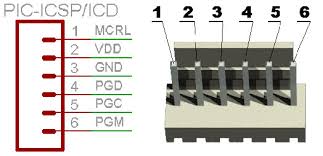
This is the first method of programming a pic18f4550. For the sake of example, we are going to take a simple case of blinking an LED, where we are going to blink two led’s on pin RB0 and RB1. In coming chapters we are going to see how to blink the same thing in different ways. Our primary target is to learn various methodologies of Programming same thing in different ways to develop a perfect coding habit.
PIC18F4550 Blink LED – Direct Approach
METHOD-1
First method is a direct and most common approach, where we are going to do all coding in one project file. MAIN.C. Here we are going to use Mplab ide and c18 compiler. It can be also done with Mplab X IDE , where there is no need of C18 compiler as the X8 compiler already includes all the necessary compiler files. However for this tutorial we will stick to Mplab IDE and C18.
Schematic
mentioned before we are going to blink two led’s on port B , RB0 and RB1. Here is a sample schematic. The code can be easily modified to blink other led as well.
The input voltage must never exceed 5 V or it might damage the microcontroller, you can also use a IC 7805 Voltage regulator or mcp 1702 to ensure the input is 5V.
The circuit can be easily built on a breadboard in no time.
Let’s Start with Coding
-Start MPLAB IDE and create a New Project as explained in the previous post for pic18f4550.
-Add a new file and save it as MAIN.C and save it in the project folder (Don’t forget to Check mark on “ADD to Project file”). You can use any name you wish..
– Now we have a blank empty project with a C file HOME.C
-Then start typing the source code as below.
Some of the sections in the code below are clickable to jump to the code explanation.
Source Code:
#include<p18f4550.h> // Include Header for PIC18f455
/* ******COMPILER DIRECTIVES FOR CHIP CONFIGURATION BITS *** */
#pragma config PLLDIV = 5 , CPUDIV = OSC1_PLL2 , USBDIV = 2 // You can write this way
// OR
#pragma config FOSC = INTOSCIO_EC
#pragma config FCMEN = OFF // OR this way
#pragma config BORV = 3
#pragma config WDT = OFF
#pragma config CPB = OFF
#pragma config CPD = OFF
/* *************** TIMER *************** */
void delayzz(void)
{ int i, j;
for(i=0;i<5000;i++)
{
for(j=0;j<2;j++)
{ /* Well its Just a Timer */ } } }
/* ****************** MAIN ****************** */
void main(void)
{
TRISB = 0 ; // PORT B Setting: Set all the pins in port B to Output.
while(1)
{
LATBbits.LATB0 = 1; // RB-1 to High
LATBbits.LATB1 = 1; // RB-1 to High
delayzz();
LATBbits.LATB0 = 0; // RB-0 to LOW
LATBbits.LATB1 = 0; // RB-0 to LOW
delayzz();
}
}
/* THE END */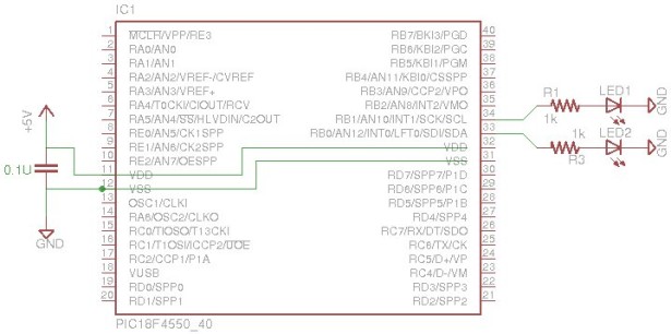
Download the code main.c or Download the entire Source code as Mplab Project.
Next step is to compile the code.
After the project is built the output files will be dumped into the same project folder, if a separate output folder is not defined for saving all the compiled files.
Now you can use your Programmer to burn the output .hex into the microcontroller.
Code Flow
-Define the header files for pic18f4550.
-Set the Microcontroller configuration settings with “compiler directives”.
-Define PORT settings:- The pins you want to use for blinking. Set the pin to output.
-Then set the timer:- For the time delay in-between the blinks.
-Define Pins to set as ON or OFF with a delay in-between.
-And finally make a loop where the main code will keep executing.
For more detail: PIC18F4550 Tutorial: Blinking an LED
The post PIC18F4550 Tutorial: Blinking an LED appeared first on PIC Microcontroller.