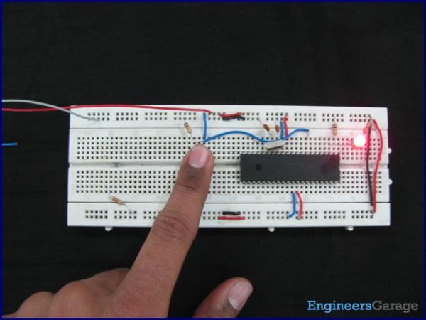
Any microcontroller based system typically has an input and a corresponding output. Taking simple output with a PIC microcontroller has been explained in LED blinking with PIC18F4550. This article explains how to provide an input to the controller and get a corresponding output using PIC18F4550.
PIC18F4550 has a total of 35 I/O (input-output) pins which are distributed among 5 Ports. Each Port of a PIC microcontroller corresponds to three 8-bit registers (TRIS, PORT & LAT) which should be configured to use the Port for general I/O purpose. For more details, refer LED blinking using PIC.
|
TRISD
|
Bit 7
|
Bit 6
|
Bit 5
|
Bit 4
|
Bit 3
|
Bit 2
|
Bit 1
|
Bit 0
|
|
Value
|
1
|
1
|
1
|
1
|
1
|
1
|
1
|
1
|

|
TRISD
|
Bit 7
|
Bit 6
|
Bit 5
|
Bit 4
|
Bit 3
|
Bit 2
|
Bit 1
|
Bit 0
|
|
Value
|
–
|
–
|
–
|
–
|
–
|
1
|
–
|
–
|

· To set 1st pin (RD0) as output and 4th pin (RD3) of PortD as input
For more detail: How to take input with PIC18F4550 Microcontroller
The post How to take input with PIC18F4550 Microcontroller appeared first on PIC Microcontroller.
