8×8 LED Array Multiplexed Infinity Mirror

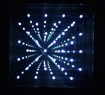
A little bit different than your regular Infinity Mirror. Using a piece of mirrored acrylic for the back mirror, 8 rows of 8 holes are drilled into in a grid pattern. A LED is then placed in each hole and wired up so that i can be multiplexed through a controller.
The frame I built for this project is very similar to my 8×8 Infinity Mirror, but instead of having glass for the rear mirror, I used mirrored acrylic which is easily drilled. And there are no LEDS around the outside. All the LEDs are in the back mirror and appear to be floating within it.
I got the idea after making an octagon mirror with a inner ring of LEDs, the effect of the LEDs floating in there is quite appealing, so I decided to do a small/simple project to demonstrate.
Building the actual frame will not be covered in detail here, but plans are in the ZIP. For detailed instructions on building the frame please see my other Instructable – 32 LED Infinity Mirror
The firmware is written in C18 for the PIC18F1320 and the TPIC6C596 high power shift register. Its a very basic program, with just 4 patterns to display, 2 switches change the pattern and the speed.
UPDATE: Kits are now available for this project, the LED controller is not being offered, but there are many different 8×8 array controllers out there to choose from. Quality glass 2-way mirror on the front and mirrored acrylic for the back, drilled and ready to use. Link
Check Out my Infinity Mirror Gallery
Step 1: Supplies
Get a Kit including the Frame Parts, front and back mirror, drilled and ready. LED Controller is not being offered.
Electronics:
– PIC18F1320
– 18pin socket
– TPIC6C596 shift register
– 16 pin socket
– x64 5mm LEDs, whatever color, I used white. Buy Some
– x3 10kohm 1/4w resistors
– x8 220 ohm resistors, may be different based on color
*Used high value resistors because they LEDs shouldn’t be to bright inside an infinity mirror or it won’t work as well.
– 1 uF capacitor
– 0.1uF capacitor
– x2 momentary pushbuttons
– 5v @ ~1A power supply with DC Jack Get One
Circuit Board:
– Solid strand wire
– Perfboard
Frame:
– Plans are on the next page or in my 32 LED Infinity Mirror
– I use 100mil Polystyrene, but acrylic or 1/8th masonite would work as well
Tools:
– Soldering Iron
– Hotglue gun
– drill and bits, for button hole
– 5mm drill bit for LEDs
– Utility Knife
I could put a kit together for everything or just certain parts, Contact Me to find out
Step 2
Build the Frame
The plans in the image below is for the 32 LED mirror. Rest are for this projects mirror frame.
Find where you will want the DC Jack and switches, I always choose a corner. Later the 2 switches will be soldered on some perfboard to be mounted in the holes. Take a look at your switches and find their spacing. With some masking or painters tape put some tape in the area of the holes and mark your layout on the tape.
Drill the holes for the 2 switches, I used a 5/16″ bit to drill them out then a utility knife to cut them more square. They will later get a black decal over them to hide the switches nearly completely.
Step 3
Drill the Rear Mirror

*Leave the protective film on the acrylic until later.
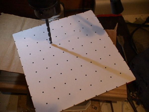
– Printout the drill pattern.
– Align it and tape it to the back of acrylic mirror.
– Place it on some wood or work surface that you can drill into that supports the acrylic. Ensure there is no particles that could scratch the face of the mirror.
– Using a 5mm drill bit or the closest standard one they sell, I found close enough to 5mm at Home Depot.
– A drill press works best, but otherwise go very slow and steady drill out all the holes.
Step 4
Place all the LEDs
Its now time to place all the LEDs into the acrylic from behind.
An 8×8 LED grid is controlled with Multiplexing which basically is to have all the LEDs cathodes(negative) all be bent over to the next one above it, so that a column of 8 LEDs will all have their cathodes in parallel, and be bent in way that the anode can be bent to the side and connect with the next LED in its row. So by sinking(allow path to ground) a column and sourcing(apply voltage) a row, a single LED can be controlled. Check the Internet for more detailed explanations.
This Instructable has good matrix directions.
– Check the images below and bend some LEDs, as shown
– You have to start from one side and work your way over like in the images. Or its hard to get at the solder points.
– As you work check to make sure the LEDs are bent suitably so they don’t touch anywhere.
Normally diffused LEDs are preferred in Infinity Mirrors, but if using clear lens ones like I am, because thats what I had on hand, before removing the protective film on the acrylic I sprayed my LEDs with a Frosted Glass spray paint to diffuse the light.
For more detail: 8×8 LED Array Multiplexed Infinity Mirror using PIC18F1320 microcontroller
The post 8×8 LED Array Multiplexed Infinity Mirror using PIC18F1320 microcontroller appeared first on PIC Microcontroller.